EP0865571B1 - Adsorptions-filter einer kraftstofftank-entlüftungsanlage eines verbrennungsmotors und verfahren zum betreiben dieser anlage - Google Patents
Adsorptions-filter einer kraftstofftank-entlüftungsanlage eines verbrennungsmotors und verfahren zum betreiben dieser anlage Download PDFInfo
- Publication number
- EP0865571B1 EP0865571B1 EP97926982A EP97926982A EP0865571B1 EP 0865571 B1 EP0865571 B1 EP 0865571B1 EP 97926982 A EP97926982 A EP 97926982A EP 97926982 A EP97926982 A EP 97926982A EP 0865571 B1 EP0865571 B1 EP 0865571B1
- Authority
- EP
- European Patent Office
- Prior art keywords
- housing
- adsorption filter
- adsorption
- filter
- fuel tank
- Prior art date
- Legal status (The legal status is an assumption and is not a legal conclusion. Google has not performed a legal analysis and makes no representation as to the accuracy of the status listed.)
- Expired - Lifetime
Links
- 238000001179 sorption measurement Methods 0.000 title claims description 30
- 238000002485 combustion reaction Methods 0.000 title claims description 13
- 239000002828 fuel tank Substances 0.000 title claims description 13
- 238000000034 method Methods 0.000 title claims description 5
- 238000013022 venting Methods 0.000 title claims 4
- 230000008929 regeneration Effects 0.000 claims description 4
- 238000011069 regeneration method Methods 0.000 claims description 4
- 239000000463 material Substances 0.000 claims description 3
- 230000001105 regulatory effect Effects 0.000 claims description 2
- 230000000694 effects Effects 0.000 claims 1
- OKTJSMMVPCPJKN-UHFFFAOYSA-N Carbon Chemical compound [C] OKTJSMMVPCPJKN-UHFFFAOYSA-N 0.000 description 10
- 238000009423 ventilation Methods 0.000 description 9
- 239000000446 fuel Substances 0.000 description 6
- 238000005192 partition Methods 0.000 description 3
- 239000003463 adsorbent Substances 0.000 description 2
- 238000011001 backwashing Methods 0.000 description 1
- 230000010354 integration Effects 0.000 description 1
- 238000004519 manufacturing process Methods 0.000 description 1
- 230000007704 transition Effects 0.000 description 1
Images
Classifications
-
- F—MECHANICAL ENGINEERING; LIGHTING; HEATING; WEAPONS; BLASTING
- F02—COMBUSTION ENGINES; HOT-GAS OR COMBUSTION-PRODUCT ENGINE PLANTS
- F02M—SUPPLYING COMBUSTION ENGINES IN GENERAL WITH COMBUSTIBLE MIXTURES OR CONSTITUENTS THEREOF
- F02M25/00—Engine-pertinent apparatus for adding non-fuel substances or small quantities of secondary fuel to combustion-air, main fuel or fuel-air mixture
- F02M25/08—Engine-pertinent apparatus for adding non-fuel substances or small quantities of secondary fuel to combustion-air, main fuel or fuel-air mixture adding fuel vapours drawn from engine fuel reservoir
- F02M25/0809—Judging failure of purge control system
- F02M25/0818—Judging failure of purge control system having means for pressurising the evaporative emission space
-
- F—MECHANICAL ENGINEERING; LIGHTING; HEATING; WEAPONS; BLASTING
- F02—COMBUSTION ENGINES; HOT-GAS OR COMBUSTION-PRODUCT ENGINE PLANTS
- F02M—SUPPLYING COMBUSTION ENGINES IN GENERAL WITH COMBUSTIBLE MIXTURES OR CONSTITUENTS THEREOF
- F02M25/00—Engine-pertinent apparatus for adding non-fuel substances or small quantities of secondary fuel to combustion-air, main fuel or fuel-air mixture
- F02M25/08—Engine-pertinent apparatus for adding non-fuel substances or small quantities of secondary fuel to combustion-air, main fuel or fuel-air mixture adding fuel vapours drawn from engine fuel reservoir
- F02M25/0854—Details of the absorption canister
Definitions
- the invention relates to an adsorption filter of a fuel tank ventilation system an internal combustion engine the preamble of claim 1 and a method to operate this system.
- the filter as such is off, for example DE 41 24 465 A1 known.
- the invention is concerned with of building such a filter with the problem, the individual Aggregates of the fuel tank ventilation system as compact, efficient to manufacture and easy to attach to the tank as well as the intake air line of the internal combustion engine To design module part.
- the teaching of claim 6 ensures that by in the intake line of the internal combustion engine, through which Adsorption filter-led air the engine combustion process not negatively affected.
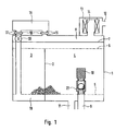
- an adsorption filter housing 1 In an adsorption filter housing 1 are through a partition 2 a larger and a smaller chamber for receiving of activated carbon as an adsorbent for fuel vapors a tank, not shown, of an internal combustion engine educated.
- the smaller chamber is 3 and the larger one Chamber labeled 4.
- the two chambers 3 and 4 are vertically above and below with permeable covers 5 and 6 closed, being on the covered by the activated carbon opposite sides of the covers 5 and 6 each for training a flow channel a distance from one adjacent wall of the filter housing 1 is given. Perpendicular below is this flow space between the smaller and the larger chamber 3 or 4 separated by the partition 2.
- the flow channel lying vertically above the upper cover 6 is from an intermediate wall 7 of the filter housing 1 educated.
- the partition 7 is together with an area the outer wall of the filter housing 1 also an additional one separate flow channel 8 is formed.
- connection piece 9 For the connection of a tank ventilation line is in the Larger chamber 4 leading connecting piece 9 is provided. Via the mouth of this connection piece leading into the activated carbon 9, a sieve basket 10 is put over.
- Another one Connection piece 11 is the larger chamber 4 with a Engine operation under vacuum area of the intake air line of the internal combustion engine connectable. The last one said connection can be interrupted by a valve.
- a connecting piece 12 leading to the atmosphere is located connected to one with the adsorption filter housing 1 Air filter housing 13. Sits in the air filter housing 13 an annular air filter 14, the radially outer one Area with the connecting line 12 to the atmosphere and its radially inner area with the flow channel 8 is connected.
- a housing is directly connected to the filter housing 1 a compressed air source 15, this compressed air source specifically is an air pump.
- the connection of the housing of the Compressed air source 15 is in the interior of the filter housing 1 leading connecting lines 16 and 17 given. Within these connecting lines are each the housing of the Compressed air source 15 from the filter housing 1 vibration-decoupling Intermediate elements 18.
- the connecting line 17 leads from the pressure side of the compressed air source 15 out into a flow space 19 which is connected to that of the larger one Chamber 4 downstream end of the smaller chamber 3 adjacent.
- a shutoff valve 20 provided, in particular at the transition from Housing of the compressed air source 15 is arranged to this line can be.
- the compressed air source is located via the connecting line 16 15 on the suction side with the flow channel 8 in connection.
- Fuel vapor flowing out of a tank, not shown passes through the connecting line 9 in the with activated carbon filled larger chamber 4 of the adsorption filter housing 1.
- the chamber 4 leaves the one pre-treated there Fuel vapor in the direction of the smaller one too Activated carbon filled chamber 3, which he in the flow space 19 flows through.
- From there the fuel passes freed tank ventilation flow via the supply and discharge lines 17 and 16 the compressed air source 15 to through the Flow space 8 through the air filter 14 through the Connection piece 12 to get into the atmosphere.
- the compressed air source 15 is for this flow guidance of the tank ventilation flow permeable design.
- the tank ventilation system can carry out leakage safety checks overall by the compressed air source 15 below Pressure.
- the area to be pressurized lies between the connecting piece 11 and the connecting line 17 who did not conduct the test shown valves are closable and includes the the connecting piece 9 connected not shown Fuel tank.
- the compressed air is directly inside the housing the compressed air source designed as a compressed air pump 15 generated and introduced via line 17 into the system.
- the compressed air source 15 sucks the one to be compressed Air via the connecting line 16 from the air filter housing 13 on.
- the exact type of leak test the tank ventilation system is known per se and therefore needs it no further explanation here.
- a one-way valve 21 with locking action be arranged in the direction of the fuel tank.
- the air flow that is generated by the Air pump 15 is conveyed through the filter 1, depending on the relevant engine operating data, the Exhaust gas composition and / or the fuel load state of the adsorption material of the filter 1 controlled or regulated.
Landscapes
- Engineering & Computer Science (AREA)
- Chemical & Material Sciences (AREA)
- Combustion & Propulsion (AREA)
- Mechanical Engineering (AREA)
- General Engineering & Computer Science (AREA)
- Cooling, Air Intake And Gas Exhaust, And Fuel Tank Arrangements In Propulsion Units (AREA)
- Supplying Secondary Fuel Or The Like To Fuel, Air Or Fuel-Air Mixtures (AREA)
- Separation Of Gases By Adsorption (AREA)
Description
Claims (6)
- Adsorptions-Filter einer Kraftstofftank-Entlüftungsanlage eines Verbrennungsmotors mit Anschlüssengekennzeichnet durch die Merkmale,gegenüber der Atmosphäre,zu dem Kraftstofftank,zu der Ansaugluftleitung des Verbrennungsmotors,
von denen diejenigen gegenüber Atmosphäre und zu der Ansaugleitung durch jeweils ein Ventil verschließbar sind,sowie zu einer Druckluftquelle, mit der die Entlüftungsanlage bei geschlossenen Zu- und Abführventilen für regelmäßig vorzunehmende Dichtheitsprüfungen unter Druck gesetzt werden kann,das Adsorptions-Mittel ist in zwei voneinander getrennten strömungsmäßig in Reihe geschalteten volumenverschiedenen Adsorptions-Kammern des Filters gelagert,die größere (4) der beiden Adsorptions-Kammern (3, 4) ist mit den Anschlüssen (9, 11) zu einerseits dem Kraftstofftank und andererseits der Ansaugluftleitung versehen, wobei die Öffnung des Anschlußstutzens (11) der Ansaugluftleitung auf das strömungsmäßig von der kleineren Kammer (3) entfernt liegende Ende der größeren Kammer (4) mündet,die Druckluftquelle (15) ist in einem Gehäuse untergebracht, das an dem Gehäuse (1) des Adsorptions-Filters angebracht und über eine erste Leitung (17) mit dem strömungsmäßig von der größeren Kammer (4) entfernt liegenden Ende der kleineren Kammer (3) und über eine zweite Leitung (16) über ein an dem Gehäuse (1) des Adsorptions-Filters vorgesehenes Luftfiltergehäuse (13) mit der Atmosphäre verbunden ist,das Gehäuse der Druckluftquelle (15) liegt in dem Strömungsweg zwischen der Atmosphäre und dem strömungsmäßig von der größeren Kammer (4) entfernt liegenden Ende der kleinen Kammer (3). - Adsorptions-Filter nach Anspruch 1,
dadurch gekennzeichnet,
daß die Strömungskanäle (16, 8; 17, 19) zwischen dem Gehäuse der Druckluftquelle (15) und der Atmosphäre einerseits und der kleinen Kammer (3) andererseits innerhalb des Gehäuses (1) des Adsorptions-Filters verlaufen. - Adsorptions-Filter nach Anspruch 1 oder 2,
dadurch gekennzeichnet,
daß das Gehäuse der Druckluftquelle (15) über Anschlußleitungen (16, 17) schwingungsentkoppelt mit dem Gehäuse (1) des Adsorptions-Filters verbunden ist. - Vorrichtung nach einem der vorhergehenden Ansprüche,
dadurch gekennzeichnet,
daß in der Verbindungsleitung zwischen dem Adsorptions-Filter (1) und dem Kraftstofftank ein in Richtung des Kraftstofftankes sperrendes Einwegeventil (21) angeordnet ist. - Verfahren zum Betreiben einer Kraftstofftank-Entlüftungsanlage eines Verbrennungsmotors mit einem Adsorptions-Filter nach einem der vorhergehenden Ansprüche,
dadurch gekennzeichnet,
daß die Druckluftquelle (15) während des Motorbetriebes zumindest teil- und zeitweise Luft in die Ansaugluftleitung des Verbrennungsmotors fördert. - Verfahren nach Anspruch 5,
dadurch gekennzeichnet,
daß der zur Regeneration durch das Adsorptions-Filter (1) geförderte Luftmengenstrom in Abhängigkeit relevanter Motorbetriebsdaten, der Abgaszusammensetzung und/oder des Beladungszustandes des Adsorptions-Materials des Filters gesteuert bzw. geregelt wird.
Applications Claiming Priority (5)
| Application Number | Priority Date | Filing Date | Title |
|---|---|---|---|
| DE19623740 | 1996-06-14 | ||
| DE1996123740 DE19623740A1 (de) | 1996-06-14 | 1996-06-14 | Adsorptions-Filter einer Kraftstoff-Entlüftungsanlage eines Verbrennungsmotors |
| DE19628153 | 1996-07-12 | ||
| DE19628153A DE19628153B4 (de) | 1996-06-14 | 1996-07-12 | Verfahren zum Betreiben einer Kraftstofftank-Entlüftungsanlage eines Verbrennungsmotors |
| PCT/DE1997/001137 WO1997047874A1 (de) | 1996-06-14 | 1997-06-06 | Adsorptions-filter einer kraftstofftank-entlüftungsanlage eines verbrennungsmotors und verfahren zum betreiben dieser anlage |
Publications (2)
| Publication Number | Publication Date |
|---|---|
| EP0865571A1 EP0865571A1 (de) | 1998-09-23 |
| EP0865571B1 true EP0865571B1 (de) | 1999-12-08 |
Family
ID=26026571
Family Applications (1)
| Application Number | Title | Priority Date | Filing Date |
|---|---|---|---|
| EP97926982A Expired - Lifetime EP0865571B1 (de) | 1996-06-14 | 1997-06-06 | Adsorptions-filter einer kraftstofftank-entlüftungsanlage eines verbrennungsmotors und verfahren zum betreiben dieser anlage |
Country Status (5)
| Country | Link |
|---|---|
| US (1) | US5983870A (de) |
| EP (1) | EP0865571B1 (de) |
| DE (2) | DE19628153B4 (de) |
| ES (1) | ES2141619T3 (de) |
| WO (1) | WO1997047874A1 (de) |
Cited By (1)
| Publication number | Priority date | Publication date | Assignee | Title |
|---|---|---|---|---|
| DE102010019046A1 (de) * | 2010-05-03 | 2011-11-03 | Mahle International Gmbh | Filterlage |
Families Citing this family (4)
| Publication number | Priority date | Publication date | Assignee | Title |
|---|---|---|---|---|
| US6196202B1 (en) | 1997-07-28 | 2001-03-06 | Siemens Canada Limited | Evaporative emission system for low engine intake system vacuums |
| JP2000161151A (ja) * | 1998-11-24 | 2000-06-13 | Mitsubishi Electric Corp | 燃料蒸発ガス排出抑止装置 |
| US7562651B2 (en) * | 2007-11-19 | 2009-07-21 | Mahle Technology, Inc. | Vapor canister having integrated evaporative emission purge actuation monitoring system having fresh air filter |
| DE102010064239A1 (de) * | 2010-12-28 | 2012-06-28 | Robert Bosch Gmbh | Entlüftungssystem, insbesondere für einen Kraftstofftank |
Family Cites Families (22)
| Publication number | Priority date | Publication date | Assignee | Title |
|---|---|---|---|---|
| FR2298005A1 (fr) * | 1975-01-15 | 1976-08-13 | Peugeot & Renault | Procede et dispositif de recyclage au carburateur de vapeurs d'hydrocarbures |
| DE2547065A1 (de) * | 1975-10-21 | 1977-09-08 | Bosch Gmbh Robert | Vorrichtung zur regelung der kraftstofftankentlueftung einer brennkraftmaschine |
| JPS5510081A (en) * | 1978-07-10 | 1980-01-24 | Toyota Motor Corp | Collecting and purging device of fuel vapor in engine |
| DE4124465C2 (de) | 1991-07-24 | 2002-11-14 | Bosch Gmbh Robert | Tankentlüftungsanlage und Kraftfahrzeug mit einer solchen sowie Verfahren und Vorrichtung zum Prüfen der Funktionsfähigkeit einer solchen |
| JPH05312113A (ja) * | 1992-05-13 | 1993-11-22 | Nippondenso Co Ltd | 燃料蒸発ガス拡散防止装置 |
| JP2917712B2 (ja) * | 1992-11-02 | 1999-07-12 | トヨタ自動車株式会社 | 内燃機関 |
| US5411004A (en) * | 1993-02-03 | 1995-05-02 | Siemens Automotive Limited | Positive pressure canister purge system integrity confirmation |
| DE4317634A1 (de) * | 1993-05-27 | 1994-12-01 | Bosch Gmbh Robert | Verfahren und Vorrichtung zum Überprüfen der Dichtheit einer Tankentlüfungsanlage |
| JP3111396B2 (ja) * | 1993-10-04 | 2000-11-20 | 本田技研工業株式会社 | 蒸発燃料排出抑制装置 |
| DE4335126B4 (de) * | 1993-10-15 | 2006-07-06 | Robert Bosch Gmbh | Vorrichtung zur Dichtheitsprüfung eines Tankentlüftungssystems |
| JPH07133744A (ja) * | 1993-11-09 | 1995-05-23 | Honda Motor Co Ltd | 蒸発燃料排出抑止装置 |
| US5408976A (en) * | 1994-05-02 | 1995-04-25 | General Motors Corporation | Swellable adsorbent diagnostic for fuel vapor handling system |
| US5560347A (en) * | 1994-05-02 | 1996-10-01 | General Motors Corporation | Conductive foam vapor sensing |
| US5499614A (en) * | 1994-11-03 | 1996-03-19 | Siemens Electric Limited | Means and method for operating evaporative emission system leak detection pump |
| US5483942A (en) * | 1995-02-24 | 1996-01-16 | Siemens Electric Limited | Fuel vapor leak detection system |
| JP3886587B2 (ja) * | 1996-03-01 | 2007-02-28 | ロベルト・ボッシュ・ゲゼルシャフト・ミト・ベシュレンクテル・ハフツング | 内燃機関付車両のタンク系統の気密試験方法 |
| JP3265985B2 (ja) * | 1996-05-17 | 2002-03-18 | トヨタ自動車株式会社 | 燃料蒸気処理装置 |
| JPH09324715A (ja) * | 1996-06-06 | 1997-12-16 | Toyota Motor Corp | 内燃機関の燃料供給装置 |
| DE19623740A1 (de) * | 1996-06-14 | 1997-12-18 | Knecht Filterwerke Gmbh | Adsorptions-Filter einer Kraftstoff-Entlüftungsanlage eines Verbrennungsmotors |
| US5857446A (en) * | 1996-07-01 | 1999-01-12 | Norton; Peter | Fuel vapor source |
| JP3401778B2 (ja) * | 1996-08-12 | 2003-04-28 | トヨタ自動車株式会社 | エバポパージシステムの故障診断装置 |
| DE19636431B4 (de) * | 1996-09-07 | 2009-05-14 | Robert Bosch Gmbh | Verfahren und Vorrichtung zur Prüfung der Funktionsfähigkeit einer Tankentlüftungsanlage |
-
1996
- 1996-07-12 DE DE19628153A patent/DE19628153B4/de not_active Expired - Lifetime
-
1997
- 1997-06-06 ES ES97926982T patent/ES2141619T3/es not_active Expired - Lifetime
- 1997-06-06 DE DE59700822T patent/DE59700822D1/de not_active Expired - Lifetime
- 1997-06-06 EP EP97926982A patent/EP0865571B1/de not_active Expired - Lifetime
- 1997-06-06 US US09/180,068 patent/US5983870A/en not_active Expired - Lifetime
- 1997-06-06 WO PCT/DE1997/001137 patent/WO1997047874A1/de not_active Ceased
Cited By (1)
| Publication number | Priority date | Publication date | Assignee | Title |
|---|---|---|---|---|
| DE102010019046A1 (de) * | 2010-05-03 | 2011-11-03 | Mahle International Gmbh | Filterlage |
Also Published As
| Publication number | Publication date |
|---|---|
| DE19628153A1 (de) | 1998-03-05 |
| ES2141619T3 (es) | 2000-03-16 |
| US5983870A (en) | 1999-11-16 |
| EP0865571A1 (de) | 1998-09-23 |
| DE19628153B4 (de) | 2009-04-16 |
| WO1997047874A1 (de) | 1997-12-18 |
| DE59700822D1 (de) | 2000-01-13 |
Similar Documents
| Publication | Publication Date | Title |
|---|---|---|
| DE112012002478B4 (de) | Gehäuseentlüftungsventil mit einem modularen unteren Aufbau mit integrierten Rückschlagventilen | |
| DE4427738B4 (de) | Arbeitsgerät mit einem Verbrennungsmotor | |
| WO2006050812A1 (de) | Vorrichtung zur entlüftung eines kurbelgehäuses einer aufgeladenen brennkraftmaschine | |
| DE102010005046B4 (de) | Vorrichtung zum Be- und Entlüften einer Kraftstoffanlage | |
| WO2013020824A1 (de) | Entlüftung eines kraftstofftanks mit hilfe eines turboladers | |
| DE112007001857B4 (de) | Dampfeinschlußkanister für ein Dampfdruck-Managementsystem | |
| DE19628153B4 (de) | Verfahren zum Betreiben einer Kraftstofftank-Entlüftungsanlage eines Verbrennungsmotors | |
| DE102018111116A1 (de) | Anordnung zum Regenerieren eines Aktivkohlefilters | |
| WO2018073194A1 (de) | Abscheidevorrichtung, motorvorrichtung und abscheideverfahren | |
| EP3559432B1 (de) | Kraftstofftanksystem und verfahren zur prüfung der dichtheit eines solchen kraftstofftanksystems | |
| DE102016208787A1 (de) | Kraftstoffdampffilter für eine Tankentlüftungseinrichtung eines Kraftfahrzeugs mit verbesserten Beladeeigenschaften | |
| DE112012006527T5 (de) | Gehäuseentlüftungsventil mit integriertem Vakuumerzeuger und Rückschlagventilen | |
| DE10247936A1 (de) | Kraftstoffversorgungssystem für eine Brennkraftmaschine | |
| DE19623740A1 (de) | Adsorptions-Filter einer Kraftstoff-Entlüftungsanlage eines Verbrennungsmotors | |
| DE102019129366A1 (de) | Antriebseinrichtung mit einer Brennkraftmaschine und einem Verdichter sowie Verfahren zum Betreiben einer Antriebseinrichtung | |
| DE102016015299A1 (de) | Entlüftungsvorrichtung für eine Verbrennungskraftmaschine | |
| DE10163781A1 (de) | Druckregelventil | |
| EP1415080B1 (de) | Be- und entlüftungseinrichtung des kraftstoff-tankes eines verbrennungsmotors | |
| DE10324947A1 (de) | Kraftstoffsystem für Kraftstofffahrzeuge mit Brennkraftmaschinenantrieb | |
| DE312161C (de) | ||
| DE102005020442A1 (de) | Entlüftungseinrichtung für ein Kurbelgehäuse einer Brennkraftmaschine | |
| DE10255801A1 (de) | Tankentlüftungseinrichtung für Kraftfahrzeuge | |
| WO2018001594A1 (de) | Luftfilter im ansaugtrakt einer brennkraftmaschine | |
| DE102016005469A1 (de) | Anordnung mit einem Ventil zur Regenerierung im Turboladerbetrieb | |
| DE102014018730A1 (de) | Verbrennungskraftmaschine für einen Kraftwagen |
Legal Events
| Date | Code | Title | Description |
|---|---|---|---|
| PUAI | Public reference made under article 153(3) epc to a published international application that has entered the european phase |
Free format text: ORIGINAL CODE: 0009012 |
|
| 17P | Request for examination filed |
Effective date: 19980714 |
|
| AK | Designated contracting states |
Kind code of ref document: A1 Designated state(s): DE ES FR GB |
|
| GRAG | Despatch of communication of intention to grant |
Free format text: ORIGINAL CODE: EPIDOS AGRA |
|
| GRAG | Despatch of communication of intention to grant |
Free format text: ORIGINAL CODE: EPIDOS AGRA |
|
| GRAH | Despatch of communication of intention to grant a patent |
Free format text: ORIGINAL CODE: EPIDOS IGRA |
|
| 17Q | First examination report despatched |
Effective date: 19990427 |
|
| GRAH | Despatch of communication of intention to grant a patent |
Free format text: ORIGINAL CODE: EPIDOS IGRA |
|
| GRAA | (expected) grant |
Free format text: ORIGINAL CODE: 0009210 |
|
| AK | Designated contracting states |
Kind code of ref document: B1 Designated state(s): DE ES FR GB |
|
| REF | Corresponds to: |
Ref document number: 59700822 Country of ref document: DE Date of ref document: 20000113 |
|
| GBT | Gb: translation of ep patent filed (gb section 77(6)(a)/1977) |
Effective date: 20000110 |
|
| REG | Reference to a national code |
Ref country code: ES Ref legal event code: FG2A Ref document number: 2141619 Country of ref document: ES Kind code of ref document: T3 |
|
| ET | Fr: translation filed | ||
| PLBE | No opposition filed within time limit |
Free format text: ORIGINAL CODE: 0009261 |
|
| STAA | Information on the status of an ep patent application or granted ep patent |
Free format text: STATUS: NO OPPOSITION FILED WITHIN TIME LIMIT |
|
| 26N | No opposition filed | ||
| REG | Reference to a national code |
Ref country code: GB Ref legal event code: IF02 |
|
| REG | Reference to a national code |
Ref country code: FR Ref legal event code: PLFP Year of fee payment: 20 |
|
| PGFP | Annual fee paid to national office [announced via postgrant information from national office to epo] |
Ref country code: GB Payment date: 20160630 Year of fee payment: 20 |
|
| PGFP | Annual fee paid to national office [announced via postgrant information from national office to epo] |
Ref country code: FR Payment date: 20160630 Year of fee payment: 20 |
|
| PGFP | Annual fee paid to national office [announced via postgrant information from national office to epo] |
Ref country code: DE Payment date: 20160831 Year of fee payment: 20 |
|
| PGFP | Annual fee paid to national office [announced via postgrant information from national office to epo] |
Ref country code: ES Payment date: 20160725 Year of fee payment: 20 |
|
| REG | Reference to a national code |
Ref country code: DE Ref legal event code: R071 Ref document number: 59700822 Country of ref document: DE |
|
| REG | Reference to a national code |
Ref country code: GB Ref legal event code: PE20 Expiry date: 20170605 |
|
| PG25 | Lapsed in a contracting state [announced via postgrant information from national office to epo] |
Ref country code: GB Free format text: LAPSE BECAUSE OF EXPIRATION OF PROTECTION Effective date: 20170605 |
|
| REG | Reference to a national code |
Ref country code: ES Ref legal event code: FD2A Effective date: 20170926 |
|
| PG25 | Lapsed in a contracting state [announced via postgrant information from national office to epo] |
Ref country code: ES Free format text: LAPSE BECAUSE OF EXPIRATION OF PROTECTION Effective date: 20170607 |