EP0862340A1 - Bildsignalverarbeitungsgerät - Google Patents
Bildsignalverarbeitungsgerät Download PDFInfo
- Publication number
- EP0862340A1 EP0862340A1 EP97941185A EP97941185A EP0862340A1 EP 0862340 A1 EP0862340 A1 EP 0862340A1 EP 97941185 A EP97941185 A EP 97941185A EP 97941185 A EP97941185 A EP 97941185A EP 0862340 A1 EP0862340 A1 EP 0862340A1
- Authority
- EP
- European Patent Office
- Prior art keywords
- image signal
- signal
- delayed
- memory
- image
- Prior art date
- Legal status (The legal status is an assumption and is not a legal conclusion. Google has not performed a legal analysis and makes no representation as to the accuracy of the status listed.)
- Withdrawn
Links
Images


Classifications
-
- H—ELECTRICITY
- H04—ELECTRIC COMMUNICATION TECHNIQUE
- H04N—PICTORIAL COMMUNICATION, e.g. TELEVISION
- H04N13/00—Stereoscopic video systems; Multi-view video systems; Details thereof
- H04N13/20—Image signal generators
- H04N13/204—Image signal generators using stereoscopic image cameras
- H04N13/207—Image signal generators using stereoscopic image cameras using a single two-dimensional [2D] image sensor
- H04N13/221—Image signal generators using stereoscopic image cameras using a single two-dimensional [2D] image sensor using the relative movement between cameras and objects
-
- H—ELECTRICITY
- H04—ELECTRIC COMMUNICATION TECHNIQUE
- H04N—PICTORIAL COMMUNICATION, e.g. TELEVISION
- H04N13/00—Stereoscopic video systems; Multi-view video systems; Details thereof
- H04N13/20—Image signal generators
- H04N13/261—Image signal generators with monoscopic-to-stereoscopic image conversion
-
- H—ELECTRICITY
- H04—ELECTRIC COMMUNICATION TECHNIQUE
- H04N—PICTORIAL COMMUNICATION, e.g. TELEVISION
- H04N13/00—Stereoscopic video systems; Multi-view video systems; Details thereof
- H04N13/10—Processing, recording or transmission of stereoscopic or multi-view image signals
- H04N13/106—Processing image signals
- H04N13/139—Format conversion, e.g. of frame-rate or size
-
- H—ELECTRICITY
- H04—ELECTRIC COMMUNICATION TECHNIQUE
- H04N—PICTORIAL COMMUNICATION, e.g. TELEVISION
- H04N13/00—Stereoscopic video systems; Multi-view video systems; Details thereof
- H04N13/10—Processing, recording or transmission of stereoscopic or multi-view image signals
- H04N13/106—Processing image signals
- H04N13/15—Processing image signals for colour aspects of image signals
-
- H—ELECTRICITY
- H04—ELECTRIC COMMUNICATION TECHNIQUE
- H04N—PICTORIAL COMMUNICATION, e.g. TELEVISION
- H04N13/00—Stereoscopic video systems; Multi-view video systems; Details thereof
- H04N13/10—Processing, recording or transmission of stereoscopic or multi-view image signals
- H04N13/106—Processing image signals
- H04N13/161—Encoding, multiplexing or demultiplexing different image signal components
-
- H—ELECTRICITY
- H04—ELECTRIC COMMUNICATION TECHNIQUE
- H04N—PICTORIAL COMMUNICATION, e.g. TELEVISION
- H04N13/00—Stereoscopic video systems; Multi-view video systems; Details thereof
- H04N13/10—Processing, recording or transmission of stereoscopic or multi-view image signals
- H04N13/106—Processing image signals
- H04N13/167—Synchronising or controlling image signals
-
- H—ELECTRICITY
- H04—ELECTRIC COMMUNICATION TECHNIQUE
- H04N—PICTORIAL COMMUNICATION, e.g. TELEVISION
- H04N13/00—Stereoscopic video systems; Multi-view video systems; Details thereof
- H04N13/10—Processing, recording or transmission of stereoscopic or multi-view image signals
- H04N13/189—Recording image signals; Reproducing recorded image signals
-
- H—ELECTRICITY
- H04—ELECTRIC COMMUNICATION TECHNIQUE
- H04N—PICTORIAL COMMUNICATION, e.g. TELEVISION
- H04N13/00—Stereoscopic video systems; Multi-view video systems; Details thereof
- H04N13/20—Image signal generators
- H04N13/204—Image signal generators using stereoscopic image cameras
- H04N13/207—Image signal generators using stereoscopic image cameras using a single two-dimensional [2D] image sensor
- H04N13/211—Image signal generators using stereoscopic image cameras using a single two-dimensional [2D] image sensor using temporal multiplexing
-
- H—ELECTRICITY
- H04—ELECTRIC COMMUNICATION TECHNIQUE
- H04N—PICTORIAL COMMUNICATION, e.g. TELEVISION
- H04N13/00—Stereoscopic video systems; Multi-view video systems; Details thereof
- H04N13/20—Image signal generators
- H04N13/257—Colour aspects
-
- H—ELECTRICITY
- H04—ELECTRIC COMMUNICATION TECHNIQUE
- H04N—PICTORIAL COMMUNICATION, e.g. TELEVISION
- H04N13/00—Stereoscopic video systems; Multi-view video systems; Details thereof
- H04N13/20—Image signal generators
- H04N13/296—Synchronisation thereof; Control thereof
-
- H—ELECTRICITY
- H04—ELECTRIC COMMUNICATION TECHNIQUE
- H04N—PICTORIAL COMMUNICATION, e.g. TELEVISION
- H04N13/00—Stereoscopic video systems; Multi-view video systems; Details thereof
- H04N13/20—Image signal generators
- H04N13/204—Image signal generators using stereoscopic image cameras
- H04N13/239—Image signal generators using stereoscopic image cameras using two two-dimensional [2D] image sensors having a relative position equal to or related to the interocular distance
-
- H—ELECTRICITY
- H04—ELECTRIC COMMUNICATION TECHNIQUE
- H04N—PICTORIAL COMMUNICATION, e.g. TELEVISION
- H04N13/00—Stereoscopic video systems; Multi-view video systems; Details thereof
- H04N13/30—Image reproducers
- H04N13/324—Colour aspects
-
- H—ELECTRICITY
- H04—ELECTRIC COMMUNICATION TECHNIQUE
- H04N—PICTORIAL COMMUNICATION, e.g. TELEVISION
- H04N13/00—Stereoscopic video systems; Multi-view video systems; Details thereof
- H04N13/30—Image reproducers
- H04N13/332—Displays for viewing with the aid of special glasses or head-mounted displays [HMD]
- H04N13/337—Displays for viewing with the aid of special glasses or head-mounted displays [HMD] using polarisation multiplexing
-
- H—ELECTRICITY
- H04—ELECTRIC COMMUNICATION TECHNIQUE
- H04N—PICTORIAL COMMUNICATION, e.g. TELEVISION
- H04N13/00—Stereoscopic video systems; Multi-view video systems; Details thereof
- H04N13/30—Image reproducers
- H04N13/332—Displays for viewing with the aid of special glasses or head-mounted displays [HMD]
- H04N13/341—Displays for viewing with the aid of special glasses or head-mounted displays [HMD] using temporal multiplexing
-
- H—ELECTRICITY
- H04—ELECTRIC COMMUNICATION TECHNIQUE
- H04N—PICTORIAL COMMUNICATION, e.g. TELEVISION
- H04N13/00—Stereoscopic video systems; Multi-view video systems; Details thereof
- H04N13/30—Image reproducers
- H04N13/332—Displays for viewing with the aid of special glasses or head-mounted displays [HMD]
- H04N13/344—Displays for viewing with the aid of special glasses or head-mounted displays [HMD] with head-mounted left-right displays
-
- H—ELECTRICITY
- H04—ELECTRIC COMMUNICATION TECHNIQUE
- H04N—PICTORIAL COMMUNICATION, e.g. TELEVISION
- H04N13/00—Stereoscopic video systems; Multi-view video systems; Details thereof
- H04N13/30—Image reproducers
- H04N13/361—Reproducing mixed stereoscopic images; Reproducing mixed monoscopic and stereoscopic images, e.g. a stereoscopic image overlay window on a monoscopic image background
-
- H—ELECTRICITY
- H04—ELECTRIC COMMUNICATION TECHNIQUE
- H04N—PICTORIAL COMMUNICATION, e.g. TELEVISION
- H04N13/00—Stereoscopic video systems; Multi-view video systems; Details thereof
- H04N13/30—Image reproducers
- H04N13/398—Synchronisation thereof; Control thereof
-
- H—ELECTRICITY
- H04—ELECTRIC COMMUNICATION TECHNIQUE
- H04N—PICTORIAL COMMUNICATION, e.g. TELEVISION
- H04N19/00—Methods or arrangements for coding, decoding, compressing or decompressing digital video signals
- H04N19/50—Methods or arrangements for coding, decoding, compressing or decompressing digital video signals using predictive coding
- H04N19/597—Methods or arrangements for coding, decoding, compressing or decompressing digital video signals using predictive coding specially adapted for multi-view video sequence encoding
Definitions
- the present invention relates to an image signal processing apparatus for processing an input image signal derived by picking- up an image of an object to be picked-up by an image pick-up device, while the object and image pick-up device are moved relative to each other, and deriving an output image signal for displaying a stereoscopic image.
- the right-eye and left-eye image signals derived from the right-eye and left-eye image pick-up devices are composed in a field or frame sequence to produce a stereoscopic image signal, and then the composed stereoscopic image signal is displayed on a single display device having a polarizing filter provided on a screen thereof.
- the displayed image is monitored by means of a polarizing glasses.
- the known stereoscopic image display systems require the right-eye and left-eye image signals having a given parallax, and this necessitates the use of two image pick-up devices, and in the former system, two image display devices are required. In this manner, a whole system is liable to be complicated in construction.
- the present invention has for its object to provide a less expensive image signal processing apparatus, in which the above mentioned drawbacks of the known stereoscopic image display system can be mitigated by obviating the necessity of using the two image pick-up devices and two image display devices.
- an image signal processing apparatus comprises:
- said number n of fields by which said delayed image signal is delayed with respect to the non-delayed image signal can be set at will.
- an image processor for processing at least one of the input image signal, non-delayed image signal, delayed image signal and stereoscopic image signal.
- At least said first, second and third memory means are constituted by using a rewritable record medium such as a hard disc drive. Then, the image processing apparatus may be installed in a personal computer.
- Fig. 1 is a block diagram showing a first embodiment of the image signal processing apparatus according to the invention.
- the apparatus comprises an input terminal 1 for receiving an input image signal in the form of a brightness signal Y or a composite signal VBS.
- the brightness signal is supplied to a burst signal adding circuit 3 via a switching circuit 2a as well as to a synchronizing signal regenerating circuit 4 and an A/D converter 5 via a switching circuit 2b.
- a color burst signal produced by the synchronizing signal regenerating circuit 4 is added to the input brightness signal Y.
- An output signal from the burst signal adding circuit 3 is supplied to an VBS output terminal 7 through a switching circuit 2c and a 75 ⁇ driver 6.
- this signal is supplied to a Y/C separating circuit 8 by means of the switching circuit 2a as well as to the VBS output terminal 7 through the switching circuit 2c and 75 ⁇ driver 6.
- a brightness signal Y is separated from the input composite signal VBS, and the thus separated brightness signal Y is supplied to the synchronizing signal regenerating circuit 4 and A/D converter 5 via the switching circuit 2b.
- the switching circuits 2a-2c are controlled by an Y/VBS selection signal which is generated by a control panel not shown in response to a selecting operation of a user for determining an input image signal to be supplied to the input terminal 1.
- the synchronizing signal regenerating circuit 4 In addition to the brightness signal Y, to the synchronizing signal regenerating circuit 4, is also supplied a synchronizing signal generated by a local synchronizing signal generator 9. It should be noted that if the input image signal is based on, for instance NTSC standard system, the synchronizing signal generated by the generator 9 has to be based on the NTSC standard system.
- the synchronizing signal regenerating circuit 4 it is first judged whether or not the input brightness signal contains a composite synchronizing signal. When the brightness signal contains the composite synchronizing signal, the synchronizing signal regenerating circuit 4 generates a given clock pulse on the basis of the composite synchronizing signal.
- the synchronizing signal regenerating circuit 4 when the input brightness signal does not contain the composite synchronizing signal, the synchronizing signal regenerating circuit 4 generates the clock pulse on the basis of the synchronizing signal supplied from the local synchronizing signal generator 9. The thus generated clock signal is supplied to a timing signal generating circuit 10. The synchronizing signal regenerating circuit 4 further generates the color burst signal which is supplied to the burst signal adding circuit 3 explained above.
- timing signal generating circuit 10 various memory control signals on the basis of the clock signal supplied from the synchronizing signal regenerating circuit 4 and an operational mode control signal which indicates an operational mode such as the three-dimensional (3D) moving picture display mode and 3D still picture display mode, said operational mode control signal being supplied from the control panel.
- the timing signal generating circuit 10 further generates a horizontal synchronizing or driving signal HD having a frequency (31.5 KHz) which is higher by two times than a normal horizontal synchronizing signal of the NTSC standard system, a vertical synchronizing or driving signal VD having a frequency (120 Hz) which is also a double of a normal vertical synchronizing frequency, and a shutter driving signal SD having a frequency of 60 Hz.
- HD, VD and SD are supplied to HD signal, VD signal and SD signal output terminals 11, 12 and 13, respectively.
- the brightness signal Y supplied to the A/D converter 5 is converted into a digital brightness signal, and the thus converted digital brightness signal is stored in a field buffer memory (FM) 15.
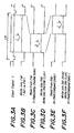
- FM 15 the digital brightness signal derived from the A/D converter 5 is stored in synchronism with the operation of the A/D converter as illustrated in timing charts of Figs. 2A and 2B, and the stored brightness signal is read out with a delay of one field period as shown in Fig. 2C.
- the digital brightness signal is read out of FM 15 at a rate which is a double of the writing clock as shown in timing charts of Figs. 3A-3C. Therefore, the reading out operation is completed within a first half period of one line period H (see Fig. 3C). In this manner, the time axis compression is carried out.
- the digital brightness signal Y read out of the FM 15 is supplied, on one hand, to a delay ring memory (RM) 16 as a right-eye digital image signal (Rch signal), and on the other hand, to shot memory (SM) 17 and double scan conversion 3D display memory (DM) 18 as a left-eye digital image signal (Lch signal).
- RM 16 comprises a plurality of field memories, in an example shown 32 fields memories 19 which are connected as a ring.
- Writing/reading addresses for RM 16 are controlled by an RM/SM address control circuit 20 in accordance with the memory control signal supplied from the timing signal generating circuit 10 and the number n of the delayed fields which is set arbitrarily by controlling the control panel.
- the image signals of successive fields read out of FM 15 are written into successive field memories 19 (Fig. 3D), and at the same time the image signals of successive fields which are delayed by the predetermined number n of fields with respect to the currently written image signal are read out of RM 16 (Fig. 3E).
- the reading out operation is carried out within a last half period of respective horizontal scanning periods H.
- the image signal read out of RM 16 is supplied to SM 17 and DM 18 as the right-eye image signal (Fig. 3F).
- SM 17 stores right-eye and left-eye image signals for displaying a stereoscopic still picture and comprises eight pairs of field memories, i.e. 16 field memories 21 as shown in Fig. 5, each pair storing image signals of one still picture.
- the write/read address of SM 16 is controlled by the RM/SM address control circuit 20 in such a manner that image signals on successive lines of a left-eye image signal of one field derived from FM 15 are stored in one of a pair of field memories within first half periods of successive horizontal scanning periods H, image signals on successive lines of a right-eye image signal of one field which is derived from RM 16 and is delayed by n fields with respect to the left-eye image signal are stored in the other field memory of the relevant pair within second half periods of successive horizontal scanning periods H, and the stored image signals of right-eye and left-eye image signals for one field are read out selectively, the read out image signals being supplied to DM 18 (Fig. 3F).
- DM 18 comprises four field memories, two for one frame (two fields) of left-eye image and two for one frame (two fields) of right-eye image. Under the control of the memory control signals from the timing signal generating circuit 10, the right-eye and left-eye image signals of two fields are alternately written into and read out of DM 18 such that the image signals from FM 15 and RM 16 or the image signals from SM 17 are written or read out in accordance with the selected operation mode.
- image signals of successive lines from FM 15 are written into the left-eye field memory of DM 18 within a first half of successive line periods, and image signals of successive lines of the n-field delayed field from RM 16 are written into the right-eye field memory of DM 16 within a last half of successive field periods.
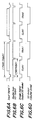
- image signals previously stored in the left-eye field memory and the n-field delayed image signals previously stored in the right-eye field memory are read out in a field sequence as shown in Figs. 6A-6C.
- image signals of successive lines from the left-eye field memory of SM 17 are written into the left-eye field memory of DM 18 within a first half of successive line periods, and image signals of successive lines of the n-field delayed field from the right-eye field memory of SM 17 are written into the right-eye field memory of DM 16 within a last half of successive field periods.
- the image signals stored in the left-eye field memory and the n-field delayed image signals stored in the right-eye field memory are read out in a field sequence as shown in Figs. 7A-7C.
- SM 17 includes eight field memory pairs, it is possible to store the image signals of eight frames after the freezing operation, and thus any one of image signals may be selectively displayed by operating the control panel.
- the image signal read out of DM 18 is supplied via a line interpolation circuit 25 to a D/A converter 26 and is converted into an analog image signal.
- the thus converted analog image signal is supplied via a 75 ⁇ driver 27 to an image signal output terminal 28. It should be noted that this output image signal has horizontal and vertical scanning frequencies which are higher than the normal horizontal and vertical scanning frequencies by two times. In this manner, the 3D display memory 18 performs the double scan converter.
- the line interpolation circuit 25 is operated only when the 3D still picture display mode is selected. In this mode of operation, if image signals of odd and even fields of one frame picture of the moving picture are displayed as a still picture, a moving object might be shifted between the odd and even fields and could not be seen clearly. Therefore, in the present embodiment, the image signals stored in the left-eye and right-eye field memories are alternately read out in a repeated fashion as explained above. However, when the image signal of only one field is used in this manner, the vertical resolution might be deteriorated.
- an image signal of a second field is formed from the image signal of one field (first field) read out of DM 18 in the line interpolation circuit 25, and the first field image signal and the interpolated second field image signal are alternately supplied to the D/A converter 26. In this manner, the vertical resolution can be improved.
- Fig. 8 shows an embodiment of the line interpolator 25.
- the image signal of the first field read out of DM 18 is supplied to one input of an adder 31 as well as to a line memory 32.
- An output signal of the line memory 32 is supplied to the other input terminal of the adder 31. Timings of the writing and reading operation are controlled by the control signals supplied from the timing signal generating circuit 10 such that the interpolated image signal of the second field can be obtained.
- the left-eye and right-eye image signals at the output terminal 28 with a double scan rate are supplied to a single monitor and are displayed thereon.
- the displayed left-eye image is monitored by a left-eye of a user and the right-eye image is exclusively seen by the right-eye, then the monitor can see the stereoscopic image.
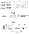
- Fig. 9 shows an embodiment of the stereoscopic image display system comprising the above mentioned image signal processing apparatus according to the invention generally shown by a reference numeral 51.
- the input terminal of the image signal processing apparatus 51 is connected to an image signal input terminal of an image signal supply source 52 comprising video apparatuses such as video tape recorder and video camera.
- video apparatuses such as video tape recorder and video camera.
- the object and video camera are moved relatively in the horizontal direction.
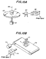
- Fig. 10A illustrates an embodiment of the image signal source 52.
- an object 61 is placed on a turntable 62 which is rotated by a motor 63 about a vertical axis 64 at a given angular velocity, while the image of the object 61 is picked-up by a video camera 65 which is arranged stationarily.
- An image signal generated by the video camera 65 is supplied to a video tape recorder 66.
- Fig. 10B depicts another embodiment of the image signal source according to the invention.
- an object 71 to be picked-up is placed on a belt conveyer 72 which is moved horizontally at a given linear speed by means of a motor 73.
- the object 71 is picked-up by a video camera 74 which is arranged beside the belt conveyer 72.
- An image signal generated by the video camera 74 is directly supplied to the image signal processing apparatus 51.
- the image signal from the video camera may be once stored in a video tape recorder or may be supplied to the image signal processing apparatus 51 by means of any suitable video processor.
- the output signals supplied from the image signal processing apparatus 51 i.e. the HD signal from the HD signal output terminal 11, VD signal from the VD signal output terminal 12 and image signal from the image signal output terminal 28, are supplied to corresponding input terminals of a monitor 53.
- Left-eye image and right-eye image alternately displayed on the monitor 53 at the double scan rate are seen with the aid of polarizing glasses 54.
- the SD signal appearing at the SD signal output terminal 13 of the image signal processing apparatus 51 (Fig. 6D) is supplied to a synchronizing signal input terminal of a shutter driving device 55 to produce a shutter driving signal in synchronism with the SD signal.
- the thus produced shutter driving signal is transmitted to the polarizing glasses 54 by infrared radiation or electromagnetic radiation.
- liquid crystal shutters for right-eye and left-eye provided in the glasses 54 are controlled such that these shutters are alternately opened and closed.
- the user can see the stereoscopic still picture or moving picture.
- a two dimensional (2D) image may be seen in accordance with the image signal from the image signal output apparatus 52.
- a feeling of depth of the monitored three-dimensional image can be controlled by inverting the polarity of the shutter driving signal SD.
- the three-dimensional image display system can be made simple. For instance, when a cut surface of jewel is to be checked, a jewel is placed on the turntable and is rotated thereon, while the image of the jewel is picked-up by the video camera arranged stationarily as illustrated in Fig. 10A.
- the image signal processing apparatus may be advantageously applied to the checking of metal welded portion.
- an X-ray image pick-up camera is arranged fixedly and a welded portion is moved with respect to the camera. Then, the three-dimensional image of the welded portion can be monitored, and thus the welded portion as well as non-welded portion can be checked accurately and easily.
- a patient is picked-up by an X-ray camera while the camera is moved with respect to the patient having a contrast agent injected therein. In this manner, the positional relationship of blood vessels of the patient can be monitored as the three-dimensional image, which is very helpful for diagnosis and cure.
- the number n of delayed fields upon reading the field signal from RM 16 can be adjusted at will with the aid of the control panel, the feeling of stereoscopic vision (three-dimensional effect) can be easily controlled.
- the synchronizing signal is generated by the local synchronizing signal generating circuit 9 and the necessary signals are produced on the basis of this locally generated synchronizing signal. Therefore, even if the synchronizing signal contained in the input image signal is not accurate, it is always possible to obtain the image signal for the stereoscopic image display. Therefore, the stereoscopic image display system can be realized at a relatively low cost.
- TSC time base corrector
- the accurate synchronizing signal is generated, it is possible to process the input image signal having a disturbed synchronizing signal or having no color burst signal. Therefore, it is possible to use a conventional cheap down-converter.
- Fig. 11 is a block diagram showing a second embodiment of the image signal processing apparatus according to the invention. This embodiment differs from the first embodiment only in a point that an image processor 81 for performing the ⁇ correction is arranged between the A/D converter 5 and the field buffer memory 15. The operation of the image processor 18 can be controlled by means of the control panel.
- the image processor 81 by suitably operating the image processor 81, it is possible to selectively display stereoscopic images having corrected ⁇ and non-corrected ⁇ , and these images can be easily compared with each other in addition to the merits of the first embodiment.
- the present invention is not limited to the embodiments explained above, but many alternations and modifications may be conceived by those skilled in the art within the scope of the invention.
- the image signal of NTSC system is processed, but according to the invention, it is also possible to process any kinds of image signals such as PAL image signal, and a compressed image signal such as MPEG.
- the field memory FM 15 may be replaced by a line memory. Also in this case, the compression on time can be performed.
- DM 18 may be formed by two field memories instead of sixteen field memories.
- the image signal from FM 15 or one channel signal from SM 17 is stored in one field memory
- the image signal from RM 16 or the other channel signal from SM 17 is stored in the other field memory.
- the decrease in the vertical resolution can be prevented by the line interpolation circuit 25 like as the 3D still picture display mode.
- the right-eye and left-eye image signals for the 3D still picture display are stored in SM 17 at a field unit.
- these image signals may be stored at frame unit.
- the line interpolation circuit 25 may be omitted.
- the image signals stored in SM 17 may be supplied to a computer by means of a SCSI cable.
- the control panel by operating the control panel, not only the 3D moving and still picture display modes, but also 2D moving picture and still picture display modes may be controlled.
- the 2D moving picture display mode one field memory in DM 18 for the L-channel or R-channel may be read out repeatedly.
- the brightness signal Y is outputted from the 75 ⁇ driver 27 to the image signal output terminal 28, but according to the invention, the 75 ⁇ driver may produce R, G and B color signals.
- the image processor 81 is operated selectively, but it may be operated continuously. Further, the image processor 81 may be provided at the output of the field buffer memory 15 or at the output of the 3D display memory 18. Moreover, the process executed by the image processor 81 is not limited to the gamma correction, but any other process such as Fourier transformation, image interpolation and image compression may be performed. If the image compression is executed, the compression is carried out between the A/D converter 5 and the field buffer memory 15 and the decomposition is performed between the 3D display memory 18 and the D/A converter 26.
- all memories in the field buffer memory 15, delay ring memory 16, shot memory 17, 3D display memory 18 and line interpolation circuit 25 may be constructed by a single rewritable record medium such as a hard disc drive (HDD). Then, the whole image signal processing apparatus according to the invention may be simply installed in a personal computer. In this manner, a cost of the image processing apparatus as well as the whole image display system can be further decreased.
- HDD hard disc drive
- the right-eye and left-eye image signals necessary for displaying the stereoscopic image can be produced from the single input image signal, and therefore the stereoscopic image display system can be realized at a low cost.
Landscapes
- Engineering & Computer Science (AREA)
- Multimedia (AREA)
- Signal Processing (AREA)
- Testing, Inspecting, Measuring Of Stereoscopic Televisions And Televisions (AREA)
Applications Claiming Priority (5)
| Application Number | Priority Date | Filing Date | Title |
|---|---|---|---|
| JP244726/96 | 1996-09-17 | ||
| JP24472696 | 1996-09-17 | ||
| JP174073/97 | 1997-06-30 | ||
| JP17407397 | 1997-06-30 | ||
| PCT/JP1997/003277 WO1998012879A1 (fr) | 1996-09-17 | 1997-09-17 | Unite de traitement de signaux image |
Publications (2)
| Publication Number | Publication Date |
|---|---|
| EP0862340A1 true EP0862340A1 (de) | 1998-09-02 |
| EP0862340A4 EP0862340A4 (de) | 2002-06-12 |
Family
ID=26495809
Family Applications (1)
| Application Number | Title | Priority Date | Filing Date |
|---|---|---|---|
| EP97941185A Withdrawn EP0862340A4 (de) | 1996-09-17 | 1997-09-17 | Bildsignalverarbeitungsgerät |
Country Status (4)
| Country | Link |
|---|---|
| EP (1) | EP0862340A4 (de) |
| AU (1) | AU4318597A (de) |
| TW (1) | TW355901B (de) |
| WO (1) | WO1998012879A1 (de) |
Cited By (1)
| Publication number | Priority date | Publication date | Assignee | Title |
|---|---|---|---|---|
| WO2004082296A1 (en) * | 2003-03-14 | 2004-09-23 | Philips Intellectual Property & Standards Gmbh | Arrangement for generating a 3d video signal |
Families Citing this family (2)
| Publication number | Priority date | Publication date | Assignee | Title |
|---|---|---|---|---|
| CN102948141B (zh) * | 2010-05-28 | 2016-08-10 | 索尼公司 | 图像捕获装置和图像捕获方法 |
| JP2018121314A (ja) * | 2017-01-29 | 2018-08-02 | 大竹技研株式会社 | 平面画像から立体画像を作成する立体化方法 |
Family Cites Families (8)
| Publication number | Priority date | Publication date | Assignee | Title |
|---|---|---|---|---|
| JPS6346091A (ja) * | 1986-08-13 | 1988-02-26 | Nippon Hoso Kyokai <Nhk> | 立体テレビジヨン方式 |
| JPS63181593A (ja) * | 1987-01-22 | 1988-07-26 | Ricoh Co Ltd | 立体映像再生装置 |
| JPH0750944B2 (ja) * | 1987-03-09 | 1995-05-31 | シャープ株式会社 | 電子立体映像装置 |
| WO1995018512A1 (de) * | 1993-12-29 | 1995-07-06 | Leica Ag | Verfahren und vorrichtung zur darstellung von stereoskopischen videobildern auf einem display |
| JPH07212799A (ja) * | 1994-01-18 | 1995-08-11 | Sankyo Seiki Mfg Co Ltd | 立体映像表示装置 |
| KR100358021B1 (ko) * | 1994-02-01 | 2003-01-24 | 산요 덴키 가부시키가이샤 | 2차원영상을3차원영상으로변환시키는방법및입체영상표시시스템 |
| JP2983844B2 (ja) * | 1994-07-14 | 1999-11-29 | 三洋電機株式会社 | 3次元画像変換方法 |
| KR100445619B1 (ko) * | 1996-07-18 | 2004-08-25 | 산요덴키가부시키가이샤 | 2차원 영상을 3차원 영상으로 변환하는 장치 및 방법 |
-
1997
- 1997-09-17 EP EP97941185A patent/EP0862340A4/de not_active Withdrawn
- 1997-09-17 WO PCT/JP1997/003277 patent/WO1998012879A1/ja not_active Ceased
- 1997-09-17 TW TW086113441A patent/TW355901B/zh active
- 1997-09-17 AU AU43185/97A patent/AU4318597A/en not_active Abandoned
Cited By (1)
| Publication number | Priority date | Publication date | Assignee | Title |
|---|---|---|---|---|
| WO2004082296A1 (en) * | 2003-03-14 | 2004-09-23 | Philips Intellectual Property & Standards Gmbh | Arrangement for generating a 3d video signal |
Also Published As
| Publication number | Publication date |
|---|---|
| WO1998012879A1 (fr) | 1998-03-26 |
| TW355901B (en) | 1999-04-11 |
| AU4318597A (en) | 1998-04-14 |
| EP0862340A4 (de) | 2002-06-12 |
Similar Documents
| Publication | Publication Date | Title |
|---|---|---|
| US5684529A (en) | Stereoscopio display using movement direction detection | |
| EP0425985A2 (de) | Stereoskopisches bilderzeugendes System | |
| JPH09507349A (ja) | 表示装置上に立体ビデオ映像を表示するための方法及び装置 | |
| KR100221742B1 (ko) | 영상표시장치 | |
| JP3262893B2 (ja) | 内視鏡用画像表示装置 | |
| EP0862340A1 (de) | Bildsignalverarbeitungsgerät | |
| JPH08223603A (ja) | 三次元ビデオ画像を表示する方法及び装置 | |
| JPH0193986A (ja) | 立体テロップ付撮像装置 | |
| JPS6261493A (ja) | 立体視用画像表示装置 | |
| JP2002095017A (ja) | 立体映像表示システム | |
| US5956082A (en) | Video signal processing apparatus | |
| JPS63181593A (ja) | 立体映像再生装置 | |
| KR100215436B1 (ko) | 입체영상재생장치 | |
| JPS6346091A (ja) | 立体テレビジヨン方式 | |
| JP3087236B2 (ja) | 立体視画像の合成表示装置 | |
| JPWO1998012879A1 (ja) | 映像信号処理装置 | |
| JPH07322300A (ja) | 映像信号変換方法及び装置並びに立体映像観賞装置 | |
| Lipton | Stereoscopic real-time and multiplexed video system | |
| JPH07163566A (ja) | 超音波診断装置 | |
| JPH01165293A (ja) | 立体映像装置 | |
| JPS62145993A (ja) | 立体画像観視装置 | |
| JP2602236B2 (ja) | 立体テレビジョン信号の処理装置 | |
| JP2918049B2 (ja) | ピクチャ・イン・ピクチャのための記憶方法 | |
| US7106384B1 (en) | Method and device for simultaneously representing at least a first and a second sequence of pictures in an overall picture | |
| JP2656254B2 (ja) | 立体画像用映像信号発生装置 |
Legal Events
| Date | Code | Title | Description |
|---|---|---|---|
| PUAI | Public reference made under article 153(3) epc to a published international application that has entered the european phase |
Free format text: ORIGINAL CODE: 0009012 |
|
| 17P | Request for examination filed |
Effective date: 19980608 |
|
| AK | Designated contracting states |
Kind code of ref document: A1 Designated state(s): DE FR GB |
|
| A4 | Supplementary search report drawn up and despatched |
Effective date: 20020429 |
|
| AK | Designated contracting states |
Kind code of ref document: A4 Designated state(s): DE FR GB |
|
| RIC1 | Information provided on ipc code assigned before grant |
Free format text: 7H 04N 13/00 A |
|
| STAA | Information on the status of an ep patent application or granted ep patent |
Free format text: STATUS: THE APPLICATION IS DEEMED TO BE WITHDRAWN |
|
| 18D | Application deemed to be withdrawn |
Effective date: 20020401 |