EP0860592A1 - Kühlflüssigkeitskreislauf eines Kraftfahrzeug-Antriebsaggregates - Google Patents
Kühlflüssigkeitskreislauf eines Kraftfahrzeug-Antriebsaggregates Download PDFInfo
- Publication number
- EP0860592A1 EP0860592A1 EP98100652A EP98100652A EP0860592A1 EP 0860592 A1 EP0860592 A1 EP 0860592A1 EP 98100652 A EP98100652 A EP 98100652A EP 98100652 A EP98100652 A EP 98100652A EP 0860592 A1 EP0860592 A1 EP 0860592A1
- Authority
- EP
- European Patent Office
- Prior art keywords
- coolant
- heat exchanger
- valve
- additional
- air
- Prior art date
- Legal status (The legal status is an assumption and is not a legal conclusion. Google has not performed a legal analysis and makes no representation as to the accuracy of the status listed.)
- Granted
Links
- 238000001816 cooling Methods 0.000 title description 3
- 239000002826 coolant Substances 0.000 claims abstract description 100
- 239000000110 cooling liquid Substances 0.000 claims description 8
- 239000010720 hydraulic oil Substances 0.000 claims description 6
- 239000000203 mixture Substances 0.000 claims 1
- 238000002485 combustion reaction Methods 0.000 description 7
- 239000012208 gear oil Substances 0.000 description 3
- 230000005540 biological transmission Effects 0.000 description 2
- 238000011144 upstream manufacturing Methods 0.000 description 2
- 229910001369 Brass Inorganic materials 0.000 description 1
- 239000010951 brass Substances 0.000 description 1
- 238000010586 diagram Methods 0.000 description 1
- 230000000694 effects Effects 0.000 description 1
- 238000010438 heat treatment Methods 0.000 description 1
- 239000003921 oil Substances 0.000 description 1
- 229910001220 stainless steel Inorganic materials 0.000 description 1
- 239000010935 stainless steel Substances 0.000 description 1
Images
Classifications
-
- F—MECHANICAL ENGINEERING; LIGHTING; HEATING; WEAPONS; BLASTING
- F01—MACHINES OR ENGINES IN GENERAL; ENGINE PLANTS IN GENERAL; STEAM ENGINES
- F01P—COOLING OF MACHINES OR ENGINES IN GENERAL; COOLING OF INTERNAL-COMBUSTION ENGINES
- F01P7/00—Controlling of coolant flow
- F01P7/14—Controlling of coolant flow the coolant being liquid
- F01P7/16—Controlling of coolant flow the coolant being liquid by thermostatic control
- F01P7/165—Controlling of coolant flow the coolant being liquid by thermostatic control characterised by systems with two or more loops
-
- F—MECHANICAL ENGINEERING; LIGHTING; HEATING; WEAPONS; BLASTING
- F01—MACHINES OR ENGINES IN GENERAL; ENGINE PLANTS IN GENERAL; STEAM ENGINES
- F01P—COOLING OF MACHINES OR ENGINES IN GENERAL; COOLING OF INTERNAL-COMBUSTION ENGINES
- F01P3/00—Liquid cooling
- F01P3/18—Arrangements or mounting of liquid-to-air heat-exchangers
- F01P2003/182—Arrangements or mounting of liquid-to-air heat-exchangers with multiple heat-exchangers
-
- F—MECHANICAL ENGINEERING; LIGHTING; HEATING; WEAPONS; BLASTING
- F01—MACHINES OR ENGINES IN GENERAL; ENGINE PLANTS IN GENERAL; STEAM ENGINES
- F01P—COOLING OF MACHINES OR ENGINES IN GENERAL; COOLING OF INTERNAL-COMBUSTION ENGINES
- F01P3/00—Liquid cooling
- F01P3/18—Arrangements or mounting of liquid-to-air heat-exchangers
- F01P2003/185—Arrangements or mounting of liquid-to-air heat-exchangers arranged in parallel
-
- F—MECHANICAL ENGINEERING; LIGHTING; HEATING; WEAPONS; BLASTING
- F01—MACHINES OR ENGINES IN GENERAL; ENGINE PLANTS IN GENERAL; STEAM ENGINES
- F01P—COOLING OF MACHINES OR ENGINES IN GENERAL; COOLING OF INTERNAL-COMBUSTION ENGINES
- F01P3/00—Liquid cooling
- F01P3/18—Arrangements or mounting of liquid-to-air heat-exchangers
- F01P2003/187—Arrangements or mounting of liquid-to-air heat-exchangers arranged in series
-
- F—MECHANICAL ENGINEERING; LIGHTING; HEATING; WEAPONS; BLASTING
- F01—MACHINES OR ENGINES IN GENERAL; ENGINE PLANTS IN GENERAL; STEAM ENGINES
- F01P—COOLING OF MACHINES OR ENGINES IN GENERAL; COOLING OF INTERNAL-COMBUSTION ENGINES
- F01P7/00—Controlling of coolant flow
- F01P7/14—Controlling of coolant flow the coolant being liquid
- F01P2007/143—Controlling of coolant flow the coolant being liquid using restrictions
-
- F—MECHANICAL ENGINEERING; LIGHTING; HEATING; WEAPONS; BLASTING
- F01—MACHINES OR ENGINES IN GENERAL; ENGINE PLANTS IN GENERAL; STEAM ENGINES
- F01P—COOLING OF MACHINES OR ENGINES IN GENERAL; COOLING OF INTERNAL-COMBUSTION ENGINES
- F01P2025/00—Measuring
- F01P2025/08—Temperature
- F01P2025/50—Temperature using two or more temperature sensors
-
- F—MECHANICAL ENGINEERING; LIGHTING; HEATING; WEAPONS; BLASTING
- F01—MACHINES OR ENGINES IN GENERAL; ENGINE PLANTS IN GENERAL; STEAM ENGINES
- F01P—COOLING OF MACHINES OR ENGINES IN GENERAL; COOLING OF INTERNAL-COMBUSTION ENGINES
- F01P2060/00—Cooling circuits using auxiliaries
- F01P2060/04—Lubricant cooler
-
- F—MECHANICAL ENGINEERING; LIGHTING; HEATING; WEAPONS; BLASTING
- F01—MACHINES OR ENGINES IN GENERAL; ENGINE PLANTS IN GENERAL; STEAM ENGINES
- F01P—COOLING OF MACHINES OR ENGINES IN GENERAL; COOLING OF INTERNAL-COMBUSTION ENGINES
- F01P2060/00—Cooling circuits using auxiliaries
- F01P2060/04—Lubricant cooler
- F01P2060/045—Lubricant cooler for transmissions
-
- F—MECHANICAL ENGINEERING; LIGHTING; HEATING; WEAPONS; BLASTING
- F01—MACHINES OR ENGINES IN GENERAL; ENGINE PLANTS IN GENERAL; STEAM ENGINES
- F01P—COOLING OF MACHINES OR ENGINES IN GENERAL; COOLING OF INTERNAL-COMBUSTION ENGINES
- F01P2060/00—Cooling circuits using auxiliaries
- F01P2060/06—Retarder
Definitions
- the invention relates to a coolant circuit of a motor vehicle drive unit with an air-coolant heat exchanger as well with at least one additional heat exchanger in which another medium, in particular hydraulic oil, can be tempered by the circulating coolant is, in the return of the air-coolant heat exchanger downstream of a branch to the additional heat exchanger is the coolant volume flow influencing valve is provided.
- A is known Coolant circuit of this type from EP 0 177 025 A2.
- the additional heat exchanger has an increased flow resistance is in the coolant circuit according to EP 0 177 025 A2 in Return of the air-coolant heat exchanger downstream of the branch to the additional heat exchanger that said the coolant volume flow influencing valve provided to also in this line branch to create certain flow resistance and thus ensure that at least a subset of the coolant flow over the other Line branch, namely via the additional heat exchanger.
- This known arrangement may well be suitable for certain applications may be sufficient, but in other cases it may be desirable to have one particularly intensive cooling of the additional medium in the additional heat exchanger to achieve.
- this additional medium can also coexist a hydraulic oil, for example in a turbocharger compressed and thus heated intake air designed as an internal combustion engine Act motor vehicle drive unit.
- Air-coolant heat exchanger here called additional cooler
- Air-coolant heat exchanger here called additional cooler
- the additional cooler forms a further flow resistance, so that the simple downstream of the branch to the additional heat exchanger provided and valve influencing the coolant volume flow, which is designed as a throttle in the above-mentioned EP 0 177 025 A2 is no longer sufficient to have a sufficient flow of coolant at all by the additional heat exchanger and by the upstream of this To lead additional cooler.
- this (additional) valve which downstream of the Branch to the additional heat exchanger is provided and the coolant volume flow influenced by the air-coolant heat exchanger, formed as a throttle valve biased in the closed position.
- a valve of this type flows, in particular, at a low delivery rate the pump provided in the coolant circuit and at at least partially opened thermostatic valve (so that coolant at all through the air-coolant heat exchanger) always a sufficient flow of coolant through the additional heat exchanger, whereas almost no coolant flow through the then in the substantially closed throttle valve arrives.
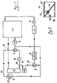
- reference numeral 1 designates an internal combustion engine functioning as a motor vehicle drive unit, which is water-cooled and the cooling liquid of which, as usual, can be recooled in an air-coolant heat exchanger 2, the flow of which is identified by the reference number 19.
- the cooling liquid is conveyed by a cooling liquid pump 3, which, as usual, is preceded by a thermostatic valve 4, with the aid of which the cooling liquid is either via the heat exchanger 2 or in the so-called small circuit "can be circulated bypassing the air-coolant heat exchanger 2.
- the direction of flow of the coolant is indicated by arrows.
- a heating heat exchanger 5 is provided in the coolant circuit, which is preceded by a control valve 6.
- Reference number 7 also denotes a conventional expansion tank, which is connected to the flow 19 of the air-coolant heat exchanger 2 is.
- a coolant bypass leads through this expansion tank 7 21 through, which branches from the lead 19, and which within the expansion tank 7 a so-called.
- Throttle branch 22 has.
- This so-called throttle branch 22, one opposite the coolant branch line 20 has a significantly smaller flow cross section has, the expansion tank 7 is thus as usual connected the entire coolant circuit.
- Another component of the coolant circuit is an additional heat exchanger 8, about the u. a. recooled coolant (from a branch 20 coming in the return 12 of the air-coolant heat exchanger 2) is feasible, and in which this is another medium, such as hydraulic oil / gear oil can cool.
- This additional heat exchanger 8 is also a thermostatic valve 9 upstream, in which the recooled coolant with non-recooled coolant - from said coolant bypass 21 coming - can be mixed in order in the additional heat exchanger 8 a desired temperature control of the one guided by it To be able to adjust the medium (hydraulic oil / gear oil).
- additional cooler 10 In order to cool the additional heat exchanger 8 particularly intensively To enable medium is the air-coolant heat exchanger 2 another so-called additional cooler 10 is connected downstream.
- This additional cooler 10 is thus in the lead 11 of the additional heat exchanger 8, in which the thermostatic valve 9 is provided and is from the return 12 of the Lutt coolant heat exchanger 2 from the branch 20 with coolant provided.
- the auxiliary cooler 10 which also functions as an air-coolant heat exchanger is formed, preferably forms with the actual air-coolant heat exchanger 2 a structural unit, as in the not previously published German patent application 196 37 818 is described.
- valve 13 does not exist, because of the flow resistance of the Additional cooler 10 and the additional heat exchanger 8 namely almost the complete exits from the air-coolant heat exchanger 2 Coolant flow directly (via the return 12) to the thermostatic valve 4 arrive, so that the additional heat exchanger 8 not at all would be flowed through.
- a suitable throttling effect of the valve 13 it is possible, however, a more or less large proportion of the Coolant flow also via the additional heat exchanger 8 to the coolant pump 3 attributed.
- valve 13 Only satisfactorily (additional) valve 13 if this Valve 13 as a throttle valve pretensioned in the closed position (cf. Fig. 2, reference numeral 14) is formed.
- this valve 13 or the corresponding throttle valve remains 14 almost closed, so that (when the thermostatic valve is open 4) the air-coolant heat exchanger 2 as desired after flowing through the coolant leaving it almost completely passed through the additional cooler 10 and via the additional heat exchanger 8 becomes.
- valve 13 designed as a throttle valve 14 is opened ever further, so that then the drive unit 1 or the internal combustion engine 1 on direct Ways (via the return 12) with a sufficient amount of im Air-coolant heat exchanger 2 recooled coolant supplied can be.
- Fig. 2 shows a cross section through the as biased in the closed position Throttle valve 14 formed valve 13, which with its valve housing 15 when the air-coolant heat exchanger 2 and the As already briefly mentioned, additional cooler 10 form a structural unit, preferably in the return nozzle of the air-coolant heat exchanger, not shown 2, to which the return 12 connects, can be arranged can.
- the throttle valve 14 is located on the valve housing 15 biasing torsion spring 16 biased, the throttle valve 14 over its axis of rotation 17 is desaxially mounted in the valve housing 15.
- acts the valve 13 or the throttle valve 14 with regard to coolant flow direction shown by an arrow 18 as Back pressure flap with respect to this flow due to said Desaxing, depending on the dynamic pressure, the desired opening of the throttle valve 14 or the valve 13 takes place.
- this valve 13 remains fully or partially closed and leads then, depending on the dynamic pressure, the desired throttle function.
- the throttle valve 14 itself can be made of brass, while the flap housing 15 and the torsion spring 16, the spring characteristics of which determine the throttle behavior of the valve 13, can be made of stainless steel.
- this and a large number of further details can be designed quite differently from the exemplary embodiment shown, without leaving the content of the patent claims.
Landscapes
- Engineering & Computer Science (AREA)
- Chemical & Material Sciences (AREA)
- Combustion & Propulsion (AREA)
- Mechanical Engineering (AREA)
- General Engineering & Computer Science (AREA)
- Heat-Exchange Devices With Radiators And Conduit Assemblies (AREA)
- Air-Conditioning For Vehicles (AREA)
Abstract
Description

Ebenfalls wie üblich ist im Kühlflüssigkeitskreislauf ein Heizungswärmetauscher 5 vorgesehen, dem ein Regelventil 6 vorgeschaltet ist.
Die Drosselklappe 14 selbst kann in Messing ausgeführt sein, während das Klappengehäuse 15 und die Drehfeder 16, deren Federcharakteristik des Drosselverhalten des Ventiles 13 bestimmt, in Edelstahl ausgeführt sein können. Jedoch kann dies sowie eine Vielzahl weiterer Details durchaus abweichend vom gezeigten Ausführungsbeispiel gestaltet sein, ohne den Inhalt der Patentansprüche zu verlassen. Stets erhält man mit geeigneter Auslegung der Vorspannung der Drosselklappe 14 in Schließstellung (beispielsweise durch die besagte Drehfeder 16) eine optimale Aufteilung des Kühlmittelstroms einerseits auf den direkt zum Thermostatventil 4 führenden Rücklauf 12, als auch andererseits auf den über den Zusatzkühler 10 sowie den Zusatzwärmetauscher 8 zur Kühlflüssigkeitspumpe 3 geführten Leitungszweig.
Claims (4)
- Kühlflüssigkeitskreislauf eines Kraftfahrzeug-Antriebsaggregates mit einem Luft-Kühlflüssigkeits-Wärmetauscher (2) sowie mit zumindest einem Zusatzwärmetauscher (8), in welchem ein weiteres Medium, insbesondere Hydrauliköl, durch die umgewälzte Kühlflüssigkeit temperierbar ist, wobei im Rücklauf (12) des Luft-Kühlflüssigkeits-Wärmetauschers (2) stromab eines Abzweigs (20) zum Zusatzwärmetauscher (8) ein den Kühlflüssigkeits-Volumenstrom beeinflussendes Ventil (13) vorgesehen ist,
dadurch gekennzeichnet, daß das Ventil (13) als eine in Schließstellung vorgespannte Drosselklappe (14) ausgebildet ist und daß im Vorlauf (11) zum Zusatzwärmetauscher (8) ein Zusatzkühler (10) für die Kühlflüssigkeit vorgesehen ist. - Kühlflüssigkeitskreislauf nach Anspruch 1,
dadurch gekennzeichnet, daß der Zusatzkühler (10) mit dem Luft-Kühlflüssigkeits-Wärmetauscher (2) eine Baueinheit bildet und die Drosselklappe (14) im Rücklaufstutzen des Luft-Kühlflüssigkeits-Wärmetauschers (2) vorgesehen ist. - Kühlflüssigkeitskreislauf nach Anspruch 1 oder 2,
dadurch gekennzeichnet, daß mittels eines im Vorlauf (11) zum Zusatzwärmetauscher (8) vorgesehenen Thermostatventiles (9) diesem im Zusatzkühler (10) rückgekühlte oder vom Vorlauf (19) zum Luft-Kühlflüssigkeits-Wärmetauscher (2) abgezweigte und somit nicht rückgekühlte Kühlflüssigkeit, oder eine Mischung hiervon zuführbar ist. - Kühlflüssigkeitskreislauf nach einem der vorangegangenen Ansprüche,
dadurch gekennzeichnet, daß die in Schließstellung vorgespannte Drosselklappe (14) federbelastet und in ihrem Klappengehäuse (15) desachsiert gelagert ist.
Applications Claiming Priority (2)
| Application Number | Priority Date | Filing Date | Title |
|---|---|---|---|
| DE19706800 | 1997-02-20 | ||
| DE19706800A DE19706800A1 (de) | 1997-02-20 | 1997-02-20 | Kühlflüssigkeitskreislauf eines Kraftfahrzeug-Antriebsaggregates |
Publications (2)
| Publication Number | Publication Date |
|---|---|
| EP0860592A1 true EP0860592A1 (de) | 1998-08-26 |
| EP0860592B1 EP0860592B1 (de) | 2002-04-17 |
Family
ID=7820981
Family Applications (1)
| Application Number | Title | Priority Date | Filing Date |
|---|---|---|---|
| EP98100652A Expired - Lifetime EP0860592B1 (de) | 1997-02-20 | 1998-01-15 | Kühlflüssigkeitskreislauf eines Kraftfahrzeug-Antriebsaggregates |
Country Status (2)
| Country | Link |
|---|---|
| EP (1) | EP0860592B1 (de) |
| DE (2) | DE19706800A1 (de) |
Cited By (6)
| Publication number | Priority date | Publication date | Assignee | Title |
|---|---|---|---|---|
| GB2366365A (en) * | 2000-08-26 | 2002-03-06 | Land Rover Group Ltd | Engine Cooling system |
| EP1083308A3 (de) * | 1999-09-09 | 2003-01-22 | Dr.Ing. h.c.F. Porsche Aktiengesellschaft | Kühleinrichtung für eine Brennkraftmaschine |
| WO2005038209A1 (en) * | 2003-10-15 | 2005-04-28 | Volvo Lastvagnar Ab | Arrangement for cooling a vehicle component |
| EP1998021A2 (de) | 2007-05-30 | 2008-12-03 | Bayerische Motoren Werke Aktiengesellschaft | Kühlsystem für eine Brennkraftmaschine |
| CN101839327B (zh) * | 2009-02-04 | 2015-05-13 | 福特环球技术公司 | 加热变速器液的方法及系统 |
| CN110914524A (zh) * | 2017-08-08 | 2020-03-24 | 奥迪股份公司 | 用于运行机动车的驱动设备的方法以及相应的驱动设备 |
Families Citing this family (1)
| Publication number | Priority date | Publication date | Assignee | Title |
|---|---|---|---|---|
| DE10035480A1 (de) * | 2000-07-21 | 2002-01-31 | Zahnradfabrik Friedrichshafen | Schiffsgetriebe mit Heizvorrichtung |
Citations (4)
| Publication number | Priority date | Publication date | Assignee | Title |
|---|---|---|---|---|
| US1511204A (en) * | 1920-04-19 | 1924-10-07 | Fred E Aseltine | Cooling system for internal-combustion engines |
| JPS588221A (ja) * | 1981-07-03 | 1983-01-18 | Mazda Motor Corp | 水冷式エンジンの冷却装置 |
| EP0177025A2 (de) | 1984-10-05 | 1986-04-09 | Deere & Company | Kühlsystem |
| FR2682160A1 (fr) * | 1991-10-07 | 1993-04-09 | Renault Vehicules Ind | Systeme de refroidissement pour moteur a combustion interne comportant deux parties distinctes de radiateur. |
Family Cites Families (16)
| Publication number | Priority date | Publication date | Assignee | Title |
|---|---|---|---|---|
| GB310750A (en) * | 1929-01-12 | 1929-05-02 | Harry Taylor Mcintosh | Apparatus for controlling the circulation of cooling water in internal combustion engines |
| DE607229C (de) * | 1931-11-13 | 1934-12-19 | Robert Bosch Akt Ges | Selbsttaetige Drosselklappe fuer Ansaugeleitungen von Brennkraftmaschinen |
| DE632153C (de) * | 1935-03-14 | 1936-07-03 | Franz Wilhelm Sieber Dr | Regelungsvorrichtung fuer den Kuehlmittellauf einer Brennkraftmaschine |
| DE766237C (de) * | 1938-02-17 | 1952-04-21 | Sueddeutsche Kuehler Behr | Fluessigkeitsgekuehlter OElkuehler fuer Brennkraftmaschinen mit Heisskuehlung |
| DE754272C (de) * | 1940-11-10 | 1953-08-17 | Hans Windhoff App Und Maschine | Kuehlanlage fuer wassergekuehlte Brennkraftmaschinen mit einem Haupt-, einem Sonderkuehler und einem Waermeaustauscher zur Kuehlung von OEl |
| US2670933A (en) * | 1950-02-24 | 1954-03-02 | Thomas J Bay | Engine cooling apparatus |
| DE1714198U (de) * | 1955-10-21 | 1955-12-29 | Auto Union Gmbh | Thermostat insbesondere fuer kraftfahrzeugmotoren mit thermosyphonkuehlung. |
| SE383401B (sv) * | 1973-06-08 | 1976-03-08 | Saab Scania Ab | Anordning vid backventiler av det slag som har ett ventilhus med rakt genomlopp och med ett cirkulert ventilsete anordnat lengs ett genomloppets symmetrilinje korsande plan, och ett spjell, som er vridbart m.m |
| GB2088529A (en) * | 1979-02-21 | 1982-06-09 | Foster Wheeler Power Prod | Damper system |
| DE3047672A1 (de) * | 1980-12-18 | 1982-07-22 | Aktiengesellschaft Adolph Saurer, 9320 Arbon | Kuehleinrichtung zur kuehlung einer brennkraftmaschine und der ladeluft |
| DE8121873U1 (de) * | 1981-07-25 | 1982-11-11 | MSR Armaturen AG, 1110 Morges, Vaud | "rueckschlagklappe" |
| DE3131162A1 (de) * | 1981-08-06 | 1983-04-28 | Leybold-Heraeus GmbH, 5000 Köln | Drosselklappe mit genauer einstellung des durchflussspaltes fuer vakuumtechnische anlagen |
| DE4104093A1 (de) * | 1991-02-11 | 1992-08-13 | Behr Gmbh & Co | Kuehlanlage fuer ein fahrzeug mit verbrennungsmotor |
| DE9110034U1 (de) * | 1991-08-14 | 1991-09-26 | ABB Patent GmbH, 6800 Mannheim | Kühlsystem für einen brauchwassergekühlten Stromrichter |
| DE4304649A1 (de) * | 1993-02-16 | 1994-09-01 | Alfons Dr Uhl | Selbsttätige Absperrvorrichtung für ein gasführendes Rohr |
| DE19526144B4 (de) * | 1995-07-18 | 2008-10-23 | Pierburg Gmbh | Anordnung einer Drosselklappe |
-
1997
- 1997-02-20 DE DE19706800A patent/DE19706800A1/de not_active Withdrawn
-
1998
- 1998-01-15 EP EP98100652A patent/EP0860592B1/de not_active Expired - Lifetime
- 1998-01-15 DE DE59803811T patent/DE59803811D1/de not_active Expired - Lifetime
Patent Citations (4)
| Publication number | Priority date | Publication date | Assignee | Title |
|---|---|---|---|---|
| US1511204A (en) * | 1920-04-19 | 1924-10-07 | Fred E Aseltine | Cooling system for internal-combustion engines |
| JPS588221A (ja) * | 1981-07-03 | 1983-01-18 | Mazda Motor Corp | 水冷式エンジンの冷却装置 |
| EP0177025A2 (de) | 1984-10-05 | 1986-04-09 | Deere & Company | Kühlsystem |
| FR2682160A1 (fr) * | 1991-10-07 | 1993-04-09 | Renault Vehicules Ind | Systeme de refroidissement pour moteur a combustion interne comportant deux parties distinctes de radiateur. |
Non-Patent Citations (2)
| Title |
|---|
| "ENGINE/TRANSMISSION COOLING SYSTEM", RESEARCH DISCLOSURE, no. 377, 1 September 1995 (1995-09-01), pages 589, XP000536184 * |
| PATENT ABSTRACTS OF JAPAN vol. 007, no. 081 (M - 205) 5 April 1983 (1983-04-05) * |
Cited By (10)
| Publication number | Priority date | Publication date | Assignee | Title |
|---|---|---|---|---|
| EP1083308A3 (de) * | 1999-09-09 | 2003-01-22 | Dr.Ing. h.c.F. Porsche Aktiengesellschaft | Kühleinrichtung für eine Brennkraftmaschine |
| GB2366365A (en) * | 2000-08-26 | 2002-03-06 | Land Rover Group Ltd | Engine Cooling system |
| GB2366365B (en) * | 2000-08-26 | 2004-07-21 | Land Rover Group Ltd | Engine Cooling Systems |
| WO2005038209A1 (en) * | 2003-10-15 | 2005-04-28 | Volvo Lastvagnar Ab | Arrangement for cooling a vehicle component |
| US7210522B2 (en) | 2003-10-15 | 2007-05-01 | Volvo Lastvagnar Ab | Arrangement for cooling a vehicle component |
| EP1998021A2 (de) | 2007-05-30 | 2008-12-03 | Bayerische Motoren Werke Aktiengesellschaft | Kühlsystem für eine Brennkraftmaschine |
| EP1998021A3 (de) * | 2007-05-30 | 2012-05-02 | Bayerische Motoren Werke Aktiengesellschaft | Kühlsystem für eine Brennkraftmaschine |
| EP1998020A3 (de) * | 2007-05-30 | 2012-05-02 | Bayerische Motoren Werke Aktiengesellschaft | Kühlsystem für eine Brennkraftmaschine |
| CN101839327B (zh) * | 2009-02-04 | 2015-05-13 | 福特环球技术公司 | 加热变速器液的方法及系统 |
| CN110914524A (zh) * | 2017-08-08 | 2020-03-24 | 奥迪股份公司 | 用于运行机动车的驱动设备的方法以及相应的驱动设备 |
Also Published As
| Publication number | Publication date |
|---|---|
| DE59803811D1 (de) | 2002-05-23 |
| DE19706800A1 (de) | 1998-08-27 |
| EP0860592B1 (de) | 2002-04-17 |
Similar Documents
| Publication | Publication Date | Title |
|---|---|---|
| DE102010025733B4 (de) | Wärmetauschsysteme für Kraftfahrzeuge | |
| DE102011052454B4 (de) | Verfahren zur steuerung eines zwischenkühlers und ein kühlsystem eines fahrzeugs | |
| DE102014215074B4 (de) | Temperieranordnung für Getriebeöl eines Kraftfahrzeugs sowie Verfahren zum Temperieren von Getriebeöl eines Kraftfahrzeugs | |
| DE69606964T2 (de) | Fahrzeugzusatzheizung unter Verwendung des Klimakreislaufes | |
| DE10311188B4 (de) | Verfahren und Vorrichtung zur bedarfsgerechten Kühlung von Verbrennungskraftmaschinen unter Verwendung eines Bypassventils und mindestens einer Wärmesenke | |
| EP2218887B1 (de) | Kühlsystem für ein Kraftfahrzeug | |
| DE102010035174A1 (de) | Kühlsystem für ein Fahrzeug mit einem Abgasrückführungssystem und Verfahren zur Kühlung eines Fahrzeugs mit einem Abgasrückführungssystem | |
| EP2336538A1 (de) | Einrichtung zur Abgasrückführung sowie Verfahren zur Erwärmung eines Kühlmediums einer Brennkraftmaschine und Verwendung der Einrichtung zur Abgasrückführung | |
| DE102005048286B4 (de) | Verfahren zum Betrieb eines Kühlsystems für eine Verbrennungskraftmaschine | |
| EP1702820B1 (de) | Kühlkreislauf mit einer hydrodynamischen Bremse | |
| DE102015201242B4 (de) | Regelmittel zur Steuerung der Kühlmittelströme eines Split-Kühlsystems | |
| DE102009032647A1 (de) | Kühlsystem für eine Verbrennungskraftmaschine | |
| EP0718133A1 (de) | Heizsystem, insbesondere für Kraftfahrzeuge | |
| DE4446152C2 (de) | Heizsystem, insbesondere für Kraftfahrzeuge | |
| DE102008004161A1 (de) | Verfahren zum Betreiben einer Brennkraftmaschine | |
| EP0860592B1 (de) | Kühlflüssigkeitskreislauf eines Kraftfahrzeug-Antriebsaggregates | |
| EP3470714B1 (de) | Ventil zum einstellen eines kühlfluidflusses zur kolbenkühlung | |
| DE10302170A1 (de) | Kühlmittelkreislauf für eine Brennkraftmaschine | |
| DE19834575C5 (de) | Drehschieberventil | |
| EP0885351B1 (de) | Antriebseinheit mit einem motor und einem retarder | |
| DE10143109B4 (de) | Verfahren und Vorrichtung zur Einstellung definierter Kühlmittelströme in Kühlsystemen von Brennkraftmaschinen in Kraftfahrzeugen | |
| DE10155337A1 (de) | Kühlkreislauf | |
| DE19746773A1 (de) | Klimatisierungsvorrichtung für Fahrzeuge mit einer Heizschleife, die einen Verstellkompressor umfaßt | |
| DE10241228A1 (de) | Kühlsystem für ein Kraftfahrzeug | |
| DE2935589A1 (de) | Fahrzeugantrieb |
Legal Events
| Date | Code | Title | Description |
|---|---|---|---|
| PUAI | Public reference made under article 153(3) epc to a published international application that has entered the european phase |
Free format text: ORIGINAL CODE: 0009012 |
|
| AK | Designated contracting states |
Kind code of ref document: A1 Designated state(s): DE FR GB |
|
| AX | Request for extension of the european patent |
Free format text: AL;LT;LV;MK;RO;SI |
|
| 17P | Request for examination filed |
Effective date: 19980915 |
|
| AKX | Designation fees paid |
Free format text: DE FR GB |
|
| RBV | Designated contracting states (corrected) |
Designated state(s): DE FR GB |
|
| 17Q | First examination report despatched |
Effective date: 20000925 |
|
| GRAG | Despatch of communication of intention to grant |
Free format text: ORIGINAL CODE: EPIDOS AGRA |
|
| GRAG | Despatch of communication of intention to grant |
Free format text: ORIGINAL CODE: EPIDOS AGRA |
|
| GRAH | Despatch of communication of intention to grant a patent |
Free format text: ORIGINAL CODE: EPIDOS IGRA |
|
| GRAH | Despatch of communication of intention to grant a patent |
Free format text: ORIGINAL CODE: EPIDOS IGRA |
|
| REG | Reference to a national code |
Ref country code: GB Ref legal event code: IF02 |
|
| GRAA | (expected) grant |
Free format text: ORIGINAL CODE: 0009210 |
|
| AK | Designated contracting states |
Kind code of ref document: B1 Designated state(s): DE FR GB |
|
| GBT | Gb: translation of ep patent filed (gb section 77(6)(a)/1977) |
Effective date: 20020417 |
|
| REF | Corresponds to: |
Ref document number: 59803811 Country of ref document: DE Date of ref document: 20020523 |
|
| ET | Fr: translation filed | ||
| ET | Fr: translation filed | ||
| PLBE | No opposition filed within time limit |
Free format text: ORIGINAL CODE: 0009261 |
|
| STAA | Information on the status of an ep patent application or granted ep patent |
Free format text: STATUS: NO OPPOSITION FILED WITHIN TIME LIMIT |
|
| 26N | No opposition filed |
Effective date: 20030120 |
|
| PGFP | Annual fee paid to national office [announced via postgrant information from national office to epo] |
Ref country code: DE Payment date: 20110224 Year of fee payment: 14 |
|
| PGFP | Annual fee paid to national office [announced via postgrant information from national office to epo] |
Ref country code: FR Payment date: 20120214 Year of fee payment: 15 |
|
| PGFP | Annual fee paid to national office [announced via postgrant information from national office to epo] |
Ref country code: GB Payment date: 20120125 Year of fee payment: 15 |
|
| PG25 | Lapsed in a contracting state [announced via postgrant information from national office to epo] |
Ref country code: DE Free format text: LAPSE BECAUSE OF NON-PAYMENT OF DUE FEES Effective date: 20120801 |
|
| REG | Reference to a national code |
Ref country code: DE Ref legal event code: R119 Ref document number: 59803811 Country of ref document: DE Effective date: 20120801 |
|
| GBPC | Gb: european patent ceased through non-payment of renewal fee |
Effective date: 20130115 |
|
| REG | Reference to a national code |
Ref country code: FR Ref legal event code: ST Effective date: 20130930 |
|
| PG25 | Lapsed in a contracting state [announced via postgrant information from national office to epo] |
Ref country code: GB Free format text: LAPSE BECAUSE OF NON-PAYMENT OF DUE FEES Effective date: 20130115 Ref country code: FR Free format text: LAPSE BECAUSE OF NON-PAYMENT OF DUE FEES Effective date: 20130131 |