EP0860409A2 - Einrichtung zum Umsetzen von auf einem Kompostierfeld gelagertem, verrottbarem Gut - Google Patents
Einrichtung zum Umsetzen von auf einem Kompostierfeld gelagertem, verrottbarem Gut Download PDFInfo
- Publication number
- EP0860409A2 EP0860409A2 EP98101732A EP98101732A EP0860409A2 EP 0860409 A2 EP0860409 A2 EP 0860409A2 EP 98101732 A EP98101732 A EP 98101732A EP 98101732 A EP98101732 A EP 98101732A EP 0860409 A2 EP0860409 A2 EP 0860409A2
- Authority
- EP
- European Patent Office
- Prior art keywords
- horizontal
- edge
- discharge edge
- composting
- conveyor
- Prior art date
- Legal status (The legal status is an assumption and is not a legal conclusion. Google has not performed a legal analysis and makes no representation as to the accuracy of the status listed.)
- Granted
Links
Images


Classifications
-
- C—CHEMISTRY; METALLURGY
- C05—FERTILISERS; MANUFACTURE THEREOF
- C05F—ORGANIC FERTILISERS NOT COVERED BY SUBCLASSES C05B, C05C, e.g. FERTILISERS FROM WASTE OR REFUSE
- C05F17/00—Preparation of fertilisers characterised by biological or biochemical treatment steps, e.g. composting or fermentation
- C05F17/90—Apparatus therefor
- C05F17/921—Devices in which the material is conveyed essentially horizontally between inlet and discharge means
- C05F17/939—Means for mixing or moving with predetermined or fixed paths, e.g. rails or cables
-
- Y—GENERAL TAGGING OF NEW TECHNOLOGICAL DEVELOPMENTS; GENERAL TAGGING OF CROSS-SECTIONAL TECHNOLOGIES SPANNING OVER SEVERAL SECTIONS OF THE IPC; TECHNICAL SUBJECTS COVERED BY FORMER USPC CROSS-REFERENCE ART COLLECTIONS [XRACs] AND DIGESTS
- Y02—TECHNOLOGIES OR APPLICATIONS FOR MITIGATION OR ADAPTATION AGAINST CLIMATE CHANGE
- Y02P—CLIMATE CHANGE MITIGATION TECHNOLOGIES IN THE PRODUCTION OR PROCESSING OF GOODS
- Y02P20/00—Technologies relating to chemical industry
- Y02P20/141—Feedstock
- Y02P20/145—Feedstock the feedstock being materials of biological origin
-
- Y—GENERAL TAGGING OF NEW TECHNOLOGICAL DEVELOPMENTS; GENERAL TAGGING OF CROSS-SECTIONAL TECHNOLOGIES SPANNING OVER SEVERAL SECTIONS OF THE IPC; TECHNICAL SUBJECTS COVERED BY FORMER USPC CROSS-REFERENCE ART COLLECTIONS [XRACs] AND DIGESTS
- Y02—TECHNOLOGIES OR APPLICATIONS FOR MITIGATION OR ADAPTATION AGAINST CLIMATE CHANGE
- Y02W—CLIMATE CHANGE MITIGATION TECHNOLOGIES RELATED TO WASTEWATER TREATMENT OR WASTE MANAGEMENT
- Y02W30/00—Technologies for solid waste management
- Y02W30/40—Bio-organic fraction processing; Production of fertilisers from the organic fraction of waste or refuse
Definitions
- the invention relates to a device for implementing on a Composting field stored, rotten material for composting with the characteristics the preamble of claim 1.
- a device of this type is known from AT 386 821 B and EP 250 617 B1. It consists of a bridge that can be moved on rails and one on the bridge movable trolley, which carries digging and conveyor wheels and a conveyor belt. There are two digging and conveyor wheels at a distance from each other and coaxial arranged, which are directed towards each other in the axial direction exhibit. In the area between the two digging and conveyor wheels intervenes a conveyor belt. Digging and conveyor wheels as well as the conveyor belt Height adjustable held on the trolley movable on the bridge. This The facility works with a predetermined and constant conversion range is given by the structural length of the facility. By progressing Rotting shrinks and takes on a smaller volume.
- the extraction point and the discharge point are laterally offset vertical planes when moving the rents shifted more and more sideways, which leads to the The available area of the composting field is again insufficient is usable.
- the invention aims to achieve this further develop and improve the known construction, to avoid the lateral offset of the rents and to make the available standing area, the composting field, to be used as optimally as possible.
- the invention proposes those measures, the content and are the subject of the characterizing part of claim 1. Expedient embodiments of the invention are set out in the subclaims.
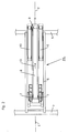
- a horizontal conveyor 10 On both sides of the a horizontal conveyor 10 is provided at an angle, these horizontal conveyors 10 also expediently as conveyor belts are trained. These horizontal conveyors 10 have drive motors with switchable direction of rotation so that the conveyor belts can be moved in two directions are. In addition, these two horizontal conveyors 10 are in their Axial direction shiftable (arrow 12 - Fig. 3). In Fig. 1 are on both sides of the inclined conveyor horizontal conveyor 10 in its two end positions drawn. These horizontal conveyors 10 are located below the discharge edge 9 of the inclined conveyor belt 8 and also parallel to the transport direction (Arrow 13) of the extraction device 22 containing the vertical plane E.
- Arrow 13 transport direction
- these two axes 17 arranged horizontally and are parallel to the transport direction (arrow 13) of the mining device 22 containing the vertical plane E.
- the two horizontal conveyors 10 can either be moved synchronously in the direction of arrow 12 be or in such a way that each horizontal conveyor 10 independently from the other and possibly in opposite sides is.
- the device described above allows two ways of working: one Operation is shown in Fig. 4.
- the two boundary walls 16 of the Bulk channels 14 are against each other to form the gable roof-like guide device 15 pivoted, its ridge edge 18 is in the direction of transport Mining device 22 containing middle vertical plane E. That of the digging and Conveyor wheels 7 picked up and carried up by the inclined conveyor 8 falls over the discharge edge 9 into the V-shaped pouring channel 14 and is here the guide device 15 is divided, and the two material flows thus obtained are noticeable the laterally arranged horizontal conveyors 10, which now take care of the discharge, the respective conversion distance from the position of these horizontal conveyors 10 opposite the discharge edge 9 and its respective direction of rotation depends.
- the mining device moves to convert the old rent 20 to the new rent 21 22 not only in the longitudinal direction of the composting field 3, but also transversely to this (arrow 11 in Fig. 1).
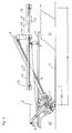
- the removal device 22 has pairs arranged digging and conveyor wheels 7, as they belong to the prior art. It is within the scope of the invention, here also other digging and conveying devices to provide, for example, those in the vertical central plane of the Inclined conveyor 8 are arranged so that the material to be rearranged is not the side is applied to the feeder 8, but from the back Front side is charged.
- the feeder here as a conveyor belt 8 is formed, can also have different configurations, wherein All the means that enable the pourable to be poured in must be included here and pick up goods to be rearranged and transport them upwards, so to achieve a shift.
- the transfer is done without lateral displacement of the goods, since the lying on both sides of the feeder 8 Horizontal conveyor 10 each with the digging and conveyor wheels 7 in or are close to the same vertical plane.
- the axes are 17, around which the boundary walls 16 are pivotable, provided on the lower part of the pouring channel 14.
- the ridge edge 18 of the guide device 15 it would be possible to have the ridge edge 18 of the guide device 15 at the same time as a swivel axis. To be able to work in the way 5, these two boundary walls 16 would then have to be folded together, then the collapsed within the drop area Boundary walls 16 are, however, not significant and noteworthy Show cross-sectional narrowing.
Landscapes
- Chemical & Material Sciences (AREA)
- Health & Medical Sciences (AREA)
- Life Sciences & Earth Sciences (AREA)
- Engineering & Computer Science (AREA)
- Biochemistry (AREA)
- Biotechnology (AREA)
- Chemical Kinetics & Catalysis (AREA)
- General Chemical & Material Sciences (AREA)
- Microbiology (AREA)
- Molecular Biology (AREA)
- Organic Chemistry (AREA)
- Fertilizers (AREA)
Abstract
Description
- Fig. 1
- eine Draufsicht auf ein Kompostierfeld mit einer Abbauvorrichtung;
- Fig. 2
- die Draufsicht auf die Abbauvorrichtung in einem gegenüber Fig. 1 vergrößerten Maßstab und
- Fig. 3
- die Abbauvorrichtung in Seitensicht;
- die Fig. 4 und 5
- die Stirnansicht der Abbauvorrichtung - Blickrichtung Pfeil A in Fig. 3 mit jeweils unterschiedlicher Stellung der Leitvorrichtung.
- 1
- Längsseite
- 2
- Längsseite
- 3
- Kompostierfeld
- 4
- Kranbahn
- 5
- Kranbrücke
- 6
- Laufwagen
- 7
- Grab- und Förderrad
- 8
- Schrägförderer - Förderband
- 9
- Abwurfkante
- 10
- Horizontalförderer
- 11
- Pfeil
- 12
- Pfeil
- 13
- Pfeil
- 14
- Schüttkanal
- 15
- Leitvorrichtung
- 16
- Begrenzungswand
- 17
- Achse
- 18
- Firstkante
- 19
- Pfeil
- 20
- Altmiete
- 21
- Neumiete
- 22
- Abbauvorrichtung
Claims (9)
- Einrichtung zum Umsetzen von auf einem Kompostierfeld (3) gelagertem, verrottbarem Gut zur Kompostierung mit einer längs und quer zum Kompostierfeld (3) verfahrbaren, das umzusetzende Gut aufnehmenden und zumindest in Längsrichtung des Kompostierfeldes (3) transportierenden Abbauvorrichtung (22) mit einer Abwurfkante (9), wobei im Bereich dieser Abwurfkante (9) und unterhalb derselben mindestens zwei parallel zu einer die Transportrichtung der Abbauvorrichtung (22) enthaltenden Vertikalebene angeordnete Horizontalförderer (10), insbesondere Förderbänder vorgesehen sind, die in Richtung ihrer Längsachse verschiebbar gelagert sind, dadurch gekennzeichnet, daß die beiden Horizontalförderer (10) mit Abstand nebeneinander angeordnet sind und zwischen diesen beiden Horizontalförderern (10) die Abwurfkante (9) liegt und unterhalb der Abwurfkante (9) eine satteldachartige Leitvorrichtung (15) angeordnet ist, durch die das über die Abwurfkante (9) abfallende Gut teil- und den Horizontalförderern (10) zuleitbar ist.
- Einrichtung nach Anspruch 1, dadurch gekennzeichnet, daß die Firstkante (18) der satteldachartigen Leitvorrichtung (15) in der die Transportrichtung der Abbauvorrichtung (22) enthaltenden mittleren Vertikalebene (E) liegt.
- Einrichtung nach Anspruch 1 oder 2, dadurch gekennzeichnet, daß die satteldachartige Leitvorrichtung (15) Teil eines V-förmigen Schüttkanales (14) ist und Begrenzungswände (16) desselben bildet.
- Einrichtung nach Anspruch 3, dadurch gekennzeichnet, daß die beiden die satteldachartige Leitvorrichtung (15) bildenden Begrenzungswände (16) des Schüttkanales (14) um zu der die Transportrichtung der Abbauvorrichtung (22) enthaltenden Vertikalebene (E) parallele und im wesentlichen horizontale Achsen (17) schwenkbar sind und diese Achsen (17) an den der Firstkante (18) abgewandten Seite der V-förmigen Leitvorrichtung (15) liegen.
- Einrichtung nach Anspruch 4, dadurch gekennzeichnet, daß der horizontale Abstand der Achsen (17) mindestens so groß ist wie die Breite (W) der Abwurfkante (9).
- Einrichtung nach Anspruch 1, dadurch gekennzeichnet, daß die beiden längsverschiebbaren Horizontalförderer (10) hinsichtlich ihrer Förderrichtung reversibel sind.
- Einrichtung nach Anspruch 1 und 6, dadurch gekennzeichnet, daß die beiden längsverschiebbaren Horizontalförderer (10) synchron in ihrer Längsrichtung verschiebbar sind.
- Einrichtung nach Anspruch 1 und 6, dadurch gekennzeichnet, daß die beiden Horizontalförderer (10) unabhängig voneinander und gegebenenfalls in unterschiedlichen Richtungen längsverschiebbar sind.
- Einrichtung nach Anspruch 1, dadurch gekennzeichnet, daß die Horizontalförderer (10) an einem die Abbauvorrichtung (22) tragenden Laufwagen (6) gelagert sind, der seinerseits entlang einer das Kompostierfeld (3) überspannenden Kranbrücke (5) verfahrbar ist.
Applications Claiming Priority (3)
| Application Number | Priority Date | Filing Date | Title |
|---|---|---|---|
| AT27597 | 1997-02-19 | ||
| AT275/97 | 1997-02-19 | ||
| AT0027597A AT405282B (de) | 1997-02-19 | 1997-02-19 | Einrichtung zum umsetzen von auf einem kompostierfeld gelagertem, verrottbarem gut |
Publications (3)
| Publication Number | Publication Date |
|---|---|
| EP0860409A2 true EP0860409A2 (de) | 1998-08-26 |
| EP0860409A3 EP0860409A3 (de) | 1999-06-16 |
| EP0860409B1 EP0860409B1 (de) | 2001-06-27 |
Family
ID=3486225
Family Applications (1)
| Application Number | Title | Priority Date | Filing Date |
|---|---|---|---|
| EP19980101732 Expired - Lifetime EP0860409B1 (de) | 1997-02-19 | 1998-01-30 | Einrichtung zum Umsetzen von auf einem Kompostierfeld gelagertem, verrottbarem Gut |
Country Status (3)
| Country | Link |
|---|---|
| EP (1) | EP0860409B1 (de) |
| AT (1) | AT405282B (de) |
| DE (1) | DE59800903D1 (de) |
Families Citing this family (1)
| Publication number | Priority date | Publication date | Assignee | Title |
|---|---|---|---|---|
| AT410544B (de) * | 1998-04-09 | 2003-05-26 | Vkw Vogel & Mueller Gmbh | Einrichtung zum umsetzen von auf einem kompostierfeld gelagertem, verrottbarem gut |
Family Cites Families (6)
| Publication number | Priority date | Publication date | Assignee | Title |
|---|---|---|---|---|
| AT386821B (de) * | 1985-06-14 | 1988-10-25 | Vogel Werner Ing | Einrichtung zum umsetzen von muell auf einem kompostierfeld |
| ES2027614T3 (es) * | 1989-03-28 | 1994-01-01 | Buehler Ag Geb | Instalacion de residuos fermentados para la produccion de compost de diferentes grados de madurez. |
| DE4401360A1 (de) * | 1994-01-14 | 1995-07-20 | Sutco Maschinenbau Gmbh | Verfahren und Anordnung zur Umsetzung von Rottematerialien |
| KR0184018B1 (ko) * | 1994-02-03 | 1999-04-01 | 김백기 | 분뇨 호기발효촉진장치 및 발효시스템 그리고 이것을 이용한 퇴비 |
| DE19508616C1 (de) * | 1995-03-10 | 1995-11-09 | Noell Abfall & Energietech | Kompostieranlage zur mechanisch-biologischen Restabfall- und Biomüllbehandlung |
| DE19510225C1 (de) * | 1995-03-23 | 1996-01-04 | Noell Abfall & Energietech | Vorrichtung zum Umsetzen von insbesondere Kompostmieten |
-
1997
- 1997-02-19 AT AT0027597A patent/AT405282B/de not_active IP Right Cessation
-
1998
- 1998-01-30 EP EP19980101732 patent/EP0860409B1/de not_active Expired - Lifetime
- 1998-01-30 DE DE59800903T patent/DE59800903D1/de not_active Expired - Fee Related
Also Published As
| Publication number | Publication date |
|---|---|
| ATA27597A (de) | 1998-11-15 |
| AT405282B (de) | 1999-06-25 |
| DE59800903D1 (de) | 2001-08-02 |
| EP0860409B1 (de) | 2001-06-27 |
| EP0860409A3 (de) | 1999-06-16 |
Similar Documents
| Publication | Publication Date | Title |
|---|---|---|
| DE2152266A1 (de) | Fahrbare Einrichtung zum Aufnehmen bzw.Abtransport von gebrauchten Schienenbefestigungsorganen | |
| EP0367085A2 (de) | Verfahren und Vorrichtung zum Fördern von Rechengut | |
| EP1063184A1 (de) | Anordnung zum Zwischenlagern von Paketen | |
| EP0860409B1 (de) | Einrichtung zum Umsetzen von auf einem Kompostierfeld gelagertem, verrottbarem Gut | |
| DE69703515T2 (de) | Speicher für Einrichtungen zum Schopfen von Metallstäben | |
| EP0059840A2 (de) | Vorrichtung zum Stapeln und Verpacken flacher Gegenstände | |
| CH689670A5 (de) | Foerderanlage mit einer das seitliche Herabfallen von Stueckguetern verhindernden Seitenfuehrung. | |
| DE3540038A1 (de) | Geruest zum beladen von schiffen | |
| DE2626536A1 (de) | Einrichtung zum aufbauen und abbauen von schuettguthalden oder -haufen | |
| EP0010548B1 (de) | In einer Horizontalebene dreh- und arretierbare Umlenkvorrichtung | |
| AT402196B (de) | Einrichtung zum stapeln von plattenförmigen formatzuschnitten und zum abtransport des aus den formatzuschnitten gebildeten stapels | |
| DE2364391C3 (de) | Speicher | |
| EP0860408B1 (de) | Einrichtung zum Umsetzen von auf einem Kompostierfeld gelagertem, verrottbarem Gut | |
| DE8427240U1 (de) | Vorrichtung zum Umformen eines angeförderten breiten Flaschenstroms zu einem abzufördernden einspurigen Flaschenstrom | |
| AT410544B (de) | Einrichtung zum umsetzen von auf einem kompostierfeld gelagertem, verrottbarem gut | |
| AT405508B (de) | Sortier- und stapeleinrichtung für plattenaufteilanlagen | |
| DE2558686C3 (de) | Vorrichtung zum Auflösen von Stückgutlagen in Stückgutzeilen | |
| DE3524778C1 (de) | Vorrichtung zum Aufnehmen und Abfoerdern von in Haufwerken gelagerten Feldfruechten | |
| DE3603212C2 (de) | ||
| DE3331359A1 (de) | Schaufelrad-brueckengeraet | |
| DE2631508A1 (de) | Endloser kettenfoerderer | |
| DE3624731A1 (de) | Wanderndes streckenausbaugestell | |
| DE2929234A1 (de) | Maschine zum be- und entladen von paletten | |
| DE2949493A1 (de) | Geraet zum kontinuirlichen abtragen von schuettguthalden | |
| WO1989003797A1 (fr) | Procede et installation pour l'analyse et l'homogeneisation de produits en vrac |
Legal Events
| Date | Code | Title | Description |
|---|---|---|---|
| PUAI | Public reference made under article 153(3) epc to a published international application that has entered the european phase |
Free format text: ORIGINAL CODE: 0009012 |
|
| AK | Designated contracting states |
Kind code of ref document: A2 Designated state(s): DE ES FR GB IT |
|
| AX | Request for extension of the european patent |
Free format text: AL;LT;LV;MK;RO;SI |
|
| PUAL | Search report despatched |
Free format text: ORIGINAL CODE: 0009013 |
|
| RAP1 | Party data changed (applicant data changed or rights of an application transferred) |
Owner name: VKW-VOGEL & MUELLER GMBH |
|
| RIN1 | Information on inventor provided before grant (corrected) |
Inventor name: VKW-VOGEL & MUELLER GMBH |
|
| AK | Designated contracting states |
Kind code of ref document: A3 Designated state(s): AT BE CH DE DK ES FI FR GB GR IE IT LI LU MC NL PT SE |
|
| AX | Request for extension of the european patent |
Free format text: AL;LT;LV;MK;RO;SI |
|
| RIC1 | Information provided on ipc code assigned before grant |
Free format text: 6C 05F 17/02 A, 6B 65G 65/20 B |
|
| 17P | Request for examination filed |
Effective date: 19991126 |
|
| AKX | Designation fees paid |
Free format text: DE ES FR GB IT |
|
| GRAG | Despatch of communication of intention to grant |
Free format text: ORIGINAL CODE: EPIDOS AGRA |
|
| 17Q | First examination report despatched |
Effective date: 20000522 |
|
| GRAG | Despatch of communication of intention to grant |
Free format text: ORIGINAL CODE: EPIDOS AGRA |
|
| GRAG | Despatch of communication of intention to grant |
Free format text: ORIGINAL CODE: EPIDOS AGRA |
|
| GRAH | Despatch of communication of intention to grant a patent |
Free format text: ORIGINAL CODE: EPIDOS IGRA |
|
| GRAH | Despatch of communication of intention to grant a patent |
Free format text: ORIGINAL CODE: EPIDOS IGRA |
|
| GRAA | (expected) grant |
Free format text: ORIGINAL CODE: 0009210 |
|
| AK | Designated contracting states |
Kind code of ref document: B1 Designated state(s): DE ES FR GB IT |
|
| PG25 | Lapsed in a contracting state [announced via postgrant information from national office to epo] |
Ref country code: IT Free format text: LAPSE BECAUSE OF FAILURE TO SUBMIT A TRANSLATION OF THE DESCRIPTION OR TO PAY THE FEE WITHIN THE PRE;WARNING: LAPSES OF ITALIAN PATENTS WITH EFFECTIVE DATE BEFORE 2007 MAY HAVE OCCURRED AT ANY TIME BEFORE 2007. THE CORRECT EFFECTIVE DATE MAY BE DIFFERENT FROM THE ONE RECORDED.SCRIBED TIME-LIMIT Effective date: 20010627 |
|
| RAP2 | Party data changed (patent owner data changed or rights of a patent transferred) |
Owner name: VKW ANLAGENBAU UND UMWELTTECHNIK GMBH |
|
| RIN2 | Information on inventor provided after grant (corrected) |
Free format text: VKW ANLAGENBAU UND UMWELTTECHNIK GMBH |
|
| REF | Corresponds to: |
Ref document number: 59800903 Country of ref document: DE Date of ref document: 20010802 |
|
| GBT | Gb: translation of ep patent filed (gb section 77(6)(a)/1977) |
Effective date: 20011002 |
|
| ET | Fr: translation filed | ||
| PG25 | Lapsed in a contracting state [announced via postgrant information from national office to epo] |
Ref country code: ES Free format text: LAPSE BECAUSE OF FAILURE TO SUBMIT A TRANSLATION OF THE DESCRIPTION OR TO PAY THE FEE WITHIN THE PRESCRIBED TIME-LIMIT Effective date: 20011220 |
|
| REG | Reference to a national code |
Ref country code: GB Ref legal event code: IF02 |
|
| PGFP | Annual fee paid to national office [announced via postgrant information from national office to epo] |
Ref country code: GB Payment date: 20020130 Year of fee payment: 5 Ref country code: FR Payment date: 20020130 Year of fee payment: 5 |
|
| PGFP | Annual fee paid to national office [announced via postgrant information from national office to epo] |
Ref country code: DE Payment date: 20020320 Year of fee payment: 5 |
|
| PLBE | No opposition filed within time limit |
Free format text: ORIGINAL CODE: 0009261 |
|
| STAA | Information on the status of an ep patent application or granted ep patent |
Free format text: STATUS: NO OPPOSITION FILED WITHIN TIME LIMIT |
|
| 26N | No opposition filed | ||
| PG25 | Lapsed in a contracting state [announced via postgrant information from national office to epo] |
Ref country code: GB Free format text: LAPSE BECAUSE OF NON-PAYMENT OF DUE FEES Effective date: 20030130 |
|
| PG25 | Lapsed in a contracting state [announced via postgrant information from national office to epo] |
Ref country code: DE Free format text: LAPSE BECAUSE OF NON-PAYMENT OF DUE FEES Effective date: 20030801 |
|
| GBPC | Gb: european patent ceased through non-payment of renewal fee | ||
| PG25 | Lapsed in a contracting state [announced via postgrant information from national office to epo] |
Ref country code: FR Free format text: LAPSE BECAUSE OF NON-PAYMENT OF DUE FEES Effective date: 20030930 |
|
| REG | Reference to a national code |
Ref country code: FR Ref legal event code: ST |