EP0859681B1 - Vorrichtung zur applikation von verbindungsmaterialdepots - Google Patents
Vorrichtung zur applikation von verbindungsmaterialdepots Download PDFInfo
- Publication number
- EP0859681B1 EP0859681B1 EP96945850A EP96945850A EP0859681B1 EP 0859681 B1 EP0859681 B1 EP 0859681B1 EP 96945850 A EP96945850 A EP 96945850A EP 96945850 A EP96945850 A EP 96945850A EP 0859681 B1 EP0859681 B1 EP 0859681B1
- Authority
- EP
- European Patent Office
- Prior art keywords
- application
- joining material
- singling
- capillary
- depot
- Prior art date
- Legal status (The legal status is an assumption and is not a legal conclusion. Google has not performed a legal analysis and makes no representation as to the accuracy of the status listed.)
- Expired - Lifetime
Links
Images

Classifications
-
- B—PERFORMING OPERATIONS; TRANSPORTING
- B23—MACHINE TOOLS; METAL-WORKING NOT OTHERWISE PROVIDED FOR
- B23K—SOLDERING OR UNSOLDERING; WELDING; CLADDING OR PLATING BY SOLDERING OR WELDING; CUTTING BY APPLYING HEAT LOCALLY, e.g. FLAME CUTTING; WORKING BY LASER BEAM
- B23K3/00—Tools, devices or special appurtenances for soldering, e.g. brazing, or unsoldering, not specially adapted for particular methods
- B23K3/06—Solder feeding devices; Solder melting pans
- B23K3/0607—Solder feeding devices
- B23K3/0623—Solder feeding devices for shaped solder piece feeding, e.g. preforms, bumps, balls, pellets, droplets
-
- B—PERFORMING OPERATIONS; TRANSPORTING
- B23—MACHINE TOOLS; METAL-WORKING NOT OTHERWISE PROVIDED FOR
- B23K—SOLDERING OR UNSOLDERING; WELDING; CLADDING OR PLATING BY SOLDERING OR WELDING; CUTTING BY APPLYING HEAT LOCALLY, e.g. FLAME CUTTING; WORKING BY LASER BEAM
- B23K3/00—Tools, devices or special appurtenances for soldering, e.g. brazing, or unsoldering, not specially adapted for particular methods
- B23K3/06—Solder feeding devices; Solder melting pans
- B23K3/0607—Solder feeding devices
Definitions
- the present invention relates to a device for separating Application of connection material depots, in particular Solder balls, from a connection material reservoir with a Application device and a separating device for separating connecting material depots from the connecting material reservoir.
- connection material depots With the singular, also under the term “single-point" process known application of connection material depots, So far, the separation has been carried out in a connecting material reservoir connection material depots an isolated recording of the connection material depot by means of the application device, in the manner of a pick-and-place device is operated. For this it is necessary lead the application device to the material reservoir, there you can find a connection material depot and this then transfer to the junction and there place. Because of the short description of the known method it is clear that the application of an isolated connection material depot on a connection point essentially the time required for the Separation of the connection material depots necessary delivery movements the application device is conditional. Out obvious reasons is the well-known, time-consuming Application procedure for the application of isolated connection material depots not for a commercial or even industrial Commitment.
- DE-A-4 320 055 describes a device for separating Application of solder balls from a connection material reservoir with an application device and one as a conveyor trained separation device known, the to promote from the connector material reservoir isolated solder balls to the application device.
- the conveyor is as Gravity conveyor designed.
- soldering gun which for Order from a connecting material reservoir Solder balls used in the liquefied state. This device too is to promote the out of the connector material reservoir individual solder balls to the application device with a gravity conveyor.
- the present invention has for its object a Propose device that will carry out a continuous and precise application of individual Connection material depots enabled.
- the separation device formed as a circular conveyor, so that an arrangement of the transport shots with regular division is possible, the clocked operation of the application device enables.
- the separating device has according to the size of the connection material depots to be separated trained transport recordings on, from a recording position to the individual recording of Connection material depots from the connection material reservoir in a delivery position for delivering the connection material depots are movable to the application device.
- the application device Connection material depots with a defined distance from each other feed so that even at a greater distance between the Connection material reservoir and the application device the time to hand over a connection material depot the application device on the time to overcome the Distance between two transport shots reduced.
- the separating device and the application device are combined in one structural unit operate the device not only stationary, whereby then the one with the connection material depot application connecting points on the application device be moved past, but also one or Train multiaxially movable, so that the device according to Art a bondhead relative to that on substrates or the like provided connection points can be moved.
- the separating device is in a particularly advantageous embodiment designed as a disc conveyor with a driven clocked according to the transport recording division Conveyor disc. This allows the above described advantageous effects of the device in particular realize simple constructive way.
- connection material depot at a connection point is one that can be realized with the simplest of means Handover and placement of the connection material depot to or allows on the junction, in the simplest Execution can only be done by gravity.
- connection material depot there is also the possibility of support the transfer of the respective connection material depot in the application capillary or at the connection point a gas pressurizing device acting on the connection material depot to provide.
- the gas used is a protective gas
- the gas can not only be used to pressurize the material depot, but also to create one inert atmosphere when performing a thermal connection between the connection material depot and the connection point to serve.
- a sensor for detection of connection material is arranged, can be safely determined whether an application is actually to the application device transferred material depot is.
- the application device with a power device to generate the for a connection of a connection material depot necessary energy connected to the connection point which is dependent on that by the gas pressurizing device caused gas pressure can be used to transfer the material depot to the application device supporting gas pressure at the same time can also be used to trigger the energy device.
- a separate triggering device becomes superfluous. Secondly, it ensures that a trip the energy device actually only takes place if as a result of the connection material depot acting as a pressure resistor a static overpressure in the application capillary is built up. The trigger is actually only when a connection material depot for application on the Connection point is available. False triggering of the Energy devices are therefore excluded.
- the type of Triggering of the energy device is particularly advantageous for Triggering a single or a series of laser pulses use.
- the use of a laser source proves to be an energy device as particularly advantageous, since this is particularly simple way of generating energy necessary devices arranged separately from the device can be and only one the mobility of the device non-restrictive connection to the laser source via the optical fiber is necessary.
- laser exposure has the advantage that none relative to the other devices of the device movable elements are necessary. This will total a particularly simple construction of the device possible.
- connection material depot When transferring a connection material depot from the Dispensing position in the application capillary at an angle is provided, it is possible to the final cross section of the optical fiber at the separating device passed in the area of the mouthpiece of the Application capillary to arrange one in the application capillary arranged and on the relevant junction if possible small focusing distance between the optical fiber cross section and to have the connection material depot.
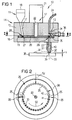
- FIG. 1 shows a depot applicator 10 with a connection material reservoir 11, a separating device 12 and an application device 13.
- the connecting material reservoir 11, the separating device 12 and the applicator device 13 are combined to form a structural unit and are arranged in or on a common housing 14.
- the housing 14 has an upper housing part 15 and a lower housing part 16.
- the connecting material reservoir 11 consists of a rising channel 17 formed in the upper housing part 15 and a storage funnel 18 which opens into the rising channel 17 and is mounted on the upper housing part 15.
- the rising channel 17 opens into a receiving space 19 formed in the lower housing part 16 for receiving a conveyor disk 20, which together with a Drive motor 21 forms the separating device 12.
- the conveyor disk 20 is connected via a drive shaft 22 which runs through the upper housing part 15 to the drive motor 21 which is flanged onto the upper side of the upper housing part 15.
- the application device 13 Opposite the connecting material reservoir 11 and also how this is arranged in the peripheral region of the conveyor disc 20 is the application device 13, the one Application capillary 23 and one here as an optical fiber 24 trained energy application device that Part of a laser device not shown in detail here is.
- the conveyor disk 20 has a plurality of transport receptacles 25 arranged in a uniform division on a receiving pitch circle 26.
- the conveyor disk 20 is driven counterclockwise in the present case by the drive motor 21.
- the drive is clocked in steps, so that when the conveyor disk 20 is at a standstill, a transport receptacle 25 is in overlap with an output opening 27 of the riser channel 17 and in overlap with the application capillary 23 of the application device 13.
- the overlap position of a transport receptacle 25 with the discharge opening 27 of the riser 17 is referred to as the receptacle position 28 and the overlap position of a transport receptacle 25 with the application capillary 23 as the dispensing position 29.
- connecting material depots 30 which have been arranged in a disorderly manner in the connecting material reservoir 11 are individually picked up by the conveyor disk 20 in the receiving position 28 by being received in the transport receptacles 25.
- the connection depots 30 accommodated in the conveyor disk 20 in this way are advanced in the direction of the application device 13 and transferred to the delivery device 29 in the delivery position 29. 2 makes it clear that to the extent that the connection material depots 30 are transferred to the conveyor disk 20 in the receiving position 28, the connection material depots 30 are transferred to the application device 13 in the delivery position 29 as a result of the rotary movement (arrow 50) of the conveyor disk 20. Therefore, during a continuous operation of the separating device 12, the stationary filling of the conveyor disk 20 shown in FIG. 2 is reached over half the receiving pitch circle 26.
- FIG. 1 shows that the application capillary 23 of the application device 13 is provided with a capillary mouthpiece 31, which is used to place a connection material depot 30 shown in FIG. 1 with a dashed line in an application position 32.
- the optical fiber 24 is introduced into the end region of the application capillary 23 opposite the capillary mouthpiece 31 in such a way that it is arranged coaxially with the application capillary 23 and essentially aligned with respect to an exit beam direction 33.
- the optical fiber 24 with its laser radiation-emitting end cross section 34 is arranged above the conveyor disk 20. There is a capillary space 35 between the conveyor disk 20 and the end cross section 34, into which a compressed gas connection 36 opens.
- the pressurized gas connection 36 serves to pressurize the capillary free space 35 with increased pressure, so that the connection material depot 30 arranged in the dispensing position 29 is driven out of the transport receptacle 25 designed as a through hole and is transferred to the application position 32 shown in FIG. 1 with a dashed line.
- the connection material depot 30 rests on a connection surface 37 of a substrate, which is approximately a chip 38.
- connection material depot 30 there is a gap s between an end cross-section 39 of the capillary mouthpiece 31 and the surface of the connecting surface 37, which is dimensioned such that on the one hand the connection material depot 30 is held securely in the application position 32 shown, and on the other hand is sufficient to prevent an essentially unhindered thermal deformation of the connection material depot 30 to form an elevated contact metallization, not shown in more detail, known technically under the term "bump".
- the depot applicator 10 or the depot applicator 43 can be used to produce bumps as are required to carry out “flip-chip” contacts.
- the pressurized gas supply to the connection material depot 30 also serves to trigger the laser device.
- a pressure sensor 40 is provided in the capillary mouthpiece 31, which detects a static excess pressure in the application capillary 23. Since a static excess pressure builds up in the application capillary 23 only when the gap s is essentially closed by the connection material depot 30 arranged in the application position 32, the laser device is also only triggered when a connection material depot 30 is placed on the connection surface 37 . Before placement, the capillary mouthpiece can optionally be moved in the vertical direction.
- connection material depot 30 Influencing the laser radiation emitted from the optical fiber 24 capture. This can be the reflection of the radiation or perhaps one caused by the connection material depot 30 Wavelength change in radiation can be detected.
- connection point here the connection surface 37
- connection surface 37 can transmit laser radiation by means of the optical fiber 24 suitable wavelength and pulsation on the connection point be judged.
- sensors 41 and 42 for the detection of connecting material by one division on the receiving pitch circle 26 from the dispensing position 29.
- the sensor 41 is in the direction of rotation (arrow 50) of the conveyor disk 20 in front of the delivery position 29 and the sensor 42 behind the delivery position 29. Both sensors 41, 42 are arranged in the lower housing part 16 directly opposite the receiving pitch circle 26.
- the sensor 41 thus makes it possible to determine whether a transport receptacle 25 for the subsequent transfer of a connection material depot 30 to the application capillary is filled in the dispensing position 29.
- the sensor 42 checks whether the connection material depot 30 has actually been transferred to the application capillary.
- the sensors 41, 42 are used to determine malfunctions, so that in the event that an unfilled transport receptacle 25 is detected by the sensor 41, the conveyor disk 20 can be clocked further by one division. The same applies if the sensor 42 detects a connection material depot 30 in the transport receptacle 25 after the delivery position 29 has been exceeded.
- FIG. 3 shows a depot applicator 43 which is largely of the same design as the depot applicator 10 shown in FIG. 1 and , like the depot applicator 10, contains a conveyor disk 20 which is arranged in a receiving space 19 between an upper housing part 44 and a lower housing part 45.
- adjacent surfaces of the upper housing part 44 and the lower housing part 45 form boundary surfaces for the connecting material depots 30 accommodated in transport receptacles 25 designed as through bores, so that these are conveyed in the conveyor disk 20 from the receiving position 28 to the position in which they are conveyed Delivery position 29 are secured against falling out.
- a gap not shown in detail in FIGS. 1 and 3 , is provided in each case between the opposite surfaces of the conveyor disk 20 and the upper housing part 15 or the lower housing part 16.
- a flange-like housing collar 51 on the lower housing part 16 or 45 essentially serves to set this gap.
- Fig. 4 shows an enlarged view of the reception of a connection material depot 30 from the connection material reservoir 11 by the conveyor disk 20 in the receiving position 28.
- the connection material depots 30 arranged closely together in the riser channel 17 of the connection material reservoir 11 are under the influence of gravity into the overlap with the outlet opening 27 of the Transfer channel 25 arranged transport receptacle 25.
- the conveyor disk 20 or a part of the connecting material reservoir 11 can be subjected to ultrasound, so that if the connecting material depot 30 is positioned in an unfavorable relative manner in the riser channel 17, the filling of the transport receptacle 25 can be prevented from jamming the connecting material depot 30.
- Such an ultrasound exposure is also possible by directly loading the connection material depots 30, for example by means of an ultrasound probe extending into the riser channel 17.
- the depot applicator 43 has a modified application device 46, in which the connection material depots 30 are not transferred directly from the dispensing position 29 into an application capillary 47, but instead, starting from the dispensing position 29, first into one Feed capillary 48 which runs obliquely downwards and opens into the application capillary 47.
- this ensures that the application capillary 47 with the optical fiber 24 flowing into it can be guided past the conveyor disk 20 laterally.
- the result of this is that the end cross section 34 of the optical fiber 24 can be brought closer to the end cross section 39 of the capillary mouthpiece 31, so that a shorter distance between the end cross section 34 and the connecting material depot 30 arranged in the application position 32 on the connection surface 37 ( FIG. 1 ) is adjustable. This enables a greater melting capacity when remelting the connecting material depot 30 by means of laser energy.
- the depicted embodiments of the depot applicator serve for application of lumpy, here spherical Connection material depots 30, for example solder balls.
- the depot applicator is not independent of the embodiment on the use of solid or lumpy connection material depots limited. Rather, the use is more fluid or viscous connection material depots possible, whereby then expediently when transferring from the connecting material reservoir portioning to the separating device he follows.
- This cleaning device can be designed similarly to the application device 13 or 46 with a pressurized gas connection for blowing out transport receptacles 25 that are not completely emptied, and optionally also an optical fiber, which enables the transport receptacles 25 to be "burned free” by laser exposure of the transport receptacles 25.
Landscapes
- Engineering & Computer Science (AREA)
- Mechanical Engineering (AREA)
- Coating Apparatus (AREA)
- Electric Connection Of Electric Components To Printed Circuits (AREA)
- Application Of Or Painting With Fluid Materials (AREA)
- Coupling Device And Connection With Printed Circuit (AREA)
- Connections By Means Of Piercing Elements, Nuts, Or Screws (AREA)
- Manufacturing Of Electrical Connectors (AREA)
- Lining Or Joining Of Plastics Or The Like (AREA)
- Wire Bonding (AREA)
Description
- Fig. 1
- einen teilweise im Schnitt dargestellten Depotapplikator in einer ersten Ausführungsform;
- Fig. 2
- eine Schnittdarstellung des in Fig. 1 dargestellten Depotapplikators gemäß Schnittlinienverlauf II-II in Fig. 1;
- Fig. 3
- eine teilweise Schnittdarstellung eines Depotapplikators in einer zweiten Ausführungsform;
- Fig. 4
- eine mit X bezeichnete vergrößerte Detaildarstellung des in Fig. 3 dargestellten Depotapplikators.
Claims (12)
- Vorrichtung zur vereinzelten Applikation von Verbindungsmaterialdepots, insbesondere Lotkugeln, aus einem Verbindungsmaterialreservoir mit einer Applikationseinrichtung und einer Vereinzelungseinrichtung zur Vereinzelung von Verbindungsmaterialdepots aus dem Verbindungsmaterialreservoir, wobei die Vereinzelungseinrichtung als Fördereinrichtung zur vereinzelten Übergabe von Verbindungsmaterialdepots an die Applikationseinrichtung ausgebildet ist,
dadurch gekennzeichnet,
daß die Vereinzelungseinrichtung (12) als Kreisfördereinrichtung (20) ausgebildet ist. - Vorrichtung nach Anspruch 1,
dadurch gekennzeichnet,
daß die Vereinzelungseinrichtung (12) entsprechend der Größe der zu vereinzelnden Verbindungsmaterialdepots ausgebildete Transportaufnahmen (25) aufweist, die von einer Aufnahmeposition (28) zur vereinzelten Aufnahme von Verbindungsmaterialdepots (30) aus dem Verbindungsmaterialreservoir (11) in eine Abgabeposition (29) zur Abgabe der Verbindungsmaterialdepots an die Applikationseinrichtung (13; 46) bewegbar sind. - Vorrichtung nach einem der vorangehenden Ansprüche,
dadurch gekennzeichnet,
daß die Vereinzelungseinrichtung (12) und die Applikationseinrichtung (13; 46) zu einer baulichen Einheit zusammengefaßt sind. - Vorrichtung nach einem der vorangehenden Ansprüche,
dadurch gekennzeichnet,
daß das Materialreservoir (11), die Vereinzelungseinrichtung (12) und die Applikationseinrichtung (13; 46) zu einer baulichen Einheit zusammengefaßt sind. - Vorrichtung nach einem der vorangehenden Ansprüche,
dadurch gekennzeichnet,
daß die Vereinzelungseinrichtung (12) als Scheibenförderer (20) ausgebildet ist mit einer entsprechend der Transportaufnahmenteilung (26) getaktet angetriebenen Förderscheibe (20). - Vorrichtung nach einem der vorangehenden Ansprüche,
dadurch gekennzeichnet,
daß die Verbindungsmaterialdepots (30) in ihrer Abgabeposition (29) in eine Applikationskapillare (23) überführt werden, die zur Plazierung des Verbindungsmaterialdepots (30) an einer Verbindungsstelle (37) dient. - Vorrichtung nach Anspruch 6,
dadurch gekennzeichnet,
daß zur Unterstützung der Überführung der jeweiligen Verbindungsmaterialdepots (30) in die Applikationskapillare (23) eine auf das Verbindungsmaterialdepot wirkende Druckgasbeaufschlagungseinrichtung (36) vorgesehen ist. - Vorrichtung nach einem der vorangehenden Ansprüche,
dadurch gekennzeichnet,
daß in Förderrichtung (27) der Vereinzelungseinrichtung (12) vor der Abgabeposition (29) ein Sensor (41) zur Detektierung von Verbindungsmaterial angeordnet ist. - Vorrichtung nach Anspruch 8,
dadurch gekennzeichnet,
daß in Förderrichtung der Vereinzelungseinrichtung (12) hinter der Abgabeposition (29) ein Sensor (42) zur Detektierung von Verbindungsmaterial angeordnet ist. - Vorrichtung nach einem der vorangehenden Ansprüche,
dadurch gekennzeichnet,
daß die Applikationseinrichtung (13; 46) mit einer Energieeinrichtung zur Erzeugung der für eine Verbindung eines Verbindungsmaterialdepots (30) mit der Verbindungsstelle (37) notwendigen Energie verbunden ist, die in Abhängigkeit von dem durch die Druckgasbeaufschlagungseinrichtung (36) bewirkten Gasdruck ausgelöst wird. - Vorrichtung nach einem der vorangehenden Ansprüche,
dadurch gekennzeichnet,
daß die Applikationseinrichtung (13; 46) zur Verbindung mit einer Laserquelle zur Erzeugung der für eine Verbindung eines Verbindungsmaterialdepots (30) mit der Verbindungsstelle (37) notwendigen Energie eine in die Applikationskapillare (23) mündende Lichtleitfaser (24) aufweist. - Vorrichtung nach einem der vorangehenden Ansprüche,
dadurch gekennzeichnet,
daß zur Überführung eines Verbindungsmaterialdepots (30) aus der Abgabeposition (29) in die Applikationskapillare (47) eine schräg nach unten verlaufende Zuführkapillare (48) vorgesehen ist.
Applications Claiming Priority (3)
| Application Number | Priority Date | Filing Date | Title |
|---|---|---|---|
| DE19541996 | 1995-11-10 | ||
| DE19541996A DE19541996C2 (de) | 1995-11-10 | 1995-11-10 | Vorrichtung zur Applikation von Verbindungsmaterialeinheiten |
| PCT/DE1996/002078 WO1997017191A2 (de) | 1995-11-10 | 1996-10-30 | Vorrichtung zur applikation von verbindungsmaterialdepots |
Publications (2)
| Publication Number | Publication Date |
|---|---|
| EP0859681A2 EP0859681A2 (de) | 1998-08-26 |
| EP0859681B1 true EP0859681B1 (de) | 1999-07-14 |
Family
ID=7777172
Family Applications (1)
| Application Number | Title | Priority Date | Filing Date |
|---|---|---|---|
| EP96945850A Expired - Lifetime EP0859681B1 (de) | 1995-11-10 | 1996-10-30 | Vorrichtung zur applikation von verbindungsmaterialdepots |
Country Status (7)
| Country | Link |
|---|---|
| US (1) | US6152348A (de) |
| EP (1) | EP0859681B1 (de) |
| JP (1) | JPH11514933A (de) |
| AT (1) | ATE182099T1 (de) |
| DE (2) | DE19541996C2 (de) |
| ES (1) | ES2134655T3 (de) |
| WO (1) | WO1997017191A2 (de) |
Cited By (4)
| Publication number | Priority date | Publication date | Assignee | Title |
|---|---|---|---|---|
| US6955284B2 (en) | 2000-10-06 | 2005-10-18 | Pac Tec-Packaging Technologies Gmbh | Device for positioning a tool in relation to a workpiece |
| US7971339B2 (en) | 2006-09-26 | 2011-07-05 | Hid Global Gmbh | Method and apparatus for making a radio frequency inlay |
| US8286332B2 (en) | 2006-09-26 | 2012-10-16 | Hid Global Gmbh | Method and apparatus for making a radio frequency inlay |
| US8413316B2 (en) | 2007-09-18 | 2013-04-09 | Hid Global Ireland Teoranta | Method for bonding a wire conductor laid on a substrate |
Families Citing this family (47)
| Publication number | Priority date | Publication date | Assignee | Title |
|---|---|---|---|---|
| DE59807021D1 (de) * | 1997-06-13 | 2003-02-27 | Pac Tech Gmbh | Verfahren und vorrichtung zur reparatur defekter lotverbindungsstellen |
| DE19838532B4 (de) * | 1997-08-28 | 2005-09-22 | Pac Tech - Packaging Technologies Gmbh | Verfahren und Vorrichtung zum Plazieren und Umschmelzen von Lotmaterialformstücken |
| DE19742711C1 (de) * | 1997-09-26 | 1999-05-20 | Intec Bielenberg Gmbh & Co Kg | Vorrichtung zum Aufbringen von Klebepunkten auf ein Substrat |
| US6324973B2 (en) | 1997-11-07 | 2001-12-04 | Speedline Technologies, Inc. | Method and apparatus for dispensing material in a printer |
| US5947022A (en) * | 1997-11-07 | 1999-09-07 | Speedline Technologies, Inc. | Apparatus for dispensing material in a printer |
| US6453810B1 (en) | 1997-11-07 | 2002-09-24 | Speedline Technologies, Inc. | Method and apparatus for dispensing material in a printer |
| JP4068304B2 (ja) | 1998-08-25 | 2008-03-26 | ピーエーシー ティーイーシーエイチ − パッケージング テクノロジーズ ゲゼルシャフト ミット ベシュレンクテル ハフツング | 半田材料製形状部品の配置、再溶融方法およびその装置 |
| US6227437B1 (en) * | 1999-08-24 | 2001-05-08 | Kulicke & Soffa Industries Inc. | Solder ball delivery and reflow apparatus and method of using the same |
| US6386433B1 (en) * | 1999-08-24 | 2002-05-14 | Kulicke & Soffa Investments, Inc. | Solder ball delivery and reflow apparatus and method |
| US6336581B1 (en) * | 2000-06-19 | 2002-01-08 | International Business Machines Corporation | Solder ball connection device and capillary tube thereof |
| WO2002028589A1 (de) * | 2000-10-06 | 2002-04-11 | Pac Tech - Packaging Technologies Gmbh | Verfahren und vorrichtung zur applikation von materialstücken auf ein werkstück |
| EP1330328B1 (de) | 2000-10-06 | 2005-12-28 | Pac Tech - Packaging Technologies GmbH | Verfahren und vorrichtung zur applikation von materialstücken auf ein werkstück |
| DE10132567B4 (de) * | 2001-07-10 | 2005-03-31 | Pac Tech - Packaging Technologies Gmbh | Verfahren und Vorrichtung zum Aufbringen eines Lötmittels auf ein Substrat |
| AU2005304141B2 (en) * | 2004-11-02 | 2010-08-26 | Hid Global Gmbh | Laying device, contacting device, advancing system, laying and contacting unit, production system, method for the production and a transponder unit |
| JP4338204B2 (ja) * | 2005-03-30 | 2009-10-07 | Tdk株式会社 | 半田付け方法及び半田付け装置並びに接合方法及び接合装置 |
| JP4042914B2 (ja) | 2005-04-22 | 2008-02-06 | Tdk株式会社 | 半田付け装置及び半田分配装置 |
| US20070075056A1 (en) * | 2005-09-30 | 2007-04-05 | Sae Magnetics (H.K.) Ltd. | Soldering device and method for forming electrical solder connections in a disk drive unit |
| US8608080B2 (en) * | 2006-09-26 | 2013-12-17 | Feinics Amatech Teoranta | Inlays for security documents |
| US7980477B2 (en) * | 2007-05-17 | 2011-07-19 | Féinics Amatech Teoranta | Dual interface inlays |
| JP5393235B2 (ja) * | 2009-04-23 | 2014-01-22 | パナソニック株式会社 | 半田付け装置及び半田付け方法 |
| JP2011121070A (ja) * | 2009-12-08 | 2011-06-23 | Hitachi Global Storage Technologies Netherlands Bv | ヘッド・ジンバル・アセンブリの製造方法及びヘッド・ジンバル・アセンブリの接続パッドを相互接続する装置 |
| US20130256281A1 (en) * | 2012-03-30 | 2013-10-03 | Tatsumi Tsuchiya | Solder-jet nozzle, laser-soldering tool, and method, for lasersoldering head-connection pads of a head-stack assembly for a hard-disk drive |
| US9227260B2 (en) * | 2013-02-14 | 2016-01-05 | HGST Netherlands B.V. | High-speed transportation mechanism for micro solder balls |
| US9501067B2 (en) | 2013-09-19 | 2016-11-22 | Gpd Global, Inc. | Fluid pressure regulation system for fluid-dispensing systems |
| DE102013017159B3 (de) | 2013-10-16 | 2014-12-24 | Pac Tech - Packaging Technologies Gmbh | Vorrichtung zur vereinzelten Applikation von Lotmaterialdepots |
| DE102013114447B4 (de) | 2013-12-19 | 2016-01-28 | Pac Tech - Packaging Technologies Gmbh | Vorrichtung zur vereinzelten Applikation von Lotmaterialdepots |
| DE102013114453A1 (de) | 2013-12-19 | 2015-06-25 | Pac Tech-Packaging Technologies Gmbh | Vorrichtung zur vereinzelten Applikation von Lotmaterialdepots |
| DE102014109934A1 (de) * | 2014-07-15 | 2016-01-21 | Pac Tech - Packaging Technologies Gmbh | Vorrichtung zur vereinzelten Applikation von Verbindungsmaterialdepots |
| US10556284B2 (en) * | 2015-08-24 | 2020-02-11 | Seagate Technology Llc | Method of forming electrical connections with solder dispensing and reflow |
| JP6453742B2 (ja) * | 2015-11-09 | 2019-01-16 | 株式会社パラット | 半田付け装置、および半田付け方法 |
| US10730128B2 (en) * | 2016-01-20 | 2020-08-04 | Western Digital Technologies, Inc. | Reliable transportation mechanism for micro solder balls |
| WO2018079515A1 (ja) * | 2016-10-28 | 2018-05-03 | 株式会社アンド | 鏝先の状態判定方法 |
| JP6785512B2 (ja) * | 2017-09-27 | 2020-11-18 | 株式会社堀内電機製作所 | はんだ付けシステム |
| US11282357B2 (en) | 2018-05-22 | 2022-03-22 | Tyco Fire & Security Gmbh | Elongate flexible tag |
| JP7286372B2 (ja) * | 2019-03-29 | 2023-06-05 | 株式会社パラット | 半田付け装置、および半田付け装置用ノズル |
| US12223814B2 (en) | 2019-09-16 | 2025-02-11 | Sensormatic Electronics, LLC | Security tag for textiles using conductive thread |
| US10970613B1 (en) | 2019-09-18 | 2021-04-06 | Sensormatic Electronics, LLC | Systems and methods for providing tags adapted to be incorporated with or in items |
| US11443160B2 (en) | 2019-09-18 | 2022-09-13 | Sensormatic Electronics, LLC | Systems and methods for laser tuning and attaching RFID tags to products |
| US11055588B2 (en) | 2019-11-27 | 2021-07-06 | Sensormatic Electronics, LLC | Flexible water-resistant sensor tag |
| US12524640B2 (en) | 2019-11-27 | 2026-01-13 | Sensormatic Electronics, LLC | Flexible water-resistant sensor tag |
| US11247285B1 (en) | 2020-04-03 | 2022-02-15 | Seagate Technology Llc | Fluidization of agglomerated solder microspheres |
| US11755874B2 (en) | 2021-03-03 | 2023-09-12 | Sensormatic Electronics, LLC | Methods and systems for heat applied sensor tag |
| JP7460052B2 (ja) | 2021-10-06 | 2024-04-02 | パック テック-パッケージング テクノロジーズ ゲーエムベーハー | 単一はんだ体を製造するためのプレス成形デバイス、装置、はんだ付着機及び方法 |
| US11869324B2 (en) | 2021-12-23 | 2024-01-09 | Sensormatic Electronics, LLC | Securing a security tag into an article |
| CN114160908B (zh) * | 2022-02-11 | 2022-05-06 | 江苏高凯精密流体技术股份有限公司 | 激光熔锡喷射焊多通道进料系统 |
| US12536401B2 (en) | 2022-08-31 | 2026-01-27 | Sensormatic Electronics, LLC | Security tag |
| CN117840536A (zh) * | 2022-10-04 | 2024-04-09 | 派克泰克封装技术有限公司 | 激光辅助焊接设备 |
Family Cites Families (6)
| Publication number | Priority date | Publication date | Assignee | Title |
|---|---|---|---|---|
| US1673281A (en) * | 1924-08-09 | 1928-06-12 | Western Electric Co | Method of and apparatus for dispensing matter |
| FR2397910A1 (fr) * | 1977-07-19 | 1979-02-16 | Gleizes Raymond | Ensemble automatique et portatif pour le soudage |
| US4936501A (en) * | 1989-04-13 | 1990-06-26 | Sergei Babarin | Soldering device |
| GB2284933B (en) * | 1993-05-31 | 1996-12-04 | Citizen Watch Co Ltd | Solder ball feeder |
| DE4320055A1 (de) * | 1993-06-17 | 1994-12-22 | Ghassem Dipl Ing Azdasht | Belötungsvorrichtung |
| US5828031A (en) * | 1996-06-27 | 1998-10-27 | International Business Machines Corporation | Head transducer to suspension lead termination by solder ball place/reflow |
-
1995
- 1995-11-10 DE DE19541996A patent/DE19541996C2/de not_active Expired - Lifetime
-
1996
- 1996-10-30 AT AT96945850T patent/ATE182099T1/de active
- 1996-10-30 US US09/068,613 patent/US6152348A/en not_active Expired - Lifetime
- 1996-10-30 ES ES96945850T patent/ES2134655T3/es not_active Expired - Lifetime
- 1996-10-30 DE DE59602458T patent/DE59602458D1/de not_active Expired - Lifetime
- 1996-10-30 WO PCT/DE1996/002078 patent/WO1997017191A2/de not_active Ceased
- 1996-10-30 JP JP9517741A patent/JPH11514933A/ja not_active Ceased
- 1996-10-30 EP EP96945850A patent/EP0859681B1/de not_active Expired - Lifetime
Cited By (4)
| Publication number | Priority date | Publication date | Assignee | Title |
|---|---|---|---|---|
| US6955284B2 (en) | 2000-10-06 | 2005-10-18 | Pac Tec-Packaging Technologies Gmbh | Device for positioning a tool in relation to a workpiece |
| US7971339B2 (en) | 2006-09-26 | 2011-07-05 | Hid Global Gmbh | Method and apparatus for making a radio frequency inlay |
| US8286332B2 (en) | 2006-09-26 | 2012-10-16 | Hid Global Gmbh | Method and apparatus for making a radio frequency inlay |
| US8413316B2 (en) | 2007-09-18 | 2013-04-09 | Hid Global Ireland Teoranta | Method for bonding a wire conductor laid on a substrate |
Also Published As
| Publication number | Publication date |
|---|---|
| WO1997017191A3 (de) | 1997-06-26 |
| ATE182099T1 (de) | 1999-07-15 |
| DE59602458D1 (de) | 1999-08-19 |
| DE19541996A1 (de) | 1997-05-15 |
| WO1997017191A2 (de) | 1997-05-15 |
| US6152348A (en) | 2000-11-28 |
| JPH11514933A (ja) | 1999-12-21 |
| EP0859681A2 (de) | 1998-08-26 |
| ES2134655T3 (es) | 1999-10-01 |
| DE19541996C2 (de) | 1997-09-25 |
Similar Documents
| Publication | Publication Date | Title |
|---|---|---|
| DE19541996C2 (de) | Vorrichtung zur Applikation von Verbindungsmaterialeinheiten | |
| DE69706967T2 (de) | Vorrichtung zum wiegen von kleinen gegenständen wie gelatinekapseln | |
| DE68907709T2 (de) | Kapselfüllvorrichtung. | |
| DE69605844T2 (de) | Anordnung zum Verpacken von Gegenständen in Verpackungen | |
| DE3830013C2 (de) | Füll- und Schließmaschine für zweiteilige Kapseln | |
| DE3309205C2 (de) | Vorrichtung zum Transportieren einer Reihe zylindrischer Pellets | |
| EP3169468B1 (de) | Vorrichtung zur vereinzelten applikation von verbindungsmaterialdepots | |
| DE3125237C2 (de) | ||
| DE10132567A1 (de) | Verfahren und Vorrichtung zum Aufbringen eines Lötmittels auf ein Substrat | |
| EP3909872A1 (de) | Verfahren und anordnung zum übergeben von produkten | |
| EP3645180A2 (de) | Behälterreinigungsmaschine mit einem tauchbad und einer spritzstation | |
| EP2248604A1 (de) | Vorrichtung zum Aussortieren von fehlerhaften, zylindrischen Medikamentenkapseln | |
| DE60212794T2 (de) | Vorrichtung zum Sammeln und Wiederverwerten von nach zuführenden Kanälen gerichteten Gegenständen | |
| EP0170670A1 (de) | Transporteinrichtung für tabletten. | |
| DE2015512A1 (de) | Umsetzvorrichtung für Behälter zwischen einem ersten und einem zweiten Förderer | |
| DE19648447A1 (de) | Vorrichtung zur Handhabung von Blisterstreifen | |
| DE102022100828B4 (de) | Vorrichtung für kleinvolumiges Schüttgut | |
| DE19549757B4 (de) | Vorrichtung, bestehend aus einem Füllschacht und einer diesem Produkt zuführenden Produktzuführeinrichtung | |
| DE4332645C2 (de) | Getränkefüllmaschine | |
| DE19838532B4 (de) | Verfahren und Vorrichtung zum Plazieren und Umschmelzen von Lotmaterialformstücken | |
| DE2652653A1 (de) | Verschluss-reinigungs-maschine | |
| DE69015054T2 (de) | Verpackungsmaschine zum Füllen von Röhrchen mit Tabletten oder dgl. | |
| DE4000588C2 (de) | Vorrichtung zum Unterbrechen des Befüllvorgangs an einer Verpackungsmaschine | |
| DE29707734U1 (de) | Vorrichtung zum Prüfen von Hohlkörpern | |
| EP0396038A3 (de) | Kalkdosiervorrichtung sowie Verfahren zu deren Betrieb |
Legal Events
| Date | Code | Title | Description |
|---|---|---|---|
| PUAI | Public reference made under article 153(3) epc to a published international application that has entered the european phase |
Free format text: ORIGINAL CODE: 0009012 |
|
| 17P | Request for examination filed |
Effective date: 19980609 |
|
| AK | Designated contracting states |
Kind code of ref document: A2 Designated state(s): AT CH DE ES FR GB IT LI NL |
|
| GRAG | Despatch of communication of intention to grant |
Free format text: ORIGINAL CODE: EPIDOS AGRA |
|
| 17Q | First examination report despatched |
Effective date: 19981019 |
|
| GRAG | Despatch of communication of intention to grant |
Free format text: ORIGINAL CODE: EPIDOS AGRA |
|
| GRAH | Despatch of communication of intention to grant a patent |
Free format text: ORIGINAL CODE: EPIDOS IGRA |
|
| GRAH | Despatch of communication of intention to grant a patent |
Free format text: ORIGINAL CODE: EPIDOS IGRA |
|
| RAP1 | Party data changed (applicant data changed or rights of an application transferred) |
Owner name: RIETZLER, MANFRED Owner name: FINN, DAVID |
|
| GRAA | (expected) grant |
Free format text: ORIGINAL CODE: 0009210 |
|
| AK | Designated contracting states |
Kind code of ref document: B1 Designated state(s): AT CH DE ES FR GB IT LI NL |
|
| REF | Corresponds to: |
Ref document number: 182099 Country of ref document: AT Date of ref document: 19990715 Kind code of ref document: T |
|
| REG | Reference to a national code |
Ref country code: CH Ref legal event code: EP |
|
| REG | Reference to a national code |
Ref country code: CH Ref legal event code: NV Representative=s name: HEPP, WENGER & RYFFEL AG |
|
| GBT | Gb: translation of ep patent filed (gb section 77(6)(a)/1977) |
Effective date: 19990719 |
|
| REF | Corresponds to: |
Ref document number: 59602458 Country of ref document: DE Date of ref document: 19990819 |
|
| ET | Fr: translation filed | ||
| ITF | It: translation for a ep patent filed | ||
| REG | Reference to a national code |
Ref country code: ES Ref legal event code: FG2A Ref document number: 2134655 Country of ref document: ES Kind code of ref document: T3 |
|
| PLBE | No opposition filed within time limit |
Free format text: ORIGINAL CODE: 0009261 |
|
| STAA | Information on the status of an ep patent application or granted ep patent |
Free format text: STATUS: NO OPPOSITION FILED WITHIN TIME LIMIT |
|
| 26N | No opposition filed | ||
| REG | Reference to a national code |
Ref country code: GB Ref legal event code: IF02 |
|
| PGFP | Annual fee paid to national office [announced via postgrant information from national office to epo] |
Ref country code: NL Payment date: 20021017 Year of fee payment: 7 |
|
| PG25 | Lapsed in a contracting state [announced via postgrant information from national office to epo] |
Ref country code: NL Free format text: LAPSE BECAUSE OF NON-PAYMENT OF DUE FEES Effective date: 20040501 |
|
| NLV4 | Nl: lapsed or anulled due to non-payment of the annual fee |
Effective date: 20040501 |
|
| REG | Reference to a national code |
Ref country code: FR Ref legal event code: TP |
|
| REG | Reference to a national code |
Ref country code: GB Ref legal event code: 732E |
|
| REG | Reference to a national code |
Ref country code: GB Ref legal event code: 732E |
|
| REG | Reference to a national code |
Ref country code: GB Ref legal event code: 732E |
|
| REG | Reference to a national code |
Ref country code: CH Ref legal event code: PUE Owner name: SMARTRAC IP B.V. Free format text: RIETZLER, MANFRED#AM ALSTERBERG 10#87616 MARKTOBERDORF (DE) $ FINN, DAVID#STEIGMUEHLENWEG 16A#87629 FUESSEN-WEISSENSEE (DE) -TRANSFER TO- SMARTRAC IP B.V.#STRAWINSKYLAAN 851#1077 XX AMSTERDAM (NL) |
|
| REG | Reference to a national code |
Ref country code: FR Ref legal event code: TQ Ref country code: FR Ref legal event code: TP |
|
| REG | Reference to a national code |
Ref country code: AT Ref legal event code: HC Ref document number: 182099 Country of ref document: AT Kind code of ref document: T Owner name: SMARTRAC IP B.V., NL Effective date: 20130404 |
|
| REG | Reference to a national code |
Ref country code: FR Ref legal event code: PLFP Year of fee payment: 20 |
|
| PGFP | Annual fee paid to national office [announced via postgrant information from national office to epo] |
Ref country code: GB Payment date: 20151026 Year of fee payment: 20 Ref country code: IT Payment date: 20151026 Year of fee payment: 20 Ref country code: CH Payment date: 20151026 Year of fee payment: 20 |
|
| PGFP | Annual fee paid to national office [announced via postgrant information from national office to epo] |
Ref country code: FR Payment date: 20151026 Year of fee payment: 20 Ref country code: AT Payment date: 20151022 Year of fee payment: 20 Ref country code: ES Payment date: 20151023 Year of fee payment: 20 |
|
| PGFP | Annual fee paid to national office [announced via postgrant information from national office to epo] |
Ref country code: DE Payment date: 20151218 Year of fee payment: 20 |
|
| REG | Reference to a national code |
Ref country code: DE Ref legal event code: R071 Ref document number: 59602458 Country of ref document: DE |
|
| REG | Reference to a national code |
Ref country code: CH Ref legal event code: PL |
|
| REG | Reference to a national code |
Ref country code: GB Ref legal event code: PE20 Expiry date: 20161029 |
|
| REG | Reference to a national code |
Ref country code: AT Ref legal event code: MK07 Ref document number: 182099 Country of ref document: AT Kind code of ref document: T Effective date: 20161030 |
|
| PG25 | Lapsed in a contracting state [announced via postgrant information from national office to epo] |
Ref country code: GB Free format text: LAPSE BECAUSE OF EXPIRATION OF PROTECTION Effective date: 20161029 |
|
| REG | Reference to a national code |
Ref country code: ES Ref legal event code: FD2A Effective date: 20170206 |
|
| PG25 | Lapsed in a contracting state [announced via postgrant information from national office to epo] |
Ref country code: ES Free format text: LAPSE BECAUSE OF EXPIRATION OF PROTECTION Effective date: 20161031 |