EP0859523B1 - Digital signal recording and/or reproduction methods and apparatus - Google Patents
Digital signal recording and/or reproduction methods and apparatus Download PDFInfo
- Publication number
- EP0859523B1 EP0859523B1 EP98300963A EP98300963A EP0859523B1 EP 0859523 B1 EP0859523 B1 EP 0859523B1 EP 98300963 A EP98300963 A EP 98300963A EP 98300963 A EP98300963 A EP 98300963A EP 0859523 B1 EP0859523 B1 EP 0859523B1
- Authority
- EP
- European Patent Office
- Prior art keywords
- recording
- signal
- video signal
- digital
- digital signal
- Prior art date
- Legal status (The legal status is an assumption and is not a legal conclusion. Google has not performed a legal analysis and makes no representation as to the accuracy of the status listed.)
- Expired - Lifetime
Links
Images


Classifications
-
- H—ELECTRICITY
- H04—ELECTRIC COMMUNICATION TECHNIQUE
- H04N—PICTORIAL COMMUNICATION, e.g. TELEVISION
- H04N5/00—Details of television systems
- H04N5/76—Television signal recording
-
- H—ELECTRICITY
- H04—ELECTRIC COMMUNICATION TECHNIQUE
- H04N—PICTORIAL COMMUNICATION, e.g. TELEVISION
- H04N9/00—Details of colour television systems
- H04N9/79—Processing of colour television signals in connection with recording
- H04N9/80—Transformation of the television signal for recording, e.g. modulation, frequency changing; Inverse transformation for playback
- H04N9/804—Transformation of the television signal for recording, e.g. modulation, frequency changing; Inverse transformation for playback involving pulse code modulation of the colour picture signal components
- H04N9/8042—Transformation of the television signal for recording, e.g. modulation, frequency changing; Inverse transformation for playback involving pulse code modulation of the colour picture signal components involving data reduction
-
- H—ELECTRICITY
- H04—ELECTRIC COMMUNICATION TECHNIQUE
- H04N—PICTORIAL COMMUNICATION, e.g. TELEVISION
- H04N9/00—Details of colour television systems
- H04N9/79—Processing of colour television signals in connection with recording
- H04N9/7921—Processing of colour television signals in connection with recording for more than one processing mode
- H04N9/7925—Processing of colour television signals in connection with recording for more than one processing mode for more than one standard
-
- H—ELECTRICITY
- H04—ELECTRIC COMMUNICATION TECHNIQUE
- H04N—PICTORIAL COMMUNICATION, e.g. TELEVISION
- H04N5/00—Details of television systems
- H04N5/76—Television signal recording
- H04N5/84—Television signal recording using optical recording
- H04N5/85—Television signal recording using optical recording on discs or drums
Definitions
- the present invention relates to methods and apparatus for recording/reproducing a digital signal onto/from a recording medium and in particular, to digital signal recording methods and apparatus, and digital signal reproduction methods and apparatus, for recording/reproducing a digital video signal onto/from a recording medium with compression of the digital video signal.
- a video tape recorder (VTR) using a magnetic tape may be used as means for recording/reproducing a video signal and an audio signal onto/from a recording medium.
- a home VTR normally can be switched between a standard mode and a long play or long time (for examples, three times longer) mode so as to select a time which can be used for recording a video signal onto a predetermined length of a magnetic tape.
- the user When recording a television program which can be recorded within a time of standard mode, the user normally selects the standard mode which enables to obtain a preferable picture quality.
- the long-time mode is normally selected when the user desires to record on a single magnetic tape a long time program which exceeds the length of the magnetic tape if at the standard mode or when the user desires to record various programs on a single magnetic tape.
- an optical disc or the like has been widespread as a medium capable of recording/reproducing a video signal and an audio signal as digital signals.
- a disc-shaped recording medium is superior in the random access capability and is capable of recording/reproducing a high quality picture, but cannot be selected between modes which correspond to the aforementioned standard mode and the long-time mode.
- EP-A-0 689 354 discloses a video compression technique including sequential storage of modulated compressed video signals in a memory. Data is read out of the memory so as to reduce the data reading speed when the remaining memory capacity is less than a predetermined value, and to increase the data reading speed when the capacity is above that value.
- EP-A-0 487 294 discloses an optical disc recording technique utilising a variable compression ratio of the digital information.
- the digital signal recording method and apparatus it is possible to record a digital signal such as a video signal on a single recording medium at a high quality mode and a long time mode which differ in compression ratios.
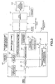
- Fig. 1 is a block diagram showing a configuration example of a digital signal recording apparatus according to an embodiment of the present invention.
- This digital signal recording apparatus records as a digital signal on a disc-shaped recording medium 100, a television broadcast program received by a tuner 11, a signal inputted from an external apparatus, and the like. It is possible to record a video signal and an audio signal on this disc-shaped recording medium 100 at any one of two recording modes, i.e., a high quality picture mode which lays stress on the picture quality admitting a short time of recording and a long time mode which lays stress on a long recording time admitting a lowered picture quality. These recording modes will be detailed later.
- the tuner 11 is used for selecting and receiving a television broadcast and isolates and demodulates for output an analog video signal, an analog audio signal and an accompanying data used for various controls. Operation of this tuner 11 is controlled by an operation system 61, a control system 62, and a reservation information from a timer (not depicted).
- a sound/data isolation block 12 the analog video signal, the analog video signal, and the accompanying data outputted from the tuner 11 are isolated from one another.
- the analog video signal is supplied via an input switching circuit 13 to an A/D converter 14.
- the analog audio signal is supplied to an A/D converter 34.
- the accompanying data outputted from the tuner 11 are control signals such as an audio signal mono/stereo decision signal and an EDTV decision signal which are supplied to a control system 62 for use in the high picture quality/long time mode decision and switching will be detailed later.
- the input switching circuit 13 is used to switch between an analog signal from the tuner 11 and an external input signal inputted from an external apparatus such as a satellite broadcast (BS) tuner.
- an external apparatus such as a satellite broadcast (BS) tuner.
- BS satellite broadcast
- the A/D converter 14 converts an analog video signal from the input switching circuit 13, into a video signal.
- a luminance (Y) signal and a color (C) signal of the digital video signal are isolated.
- a color demodulation circuit 16 two color difference signals Cr and Cb are demodulated from the isolated C signal.
- this Cr is a signal of a red (R) signal component deleted by the Y signal
- the Cb is a blue (B) signal component deleted by the Y signal.
- a digital input switching circuit 17 carries out switching between the Y signal from the Y/C isolation circuit 15 and two color difference signals Cr and Cb from the color demodulation circuit 16, and an external digital input signal such as a high quality picture broadcast.
- an external digital input signal such as a high quality picture broadcast.
- the data is used in the high quality picture/long time mode decision in the control system 62.
- the digital video signal selected here is transmitted to a pre-filter 18.
- the pre-filter 18 together with a resampling circuit 19 and a compression circuit 20 constitute main components of compression means for compressing a digital video signal to be recorded on the disc-shaped recording medium 100.
- the pre-filter 18 limits the digital video signal to a predetermined value of frequency band. This limit of the frequency band is carried out by reducing signal components of the video signal from a higher frequency side.
- a sampling rate is selected in the resampling circuit 19.
- the digital video signal from the resampling circuit 19 is compressed with a predetermined compression ratio according to the high quality picture/long time mode for supply to a multiplex circuit 41.
- the compression method used here may be MPEG (Moving Picture Experts Group) 1, MPEG 2, or the like.
- parameter switching for compression rate control and the like is carried out by a high quality picture/long time mode switching signal fed from the control system 62.
- a circuit configuration for carrying out compression at a variable rate will be detailed later with reference to Fig. 2.
- the audio signal from the input switching circuit 13 is converted into a digital audio signal by the A/D converter 34.
- a digital switching circuit 37 carries out switching between the digital audio signal and an external digital input signal, which is supplied via pre-filter 38, a resampling circuit 39, and a compression circuit 40 to the multiplex circuit 41. It should be noted that in each of these circuits, parameters are switched according to the high quality picture/long time mode switching signal fed from the control system 62 in the same way as for the video signal.
- the digital video data from the compression circuit 20 the digital audio data from the compression circuit 40, and the accompanying data, i.e., a control signal indicating the high quality picture/long tine mode fed from the control system 62 are converted into a serial data for supply to an FIFO (Fast In Fast Out) memory 42.
- FIFO Fast In Fast Out
- the FIFO memory 42 is a memory for accumulating digital signals compressed and accumulates a serial data from the multiplex circuit 41.
- the data accumulated in the FIFO memory 42 is read out in accordance with a transfer rate to the disc-shaped recording medium 100 and recorded on the disc-shaped medium 100 by predetermined recording means. It should be noted that this recording means is identical to a conventional one and its explanation will be omitted.
- the control system 62 carries out control such as a channel selection of the tuner 11 according to an instruction inputted from the operation system 61 and a reservation information specified in advance.
- the high quality picture mode is for recording with a lower compression ratio in order to lay stress on the picture quality admitting that the recording time per recording medium becomes shorter.
- the long time mode is for recording with a higher compression ratio in order to lay stress on the recording time admitting that the picture quality is lowered.
- it is assumed to carry out a variable rate recording that in the high quality picture mode, recording is carried out with a fixed rate using a constant compression ratio, whereas in the long time mode, recording is carried out by switching the compression ratio (recording bit rate).
- the number of pixels of the video signal is, for example, 704 x 480 pixels (60 fields/second) in the high quality picture mode and 352 x 240 pixels (30 frames/second) in the long time mode. These numbers are based on the existing video signal specifications.
- the former is based on the ITU-R601 (ITU-R: International Telecommunication Union-Radiocommunication Sector), and the latter is based on the SIF (Source Input Format) which is employed as specifications of a disc-shaped recording medium and the like using MPEG1 and called video CD.
- the number of pixels can be other than the aforementioned, but if the number of pixels in the high quality picture mode is equal to the number of pixels in the long time mode multiplied by an integer, it is possible to use a simple circuit configuration.
- the sampling frequency of the luminance (Y) signal of the video signal is 13.5 MHz and the sampling frequency of the two color difference signals Cr and Cb are respectively 6.75 MHz.
- Such a video signal is called a 4:2:2 video signal because of its sampling frequency ratio.
- the luminance (Y) signal of the video signal has a sampling frequency of 13.5 MHz which identical to the frequency in the high quality picture mode, and in the scanning lines of odd number, the sampling frequency of Cr is 6.75 MHz, and in the scanning lines of even numbers, the sampling frequency of Cb is 6.75 MHz.
- Such a video signal is called 4:1:0.
- the audio signal 20 kHz is assumed as the sampling frequency of a high quality sound mode which corresponds to the high quality picture mode, and 12 kHz is assumed in the long time mode.
- the aforementioned 4:2:2 video signal is limited to the maximum frequency of 6 MHz in the Y signal and the maximum frequency of 3 MHz in each of the two color difference signals Cr and Cb.
- the 4:1:0 video signal is limited to the maximum frequency of 3 MHz in the Y signal and to the maximum frequency of 1.5 MHz in each of the two color difference signals Cr and Cb.
- the compression ratio of the video signal is 6 Mbps in the high quality picture mode and 1 Mbps in the long time mode.
- the compression ratio of the audio signal is 128 kbps in the high quality picture mode and 64 kbps in the long time mode.
- Switching between the high quality picture mode and the long time mode is normally carried out manually by the user through the operation system 61, but it is also possible that the digital signal recording apparatus recognizes contents of a program to be recorded and automatically selects the mode.
- this category data is recognized to carry out the mode switching. For example, if a program to be recorded is a movie, the high quality picture mode is selected and if the program is a wide show, the long time mode is selected. It is also possible to store this mode setting in a timer (not depicted) or the like in the control system 2, and a series of programs which is broadcast every day or every week is recorded in the same mode unless the user changes the mode.
- the digital input switching circuit 17 and 37 are supplied from an external apparatus or the like with a digital input which is a high quality video signal and audio signal such as a high quality picture broadcast
- recording is carried out in the high quality picture mode.
- the aforementioned.high quality picture broadcast assumes the High-vision (HDTV) which is a Japanese method of high resolution television, a so-called Clear-vision broadcast (EDTV) which uses the number of scanning lines identical to the current television broadcast based on the NTSC method, a broadcast based on video signal specifications such as PAL+ employed outside Japan, and various digital broadcasts and the like.
- HDTV High-vision
- EDTV Clear-vision broadcast
- Fig. 2 is a block diagram showing a configuration example of the compression circuit 20 assuming to carry out the variable rate recording in the digital signal recording apparatus of Fig. 1.
- This compression circuit 20 is for compressing a video signal using a compression method such as the aforementioned MPEG or the like and further includes a function to change the recording bit rate according to a control signal fed from the control system 62 for specifying the high quality picture/long time mode to switch the compression ratio. Note that the method for changing the recording bit rate will be detailed later.
- the digital video signal from the resampling circuit 19 is supplied via a differential circuit 23 to a DCT circuit 24 and subjected to DCT (discrete cosine transform) which is a type of the orthogonal conversion, so as to be dissolved into frequency components.
- DCT discrete cosine transform
- a quantization block 25 the video signal which has been subjected to DCT in the DCT block 24 is quantized and compressed by removing a higher frequency term of the aforementioned frequency components. More specifically, each of the pixel values constituting a picture is divided by a divider of a certain value (quantization step) and a remainder is rounded. The rounded remainder will not be restored when the quantization step is multiplied during elongation-reproduction, thus realizing compression.
- quantization step it is necessary to increase the quantization step of the aforementioned divider. That is, if the quantization step is increased, most part of the higher frequency term becomes zero and the compression ratio is increased.
- a quantization conversion coefficient of the video signal quantized in the quantization block is transmitted to the multiplex circuit 41 and to a reverse quantization block 26.
- a reverse quantization is carried out according to a reversed procedure of the quantization in the quantization block.
- the quantization conversion coefficient which has been subjected to the reverse quantization is supplied to a reverse DCT block 27 and subjected to a reversed DCT (reverse discrete cosine transform) according to a reversed procedure of the DCT in the DCT block 24.
- a reversed DCT reverse discrete cosine transform
- An output from the reverse DCT block 27 is stored via an adder circuit 28 in a bidirectional motion compensation picture memory 29.
- An output from this bidirectional motion compensation picture memory 29 is returned to the adder circuit 28 to be added to an output from the aforementioned reverse DCT block 27, and the addition result is fetched again by the bidirectional motion compensation picture memory 29, an output of the bidirectional motion compensation picture memory 29 is also supplied as an inversion input to the aforementioned differential circuit 23 so as to create a difference from the digital video signal. This difference is the aforementioned digital video signal which is transmitted to the DCT block 24.
- a complexity detecting circuit 21 which is complexity detecting means.
- the most simple method to detect a complexity of a video signal is realized by detecting a quantity of a higher frequency component in a horizontal direction and vertical direction contained in the video signal. That is, a complexity of a video signal is determined according to the fact that a complicated picture having a plenty of fine parts contains more higher frequency components and a simple picture having small changes contains less higher frequency components.
- a detection result of the complexity is supplied to a bit rate control block 22, where the recording bit rate (i.e., compression ratio) is switched to the high quality picture mode or the long time mode specified by a control signal from the control system 62.
- the variable rate recording according to this recording bit rate will be detailed later.
- the bit rate control block 22 creates macro block types called I (Intra) picture, B (Bidirectionally predictive) picture, and P (Predictive) picture which are processed in different ways. These macro block types are supplied to the multiplex circuit 41.
- the control output of the recording bit rate is supplied to the quantization block 25 which will be detailed later and also supplied, as a quantization characteristic specification information to the multiplex block 41.
- the multiplex circuit 41 the aforementioned I, N, P macro block types, the quantization characteristic specification information, and the quantization conversion coefficient, as well as the audio data and an accompanying data such as various control signals are converted into a serial data and transmitted to the FIFO memory 42.
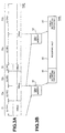
- Fig. 3 is a diagram for explanation of operation of the variable bit rate recording of the video signal by the compression circuit 20 shown in Fig. 2.
- a variable bit rate recording is carried out by changing the compression ratio according to the complexity of the video signal.
- the recording bit rate of a video signal assumes, for example, a 4 Mbps data for a complicated picture and a 1 Mbps data for a simple picture for every 0.1 seconds.
- the rotation velocity of the disc-shaped recording medium 100 is set to a mode identical to the high quality picture mode and a video signal is recorded for each of the sectors.
- the aforementioned recording operation is halted not to advance the tracking control.
- the tracking control is resumed when the video signal accumulated in the FIFO memory 42 becomes equal to or more than for one sector, so that recording operation is carried out in the next sector.
- a video signal 71 is outputted at 4 Mbps for 0.2 seconds; a video signal 72a and video signal 72b are outputted at 1 Mbps for a total of 0.4 seconds; a video signal 73 is outputted at 4 Mbps for 0.1 second; and video signals 74a and 74b are outputted at 1 Mbps for a total of 0.8 second.
- This compressed video signal is temporarily stored via the multiplex circuit 41 in the FIFO memory 42. If this FIFO memory has a capacity of 1 Mbit, at the moment when the compressed video signal of 1 M bit is accumulated in the FIFO memory, the accumulated signal is read out and transferred to the disc-shaped recording medium 100, completing one recording operation.
- Fig. 3B shows this recording operation.
- 5 Mbps is assumed as the recording rate to the disc-shaped recording medium 100
- the operation of recording the 1 Mbit video signal from the FIFO memory 42 is complete in 0.2 seconds. That is, in the first one recording operation 81, the video signal 71 of 4 Mbps for 0.2 seconds and the video signal 72a of 1 Mbps for 0.2 seconds are transferred to be recorded onto the disc-shaped recording medium 100.
- the recording operation is halted as shown by the recording halt time 82 in the figure.
- the next recording operation 83 is started when another 1 Mbit video signal is accumulated in the FIFO memory 42.
- the video signal 72 of 1 Mbps for 0.2 seconds, the video signal 73 of 4 Mbps for 0.1 second, and the video signal 74a of 1 Mbps for 0.4 seconds are transferred to be recorded onto the disc-shaped recording medium 100.
- the disc-shaped recording medium 100 is an optical disc
- tracking of an optical pickup (head) is terminated at the moment when one recording operation is complete. And at the moment when a 1 Mbit video data is accumulated in the FIFO memory 42, the tracking of the optical pickup is started for carrying out recording operation. Consequently, the recording halt time 82 is decreased if video signals of complicated pictures are successively outputted and the recording halt time 82 is increased if video signals of simple pictures are successively outputted.
- the recording bit rate is averaged, carrying out a variable rate recording.
- the input signal specification is SIF (Source Input Format)
- SIF Source Input Format
- variable rate recording In the long time mode, the aforementioned variable rate recording is carried out and in the high quality picture mode, fixed rate recording is carried out. Switching between the high quality picture/long time modes is carried out by a mode switching instruction transmitted from the control system 62 to the bit rate control circuit 22.
- variable rate recording In a case when one or two programs can be recorded on a single disc-shaped recording medium 100, if a variable rate recording is carried out in the high quality picture mode, a target program may not be recorded continuously because the recording time is changed.
- a variable rate recording enables to record many programs on the disc-shaped recording medium 100 and the entire recording time is not greatly changed although the respective program recording time values may be changed.
- this long time mode is for recording a plenty of programs, it is rather preferable that the recording bit rate can be lowered by the variable rate recording.
- variable recording bit rate is used only in the long time mode and the fixed bit rate is used in the high quality picture mode.
- the transfer rate of the video signal to the disc-shaped recording medium 100 is made greater than the aforementioned 5 Mbps (for example 8 Mbps), and the average transfer rate is made to be 5 Mbps while accumulating the video signal in the FIFO memory 42, thus enabling to carry out recording/reproduction of further higher quality picture.
- Fig. 4 shows an example of recording area arrangement when recording a compressed digital signal in the high quality picture mode and a compressed digital signal in the long time mode.
- a relative velocity (linear velocity) between the head and the disc is controlled to be constant.
- a digital signal of the high quality picture mode is recorded at a relative velocity 2 m/s in a recording area 100b provided on the outer circumferential side of the disc-shaped recording medium, starting at the outermost circumference.
- a digital signal of the long time mode is recorded at a relative velocity of 1 m/s from in a recording area 100a provided on the inner circumferential side of the disc-shaped recording medium 100, starting at the innermost circumeference.
- the recording areas are allocated thus on the disc-shaped recording medium 100, it is possible to minimize the change of the number of rotations to control to obtain a constant relative velocity for the respective recording modes. As a result, it is possible to reduce the load on a spindle servo driving to rotate the disc-shaped recording medium 100 as well as to reduce a recording signal retrieval time.
- the disc-shaped recording medium 100 is a magnetic disc (hard disc)
- the disc-shaped recording medium 100 is normally driven at a constant number of rotations. If the recording areas arranged on the hard disc in the same way as in the aforementioned optical disc, a video signal of the long time mode having a greater compression ratio (greater transfer rate) is recorded on the disc inner circumeferential side whether the relative velocity between the head and the disc is lowered and accordingly, it is possible to substantially increase the transfer rate of the signal recorded on the inner circumferential side, which enables to reduce load of hardware such as reducing the size of a cache memory used for making constant the transfer rate to outside.
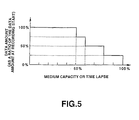
- Fig. 5 shows that the compression ratio is switched from one to another according to the empty capacity (remaining recordable capacity) of the recording medium and the recording time lapse. It is also possible to continuously change the compression ratio, but it is more practical to change in a stepped way as shown in Fig. 5.
- the compression ratio is switched between two steps.
- the horizontal axis represents a capacity of the recording medium 100 as a ratio with respect to the capacity at the recording start and the vertical axis represents a signal data amount recorded on the recording medium 100 as a ratio with respect to the data amount at the recording start.
- a video signal, audio signal, and the like to be recorded on the recording medium 100 are controlled so that a data amount is compressed to 75% compared to the data amount at the recording start.
- the compression ratio is increased so that a signal data amount to be recorded on the recording medium 100 is compressed to 50% compared to the recording start.
- the compression ratio is controlled to be increased so that a signal data amount to be recorded on the recording medium 100 is compressed to 25% of that at the recording start.
- Switching of the compression ratio can be realized by a method of limiting a frequency band of an input signal; a method of switching a sampling frequency of an input signal; a method of frame discarding, and the like. Furthermore, it is possible to carry out zone encoding, changing characteristic of a reproduction filter in the digital signal reproduction apparatus, and other various methods. Hereinafter, explanation will be given on several methods for compression ratio switching.
- Fig. 6 shows a method of changing the frequency band of a signal to be compressed for changing the compression ratio.
- a signal frequency whose gain is limited is f 1 in Fig. 6A, f 2 in Fig. 6B, f 3 in Fig. 6C, and f 4 in Fig. 6D.
- f 1 > f 2 > f 3 > f 4 it is assumed that signal frequency components are successively limited starting at the higher frequency.
- this signal is a video signal, signal components expressing fine parts of a picture are successively reduced and as the data amount is decreased, the picture sharpness is deteriorated from Fig. 6A toward Fig. 6D.
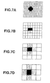
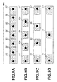
- Fig. 7 shows a method of compression ratio switching of a video signal by changing a number of blocks constituting a screen, i.e., by changing the resolution. From Fig. 7A toward Fig. 7D, the number of blocks constituting a screen is decreased, lowering the resolution. Thus, a data amount required for one screen is reduced and the signal is substantially compressed.
- Fig. 8 shows a method for compression ratio switching by changing the display image. From Fig. 8A toward Fig. 8D, the size of one screen image is decreased. In Fig. 8A to Fig. 8D, although the size of a block constituting the screen is identical, the number of blocks constituting a screen is reduced. Thus, a necessary data amount is decreased and the signal is substantially compressed.
- Fig. 9 schematically shows a method to change the compression ratio by changing the number of frames per a unit time.
- one screen consists of 7 frames per a unit time.
- Fig. 9A shows 7 frames of Frame 91 to Frame 97 arranged within the aforementioned unit time so as to constitute one screen.
- a black circle in the frames shows an object moving from left to right in the screen.
- Fig. 9B two frames of Frame 93 and Frame 96 are removed from the aforementioned 7 frames, and the remaining 5 frames are arranged at an identical time interval within the aforementioned unit time.
- frame 92a may be frame 92 or frame 93 as they are. However, it is more preferable to create frame 92a by the average processing or interpolation processing between frame 92 and frame 93. The same applies to frame 95a. With this operation, the video signal is compressed to 5/7.
- Fig. 9C three frames of frame 92, frame 94, and frame 96 are removed from the aforementioned 7 frames, and the remaining 4 frames are arranged within the unit time. With this operation, the video signal is compressed to 4/7.
- Fig. 9D four frames of frame 92, frame 93, frame 95, and frame 96 are removed from the aforementioned 7 frames, and the remaining 3 frames are arranged within the unit time. With this operation, the video signal is compressed to 3/7.
- the compression ratio it is possible to change the compression ratio by changing the number of frames to be removed from the frames constituting one screen of a video signal per a unit time.
- the frame removal (thinning) value increases, the compression ratio is increased. It should be noted that in a space created by removal of a frame, the old frame is retained.
- the thinning ratio is changed to control the compression ratio.
- the thinning ratio is increased.
- Fig. 10 schematically shows the aforementioned methods of variable rate recording in the long time recording mode, so as to change the compression ratio of a digital signal according to an empty capacity of the recording medium and the recording time.
- the compression ratio is continuously changed according to the time, but as has been described above, the compression ratio is practically switched between several steps.
- the compression ratio is changed linearly, but as shown in Fig. 10B, it is also possible to linearly change the compression ratio from the recording start.
- the compression ratio is changed by using a non-linear function such as a fractional function, exponential function, and logarithmic function, or as shown in Fig. 10D, it is also to change the compression ratio in a curve from the recording start.
- the transfer rate is also increased.
- the maximum compression ratio be such that a data amount is compressed to 20% of the data amount at the recording start.
- the aforementioned methods for changing the recording bit rate can be used in combination according to the necessity.
- zone encoding for substantially increasing the compression ratio. That is, in a screen consisting of a digital signal inputted, the number of bits allocated for the peripheral portion is decreased more than the decrease of the allocated bits for the center portion. This is based on the following. In the long time mode, the compression ratio is comparatively high and the reproduction signal bit rate is lowered, often causing block distortion and mosquito noise. To cope with this, more bits are allocated for the screen center portion where more important contents are normally displayed than the screen peripheral portion.
- Fig. 11 is a block diagram showing a configuration example of the digital signal reproduction apparatus which corresponds to the digital signal recording apparatus shown in Fig. 1.
- This digital signal reproduction apparatus is for reproducing a digital signal such as a video signal and an audio signal which have been compressed in the aforementioned high quality picture mode or the long time mode before being recorded on the disc-shaped recording medium 100.
- those components common to the components in the digital signal recording apparatus of Fig. 1 are denoted with the identical symbols.
- a compressed digital signal such as a video signal which is read out from the disc-shaped recording medium 100 by predetermined read-out means is accumulated in the FIFO memory 42 so as to be converted into a continuous data, and the signal is dissolved in a demultiplex circuit 42 into a video signal, audio signal, and accompanying data.
- This accompanying data is a control signal including a high quality picture/long time mode switching signal.
- the video signal isolated in the demultiplex circuit 43 is decoded from the compressed state by a compression decoding circuit 44 serving as decoding means and is subjected to pre-filtering by in a post-filter 45 using a parameter selected according to the high quality picture/long time mode switching signal.
- the signal is further encoded by an NTSC encoder 46 and converted by a D/A converter 47 into an analog video signal for output.
- the audio signal which has been isolated in the demultiplex circuit 43 is decoded from the compressed state by a compression decoding circuit 54 and subjected to filtering by a post-filter 55 using a parameter selected according to the high quality picture/long time mode switching signal.
- the signal is further encoded by an NTSC encoder 56 and converted by a D/A converter 57 into an analog audio signal for output.
- Fig. 11 shows a configuration example for a case when the video signal is based on the signal specification of the NTCS method.
- a video signal specification other than the NTSC method such as the PAL method and the SECAM method.
- the NTSC encoders 46 and 56 are replace by encoders satisfying the video signal specifications.
- Fig. 12 is a block diagram showing a configuration example of the post-filter 45 in Fig. 11.
- the compression ratio of a video signal is set to a comparatively high value in order to prolong the time available for recording the video signal on the disc-shaped recording medium 100.
- a block distortion may remain in the picture reproduced.
- This block distortion may be reduced by filtering with the post-filter 45 during reproduction.
- FNR field noise reduction
- a video signal of one field or one frame decoded by a compression decoding circuit 44 is accumulated in a memory 45a and is subtracted from the next one field or one frame of video signal in a differential circuit 45b so as to obtain a difference.
- This difference is limited to a certain value or below by a limitter circuit 45c and is supplied via an attenuator 45d to a differential circuit 45e.
- the attenuation amount of this attenuator 45d is controlled according to the high quality picture/long time mode switching signal.
- the differential circuit 45e the difference from the attenuator 45e is subtracted from a video signal supplied from the compression decoding circuit 44 for output to the NTSC encoder 46.
- a digital signal is compressed with a compression ratio specified from a plurality of compression ratios by a control signal and accordingly, it is possible to record a video signal in the high quality picture mode and in the long time mode having different compression ratios on one disc-shaped recording medium capable of recording a video signal.
- the aforementioned digital signal recording method and apparatus are used to reproduce a digital signal recorded with different compression ratios on one disc-shaped recording medium and the signal is subjected to a processing to reduce a block distortion according to the respective compression ratios before being output. Consequently, it is possible to reproduce with a practical picture quality even a video signal recorded in the long time mode with a high compression ratio.
Landscapes
- Engineering & Computer Science (AREA)
- Multimedia (AREA)
- Signal Processing (AREA)
- Television Signal Processing For Recording (AREA)
- Signal Processing For Digital Recording And Reproducing (AREA)
Applications Claiming Priority (3)
| Application Number | Priority Date | Filing Date | Title |
|---|---|---|---|
| JP3242497 | 1997-02-17 | ||
| JP9032424A JPH10228728A (ja) | 1997-02-17 | 1997-02-17 | デジタル信号記録方法及び装置、デジタル信号再生方法及び装置 |
| JP32424/97 | 1997-02-17 |
Publications (3)
| Publication Number | Publication Date |
|---|---|
| EP0859523A2 EP0859523A2 (en) | 1998-08-19 |
| EP0859523A3 EP0859523A3 (en) | 2000-04-19 |
| EP0859523B1 true EP0859523B1 (en) | 2003-04-16 |
Family
ID=12358582
Family Applications (1)
| Application Number | Title | Priority Date | Filing Date |
|---|---|---|---|
| EP98300963A Expired - Lifetime EP0859523B1 (en) | 1997-02-17 | 1998-02-10 | Digital signal recording and/or reproduction methods and apparatus |
Country Status (7)
| Country | Link |
|---|---|
| US (1) | US6115341A (enExample) |
| EP (1) | EP0859523B1 (enExample) |
| JP (1) | JPH10228728A (enExample) |
| KR (1) | KR19980071371A (enExample) |
| CN (1) | CN1178528C (enExample) |
| DE (1) | DE69813343T2 (enExample) |
| ES (1) | ES2192742T3 (enExample) |
Families Citing this family (53)
| Publication number | Priority date | Publication date | Assignee | Title |
|---|---|---|---|---|
| US6876617B1 (en) * | 1997-07-01 | 2005-04-05 | Sanyo Electric Co., Ltd. | Recording medium, recorder, and player |
| SG82587A1 (en) * | 1997-10-21 | 2001-08-21 | Sony Corp | Recording apparatus, recording method, playback apparatus, playback method, recording/playback apparatus, recording/playback method, presentation medium and recording medium |
| TW385436B (en) | 1997-12-12 | 2000-03-21 | Toshiba Corp | Digital recording system using variable recording rate |
| JP4182369B2 (ja) * | 1998-05-29 | 2008-11-19 | ソニー株式会社 | 記録再生装置および方法、並びに記録媒体 |
| JP2000101658A (ja) * | 1998-09-24 | 2000-04-07 | Victor Co Of Japan Ltd | インターフェース回路 |
| WO2000025312A1 (fr) * | 1998-10-27 | 2000-05-04 | Hitachi Maxell, Ltd. | Procede et systeme d'enregistrement d'informations, systeme de compression/decompression d'images, procede de commande de ces systemes, et systeme de controle comprenant une partie ou la totalite des systemes precedents |
| US6205499B1 (en) * | 1998-12-18 | 2001-03-20 | The United States Of America As Represented By The Secretary Of The Navy | System for compressing video data using bi-orthogonal wavelet coding having a DSP for adjusting compression ratios to maintain a constant data flow rate of the compressed data |
| US6564005B1 (en) | 1999-01-28 | 2003-05-13 | International Business Machines Corporation | Multi-user video hard disk recorder |
| SE522856C2 (sv) * | 1999-01-29 | 2004-03-09 | Axis Ab | En datalagrings- och reduceringsmetod för digitala bilder, samt ett övervakningssystem som använder nämnda metod |
| KR100324746B1 (ko) * | 1999-04-24 | 2002-02-20 | 구자홍 | 음성 청취가 가능한 디지탈 데이터 플레이어 |
| JP4489248B2 (ja) * | 1999-06-02 | 2010-06-23 | パナソニック株式会社 | 光ディスク、光ディスクに対してデータの記録、再生を行なう装置及び方法 |
| US6504995B1 (en) * | 1999-07-21 | 2003-01-07 | Hewlett-Packard Company | Apparatus and method for storing compressed data to a storage device |
| JP4004695B2 (ja) * | 1999-10-04 | 2007-11-07 | パイオニア株式会社 | 情報記録装置 |
| JP4501187B2 (ja) | 1999-10-22 | 2010-07-14 | ソニー株式会社 | 情報処理装置、情報処理システム及び情報処理方法 |
| EP1104196A3 (en) * | 1999-11-09 | 2004-06-16 | Denon, Ltd. | Device for data compression and storage |
| US6741650B1 (en) | 2000-03-02 | 2004-05-25 | Adc Telecommunications, Inc. | Architecture for intermediate frequency encoder |
| US6766100B1 (en) * | 2000-10-19 | 2004-07-20 | Ati International Srl | Method and apparatus for multi-TV tuner display of video information |
| US20020136538A1 (en) * | 2001-03-22 | 2002-09-26 | Koninklijke Philips Electronics N.V. | Smart quality setting for personal TV recording |
| EP1374600A1 (en) * | 2001-03-26 | 2004-01-02 | Koninklijke Philips Electronics N.V. | Storage of multi-media items |
| JP2003199045A (ja) * | 2001-12-26 | 2003-07-11 | Victor Co Of Japan Ltd | 情報記録信号の生成方法、情報信号の再生方法、情報信号の伝送方法、情報記録信号生成装置、情報信号再生装置、情報信号伝送装置、情報信号記録媒体、及び情報信号伝送用プログラム |
| US6993285B2 (en) * | 2002-04-11 | 2006-01-31 | International Business Machines Corporation | Audio buffer processing |
| JP4162454B2 (ja) * | 2002-09-10 | 2008-10-08 | 三洋電機株式会社 | データ処理装置 |
| JP3712204B2 (ja) * | 2002-10-31 | 2005-11-02 | ソニー株式会社 | 記録再生装置 |
| KR20040104237A (ko) * | 2003-06-03 | 2004-12-10 | 삼성전자주식회사 | 압축방식을 자동으로 설정하는 촬영장치 및 방법 |
| JP2005033622A (ja) * | 2003-07-08 | 2005-02-03 | Matsushita Electric Ind Co Ltd | 映像信号記録装置および映像信号記録方法 |
| JP4101780B2 (ja) * | 2004-03-22 | 2008-06-18 | 株式会社日立国際電気 | 信号伝送方法および信号伝送装置 |
| US7920169B2 (en) | 2005-01-31 | 2011-04-05 | Invention Science Fund I, Llc | Proximity of shared image devices |
| US7876357B2 (en) | 2005-01-31 | 2011-01-25 | The Invention Science Fund I, Llc | Estimating shared image device operational capabilities or resources |
| US20060170956A1 (en) * | 2005-01-31 | 2006-08-03 | Jung Edward K | Shared image devices |
| US8606383B2 (en) | 2005-01-31 | 2013-12-10 | The Invention Science Fund I, Llc | Audio sharing |
| US9124729B2 (en) | 2005-01-31 | 2015-09-01 | The Invention Science Fund I, Llc | Shared image device synchronization or designation |
| US8902320B2 (en) | 2005-01-31 | 2014-12-02 | The Invention Science Fund I, Llc | Shared image device synchronization or designation |
| US20060174203A1 (en) | 2005-01-31 | 2006-08-03 | Searete Llc, A Limited Liability Corporation Of The State Of Delaware | Viewfinder for shared image device |
| US9489717B2 (en) | 2005-01-31 | 2016-11-08 | Invention Science Fund I, Llc | Shared image device |
| US9325781B2 (en) | 2005-01-31 | 2016-04-26 | Invention Science Fund I, Llc | Audio sharing |
| US9082456B2 (en) | 2005-01-31 | 2015-07-14 | The Invention Science Fund I Llc | Shared image device designation |
| US9910341B2 (en) | 2005-01-31 | 2018-03-06 | The Invention Science Fund I, Llc | Shared image device designation |
| US9967424B2 (en) | 2005-06-02 | 2018-05-08 | Invention Science Fund I, Llc | Data storage usage protocol |
| US7782365B2 (en) | 2005-06-02 | 2010-08-24 | Searete Llc | Enhanced video/still image correlation |
| US9819490B2 (en) | 2005-05-04 | 2017-11-14 | Invention Science Fund I, Llc | Regional proximity for shared image device(s) |
| US9942511B2 (en) | 2005-10-31 | 2018-04-10 | Invention Science Fund I, Llc | Preservation/degradation of video/audio aspects of a data stream |
| US9001215B2 (en) | 2005-06-02 | 2015-04-07 | The Invention Science Fund I, Llc | Estimating shared image device operational capabilities or resources |
| US10003762B2 (en) | 2005-04-26 | 2018-06-19 | Invention Science Fund I, Llc | Shared image devices |
| US8681225B2 (en) | 2005-06-02 | 2014-03-25 | Royce A. Levien | Storage access technique for captured data |
| US9451200B2 (en) | 2005-06-02 | 2016-09-20 | Invention Science Fund I, Llc | Storage access technique for captured data |
| US9093121B2 (en) | 2006-02-28 | 2015-07-28 | The Invention Science Fund I, Llc | Data management of an audio data stream |
| JP4769695B2 (ja) * | 2005-12-16 | 2011-09-07 | キヤノン株式会社 | 撮像装置及び再生装置 |
| CN100591111C (zh) * | 2005-12-16 | 2010-02-17 | 佳能株式会社 | 摄像设备和摄像方法以及再现设备和再现方法 |
| JP2009100461A (ja) * | 2007-09-28 | 2009-05-07 | Sanyo Electric Co Ltd | 映像記録再生装置、映像記録装置、及び映像符号化装置。 |
| JP4565358B2 (ja) * | 2008-07-01 | 2010-10-20 | ソニー株式会社 | 編集装置及び編集方法 |
| CN101931773A (zh) * | 2009-06-23 | 2010-12-29 | 虹软(杭州)多媒体信息技术有限公司 | 视频处理方法 |
| CN102169134A (zh) * | 2010-12-17 | 2011-08-31 | 中国电力科学研究院 | 一种基于硬件的暂态电压记录方法 |
| US9313300B2 (en) * | 2013-11-07 | 2016-04-12 | Integrated Device Technology, Inc. | Methods and apparatuses for a unified compression framework of baseband signals |
Family Cites Families (7)
| Publication number | Priority date | Publication date | Assignee | Title |
|---|---|---|---|---|
| JP3141241B2 (ja) * | 1990-08-24 | 2001-03-05 | ソニー株式会社 | ディスク記録装置及びディスク再生装置 |
| JP2507174B2 (ja) * | 1990-11-20 | 1996-06-12 | 松下電器産業株式会社 | 光ディスク装置 |
| AU678490B2 (en) * | 1993-07-12 | 1997-05-29 | Sony Corporation | Decoding method and apparatus |
| JPH087478A (ja) * | 1994-06-20 | 1996-01-12 | Pioneer Video Corp | 圧縮画像情報の記録装置 |
| DE69524023T2 (de) * | 1994-09-26 | 2002-06-20 | Matsushita Electric Industrial Co., Ltd. | Aufnahmevorrichtung für digitale Signale |
| MY114287A (en) * | 1994-12-26 | 2002-09-30 | Sony Corp | Digital video recorder |
| JP3774914B2 (ja) * | 1995-09-27 | 2006-05-17 | ソニー株式会社 | ビデオ装置 |
-
1997
- 1997-02-17 JP JP9032424A patent/JPH10228728A/ja active Pending
-
1998
- 1998-02-09 US US09/020,691 patent/US6115341A/en not_active Expired - Lifetime
- 1998-02-10 ES ES98300963T patent/ES2192742T3/es not_active Expired - Lifetime
- 1998-02-10 EP EP98300963A patent/EP0859523B1/en not_active Expired - Lifetime
- 1998-02-10 DE DE69813343T patent/DE69813343T2/de not_active Expired - Lifetime
- 1998-02-16 KR KR1019980004516A patent/KR19980071371A/ko not_active Ceased
- 1998-02-17 CN CNB981082815A patent/CN1178528C/zh not_active Expired - Lifetime
Also Published As
| Publication number | Publication date |
|---|---|
| DE69813343D1 (de) | 2003-05-22 |
| EP0859523A2 (en) | 1998-08-19 |
| EP0859523A3 (en) | 2000-04-19 |
| JPH10228728A (ja) | 1998-08-25 |
| DE69813343T2 (de) | 2004-02-12 |
| ES2192742T3 (es) | 2003-10-16 |
| US6115341A (en) | 2000-09-05 |
| KR19980071371A (ko) | 1998-10-26 |
| CN1178528C (zh) | 2004-12-01 |
| CN1198066A (zh) | 1998-11-04 |
Similar Documents
| Publication | Publication Date | Title |
|---|---|---|
| EP0859523B1 (en) | Digital signal recording and/or reproduction methods and apparatus | |
| US5949953A (en) | Disk media, and method of and device for recording and playing back information on or from a disk media | |
| EP1043893B1 (en) | Image processing apparatus | |
| JP4616942B2 (ja) | 情報担体を介する同時記録及び再生用記録及び再生装置 | |
| JP3465272B2 (ja) | デジタルデータ記録装置および記録方法 | |
| JP3008995B2 (ja) | ディジタルビデオ信号の磁気記録装置 | |
| KR0135872B1 (ko) | 디지탈 영상기록재생장치 및 그 방법 | |
| JPH07107359A (ja) | 撮像装置 | |
| JP3564087B2 (ja) | 映像記録再生装置 | |
| JP2004282780A (ja) | 撮像装置 | |
| EP0772366B1 (en) | A digital recording/reproducing apparatus | |
| JPH10234000A (ja) | 信号記録方法及び装置、記録媒体、信号再生方法及び装置、信号記録再生装置 | |
| JP3619250B2 (ja) | カメラ一体型画像記録再生装置 | |
| US20040240849A1 (en) | Video recording and reproducing apparatus and video recording and reproducing method | |
| JP3288134B2 (ja) | カメラ一体型映像記録装置 | |
| KR100813063B1 (ko) | 고속 포워딩 및 리와인딩 디스플레이 기능을 갖는 영상장치 및 그 방법 | |
| JP3487557B2 (ja) | 画像処理装置及びその方法 | |
| JP2005229645A (ja) | 画像記録再生装置 | |
| JPH054684U (ja) | 高画質tv信号変換回路内蔵vtr | |
| JP2005278199A (ja) | 撮像装置及び画像処理方法 | |
| JPH06253256A (ja) | ビデオ信号出力装置、ビデオ信号記録装置およびビデオ信号記録媒体 |
Legal Events
| Date | Code | Title | Description |
|---|---|---|---|
| PUAI | Public reference made under article 153(3) epc to a published international application that has entered the european phase |
Free format text: ORIGINAL CODE: 0009012 |
|
| AK | Designated contracting states |
Kind code of ref document: A2 Designated state(s): DE ES FR GB |
|
| AX | Request for extension of the european patent |
Free format text: AL;LT;LV;MK;RO;SI |
|
| PUAL | Search report despatched |
Free format text: ORIGINAL CODE: 0009013 |
|
| AK | Designated contracting states |
Kind code of ref document: A3 Designated state(s): AT BE CH DE DK ES FI FR GB GR IE IT LI LU MC NL PT SE |
|
| AX | Request for extension of the european patent |
Free format text: AL;LT;LV;MK;RO;SI |
|
| RIC1 | Information provided on ipc code assigned before grant |
Free format text: 7H 04N 5/85 A |
|
| 17P | Request for examination filed |
Effective date: 20000927 |
|
| AKX | Designation fees paid |
Free format text: DE ES FR GB |
|
| 17Q | First examination report despatched |
Effective date: 20010110 |
|
| GRAG | Despatch of communication of intention to grant |
Free format text: ORIGINAL CODE: EPIDOS AGRA |
|
| GRAG | Despatch of communication of intention to grant |
Free format text: ORIGINAL CODE: EPIDOS AGRA |
|
| GRAH | Despatch of communication of intention to grant a patent |
Free format text: ORIGINAL CODE: EPIDOS IGRA |
|
| GRAH | Despatch of communication of intention to grant a patent |
Free format text: ORIGINAL CODE: EPIDOS IGRA |
|
| GRAA | (expected) grant |
Free format text: ORIGINAL CODE: 0009210 |
|
| AK | Designated contracting states |
Designated state(s): DE ES FR GB |
|
| REG | Reference to a national code |
Ref country code: GB Ref legal event code: FG4D |
|
| REF | Corresponds to: |
Ref document number: 69813343 Country of ref document: DE Date of ref document: 20030522 Kind code of ref document: P |
|
| REG | Reference to a national code |
Ref country code: ES Ref legal event code: FG2A Ref document number: 2192742 Country of ref document: ES Kind code of ref document: T3 |
|
| ET | Fr: translation filed | ||
| PLBE | No opposition filed within time limit |
Free format text: ORIGINAL CODE: 0009261 |
|
| STAA | Information on the status of an ep patent application or granted ep patent |
Free format text: STATUS: NO OPPOSITION FILED WITHIN TIME LIMIT |
|
| 26N | No opposition filed |
Effective date: 20040119 |
|
| REG | Reference to a national code |
Ref country code: DE Ref legal event code: R084 Ref document number: 69813343 Country of ref document: DE |
|
| REG | Reference to a national code |
Ref country code: DE Ref legal event code: R084 Ref document number: 69813343 Country of ref document: DE Effective date: 20150410 |
|
| REG | Reference to a national code |
Ref country code: FR Ref legal event code: PLFP Year of fee payment: 19 |
|
| REG | Reference to a national code |
Ref country code: FR Ref legal event code: PLFP Year of fee payment: 20 |
|
| PGFP | Annual fee paid to national office [announced via postgrant information from national office to epo] |
Ref country code: FR Payment date: 20170217 Year of fee payment: 20 Ref country code: DE Payment date: 20170217 Year of fee payment: 20 |
|
| PGFP | Annual fee paid to national office [announced via postgrant information from national office to epo] |
Ref country code: GB Payment date: 20170216 Year of fee payment: 20 |
|
| PGFP | Annual fee paid to national office [announced via postgrant information from national office to epo] |
Ref country code: ES Payment date: 20170213 Year of fee payment: 20 |
|
| REG | Reference to a national code |
Ref country code: DE Ref legal event code: R071 Ref document number: 69813343 Country of ref document: DE |
|
| REG | Reference to a national code |
Ref country code: GB Ref legal event code: PE20 Expiry date: 20180209 |
|
| PG25 | Lapsed in a contracting state [announced via postgrant information from national office to epo] |
Ref country code: GB Free format text: LAPSE BECAUSE OF EXPIRATION OF PROTECTION Effective date: 20180209 |
|
| REG | Reference to a national code |
Ref country code: ES Ref legal event code: FD2A Effective date: 20180525 |
|
| PG25 | Lapsed in a contracting state [announced via postgrant information from national office to epo] |
Ref country code: ES Free format text: LAPSE BECAUSE OF EXPIRATION OF PROTECTION Effective date: 20180211 |