EP0856692A1 - Dispositif de positionnement de la queue d'une soupage - Google Patents
Dispositif de positionnement de la queue d'une soupage Download PDFInfo
- Publication number
- EP0856692A1 EP0856692A1 EP98101125A EP98101125A EP0856692A1 EP 0856692 A1 EP0856692 A1 EP 0856692A1 EP 98101125 A EP98101125 A EP 98101125A EP 98101125 A EP98101125 A EP 98101125A EP 0856692 A1 EP0856692 A1 EP 0856692A1
- Authority
- EP
- European Patent Office
- Prior art keywords
- cage
- valve
- expansion body
- housing
- tappet
- Prior art date
- Legal status (The legal status is an assumption and is not a legal conclusion. Google has not performed a legal analysis and makes no representation as to the accuracy of the status listed.)
- Ceased
Links
- 230000006835 compression Effects 0.000 claims description 11
- 238000007906 compression Methods 0.000 claims description 11
- 238000010438 heat treatment Methods 0.000 claims description 9
- 230000001419 dependent effect Effects 0.000 claims description 5
- 230000004323 axial length Effects 0.000 description 2
- 230000000694 effects Effects 0.000 description 2
- 239000008236 heating water Substances 0.000 description 2
- XLYOFNOQVPJJNP-UHFFFAOYSA-N water Substances O XLYOFNOQVPJJNP-UHFFFAOYSA-N 0.000 description 2
- 230000009286 beneficial effect Effects 0.000 description 1
- 238000005485 electric heating Methods 0.000 description 1
- 238000005516 engineering process Methods 0.000 description 1
- 238000009434 installation Methods 0.000 description 1
- 230000003993 interaction Effects 0.000 description 1
- 238000009423 ventilation Methods 0.000 description 1
Images

Classifications
-
- F—MECHANICAL ENGINEERING; LIGHTING; HEATING; WEAPONS; BLASTING
- F24—HEATING; RANGES; VENTILATING
- F24D—DOMESTIC- OR SPACE-HEATING SYSTEMS, e.g. CENTRAL HEATING SYSTEMS; DOMESTIC HOT-WATER SUPPLY SYSTEMS; ELEMENTS OR COMPONENTS THEREFOR
- F24D19/00—Details
- F24D19/10—Arrangement or mounting of control or safety devices
- F24D19/1006—Arrangement or mounting of control or safety devices for water heating systems
- F24D19/1009—Arrangement or mounting of control or safety devices for water heating systems for central heating
- F24D19/1015—Arrangement or mounting of control or safety devices for water heating systems for central heating using a valve or valves
-
- G—PHYSICS
- G05—CONTROLLING; REGULATING
- G05D—SYSTEMS FOR CONTROLLING OR REGULATING NON-ELECTRIC VARIABLES
- G05D23/00—Control of temperature
- G05D23/19—Control of temperature characterised by the use of electric means
- G05D23/1919—Control of temperature characterised by the use of electric means characterised by the type of controller
- G05D23/1921—Control of temperature characterised by the use of electric means characterised by the type of controller using a thermal motor
Definitions
- the invention relates to a device for adjusting the tappet of a valve is acted upon by a return spring and is adjustable in its axial direction from a housing that can be firmly connected to the valve, in which one with a working piston Equipped, temperature-dependent expansion body is attached so that the axes of The plunger and the working piston run in the same direction in which the expansion body of a pot-like cage, adjustable in its axial direction, with one on its open End is surrounded at right angles to the outside projecting surface, in which one of the Compression spring surrounding the cage with larger compared to the return spring of the valve Spring force is present, with one end on the contact surface of the cage and with the supported at the other end on the housing and in through the working piston of the expansion body Axial direction is compressible and in which an electrical on the expansion body Heating resistor is attached (DE 31 40 472 C2).
- Such an arrangement is used, for example, in heating and ventilation technology used. In principle, it can be used wherever there is a valve Adjustment movement is to be carried out. It can, for example, flaps moved or clear pipe cross sections are changed.
- the compression spring is mounted in a rigid section in the the approach of the pressure element engages.
- the housing is almost twice as high as the expansion body. It is also relatively wide, since the expansion body, the tension spring and the pressure element are at a distance are arranged next to each other.
- the plunger of the Valve moved by electric current.
- the device is with a temperature-dependent expansion body equipped with an electrical heating resistor is appropriate.
- a signal supplied by a thermostat, for example, causes the Heating resistor is switched on.
- the working piston is then generated by the heat of the expansion body so that the compression spring is compressed.
- the pestle of the in relieves the closed position of the valve and the return spring Moved in the direction of "valve opening”.
- This known device has been put into practice proven. However, it has a relatively large number of individual parts. It also builds relatively high, so it can protrude into a room.
- the invention has for its object the device described above to further develop that with a small overall height and simple assembly with few individual parts gets along.
- This device consists of only a few individual parts. It is therefore simple assemble. Due to the eccentric mounting in relation to the valve stem of the expansion body, the plunger on the one hand and the working piston of the expansion body move when operating the device in different levels, which are next to each other. Of the Adjustment path of the plunger therefore needs this for dimensioning the overall height of the housing Device not to be considered.
- the overall height of the housing can overall essentially limited to the axial length of the expansion body itself and to keep it as small as possible.
- the eccentric, lateral position of the expansion body also a space in which may be needed electrical or electronic components can be accommodated.
- the invention is described below for use in a hot water heating system described without being restricted to this area of application.
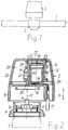
- FIG. 1 a section of a pipe 1 for guiding heating water is shown in the course of which a valve 2 is installed.
- the device 3 placed on the valve 2 for Actuation of the tappet is shown only schematically in FIG. 1. The more precise Structure of the device 3 and its interaction with the valve 2 go from FIGS. 2 to 5 out.
- the valve 2 has a tappet 4, which under the effect of one of simplicity is not with the return spring shown and in the direction of the double arrow 5 is adjustable.
- the housing of the valve 2 is for example equipped with a thread, on which a holder 6 can be screwed.
- a holder 6 serves to fix the housing 7 of the device 3 on the valve 2.
- two resiliently engaging hooks 8 and 9 can be arranged in the housing 7, for example be attached in the mounting position in recesses 10 and 11 of the holder 6th intervention.
- the housing 7 can also be attached to the valve 2 in a different manner be, for example by means of a union nut.
- the device 3 itself - without housing 7 and holder 6 - consists of one temperature-dependent expansion body 12, a pot-like cage 13 and a compression spring 14.
- the expansion body 12 has a working piston 15.
- All parts of the device 3 are in the housing 7, which is preferably made of plastic arranged.
- the housing has a lower part 19 and an upper part 20, the one another are locked.
- a cylindrical, tubular receptacle 21 is attached to the lower part 19, in which the expansion body 12 is arranged. It is with a circumferential extension 22 in Front region of the receptacle 21 on its wall and is thereby in the direction of Contact point 18 fixed immovably.
- the cup-shaped cage 13 surrounds the expansion body 12 and its receptacle 21. It consists likewise preferably made of plastic and, in a preferred embodiment, has one closed floor 23 and a closed wall.
- the cage 13 is positioned that the working piston 15 of the expansion body 12 presses against its bottom 23.
- On his open end of the cage 13 has a circumferential protruding at right angles to the outside Flange 24.
- the circumferential flange 24 is a preferred embodiment. He can for example, can also be replaced by webs which are offset from one another in the circumferential direction are present around the cage 13 and together a contact surface for the compression spring 14 surrender.
- the compression spring 14 surrounds the cage 13. It is preferably designed as a coil spring. With one end, the compression spring 15 abuts the flange 24 of the cage 13. she's at other end supported on the upper part 20 of the housing 7.
- the upper part 20 of the housing 7 can have an opening on its end face, the clear width corresponds to the dimensions of the cage 13.
- the cage 13 protrudes into the Breakthrough into it, which has a preferably annular extension 26 which leads into the interior of the housing 7 has.
- the cage 13 slides in one through the working piston 15 of the Expansion body 12 on the one hand and the compression spring 14 on the other hand caused movement in the Approach 26 of the breakthrough. He can more or less far from the housing 7th stick out.
- the cage 13 is through the neck 26 and the receptacle 21 guided without tilting. This also applies if the housing 7 has no opening has, but is slightly higher. Even then, the approach 26 can be used as a guide element to be available.
- a plate 27 can be attached, the can have a different color than the cage 13 itself.
- the holder 6 is first attached to the same attached. Then the finished assembled housing 7 by means of the hooks 8 and 9 on the Holder 6 snapped on.
- the axes A1 of the plunger 4 and A2 are Expansion body 12 laterally offset from one another.
- the expansion body 12 has compared to that Tappet 4 the valve 2 an eccentric position.
- the pin 25 of the cage 13 is on the end face of the plunger 4 on. If the cage 13 is designed without a pin 25, then it lies with its end face in Area of its wall or flange 24 on the end face of the plunger 4.
- the device according to the invention works, for example, as follows:
- FIG. 3 After fixation of the device 3 on the valve 2, one obtains from FIG. 3 Arrangement. In this arrangement the valve 2 is closed. When valve 2 is open the circuit of the heating resistor 24 is closed. The heating resistor 24 is then heated. The associated heating of the expansion body 12 leads to a Movement of the working piston 15 in the direction of arrow 28.
- the working piston 15 takes the cage 13 with it, whereby the compression spring 14 is compressed becomes. This relieves the tappet 4 of the valve 2, which under the effect of its Return spring is moved in the direction of arrow 28. The valve 2 is thereby opened that heating water can flow through the pipe 1.
- a possible end position of the Cage 13 and thus also the plunger 4 can be seen, for example, from FIG. 4.
- the more lateral arrangement of the expansion body 12 in the housing 7 results in the same a free space 29 when it is constructed approximately symmetrically to the axis A1 of the plunger 4.
- the Housing 7 can then have an approximately oval shape.
- All parts arranged in the free space 29 and also the contact point 18 can also be used Advantage moisture-proof and especially protected against splash water in the housing 7 be accommodated.
- the cage 13 is in a movement caused by the working piston 15 from the Housing 7 pushed out. This can be beneficial for easy review of the Functionality of the device 3 can be exploited.
- the device 3 then works if a part of the cage 13 from the upper part 20 of the Housing 7 protrudes, as shown in Fig. 5.
- the plate 27 colored differently from the cage 13 be exploited. It closes, for example according to FIG. 2, when it is not yet installed Device 3 approximately with the upper edge of the upper part 20 of the housing 7. According to the 3, the plate 27 protrudes slightly above the upper edge of the housing 7 when the device 3 is correctly mounted. This is also possible if a mark is made in the area of the end face of the cage 13. On the tile 27 can then be dispensed with.
- the correct position of the cage 13 in the housing 7 after Mounting the device 3 is a guarantee that the pin 25 abuts on the plunger 4, so that valve 2 is closed.
Landscapes
- Engineering & Computer Science (AREA)
- Physics & Mathematics (AREA)
- Thermal Sciences (AREA)
- Chemical & Material Sciences (AREA)
- Combustion & Propulsion (AREA)
- Mechanical Engineering (AREA)
- General Engineering & Computer Science (AREA)
- General Physics & Mathematics (AREA)
- Automation & Control Theory (AREA)
- Temperature-Responsive Valves (AREA)
Applications Claiming Priority (2)
| Application Number | Priority Date | Filing Date | Title |
|---|---|---|---|
| DE19703321A DE19703321C2 (de) | 1997-01-30 | 1997-01-30 | Vorrichtung zur Verstellung des Stößels eines Ventils |
| DE19703321 | 1997-01-30 |
Publications (1)
| Publication Number | Publication Date |
|---|---|
| EP0856692A1 true EP0856692A1 (fr) | 1998-08-05 |
Family
ID=7818744
Family Applications (1)
| Application Number | Title | Priority Date | Filing Date |
|---|---|---|---|
| EP98101125A Ceased EP0856692A1 (fr) | 1997-01-30 | 1998-01-23 | Dispositif de positionnement de la queue d'une soupage |
Country Status (2)
| Country | Link |
|---|---|
| EP (1) | EP0856692A1 (fr) |
| DE (1) | DE19703321C2 (fr) |
Cited By (5)
| Publication number | Priority date | Publication date | Assignee | Title |
|---|---|---|---|---|
| EP1020782A2 (fr) | 1999-01-15 | 2000-07-19 | Danfoss A/S | Dispositif pour le positionnement réversible d'une tige de valve |
| EP1035456A1 (fr) * | 1999-03-11 | 2000-09-13 | Andreas Möhlenhoff | Procédé de réglage d'une soupape |
| DE10158602A1 (de) * | 2001-11-29 | 2003-07-03 | Heimeier Gmbh Metall Theodor | Perneinstellbares Kühlventil |
| DE102004010325A1 (de) * | 2004-02-25 | 2005-10-06 | Behr Thermot-Tronik Gmbh | Stellantrieb |
| US7617989B2 (en) | 2005-04-26 | 2009-11-17 | Caleffi S.P.A. | Automatically reclosable thermostatic control device for valves |
Families Citing this family (4)
| Publication number | Priority date | Publication date | Assignee | Title |
|---|---|---|---|---|
| DE19912610B4 (de) * | 1999-03-22 | 2009-02-26 | Möhlenhoff Wärmetechnik GmbH | Vorrichtung zum Betätigen eines Ventils |
| DE19917781C2 (de) * | 1999-04-20 | 2002-08-01 | Danfoss As | Heizungsventil-Thermostataufsatz |
| DE10112765B4 (de) | 2001-03-16 | 2019-03-28 | Möhlenhoff GmbH | Anordnung zum Verstellen eines Ventils |
| EP4368900A1 (fr) * | 2022-11-14 | 2024-05-15 | Eazy Systems GmbH | Actionneur pour soupape de réglage |
Citations (6)
| Publication number | Priority date | Publication date | Assignee | Title |
|---|---|---|---|---|
| US4000848A (en) * | 1974-04-26 | 1977-01-04 | Braukmann Bernhard W | Regulating drive, especially for a thermostatically controlled valve shaft |
| FR2349078A1 (fr) * | 1976-04-22 | 1977-11-18 | Proengin | Electrovanne |
| GB1531917A (en) * | 1976-04-12 | 1978-11-15 | Copreci Ind Sci | Arrangement for achieving thermostatic control in central heating systems |
| DE3303536C1 (de) * | 1983-02-03 | 1984-06-14 | Theodor Heimeier Metallwerk Gmbh, 4782 Erwitte | Thermostatisch gesteuerte Einstellvorrichtung |
| DE4319814C1 (de) * | 1993-06-15 | 1995-02-16 | Danfoss As | Heizkörper-Thermostatventil |
| DE29519838U1 (de) * | 1995-12-14 | 1996-02-01 | Ostaco Ag, Urdorf | Stellantrieb für eine Auf-Zu-Regulierung eines Ventils |
Family Cites Families (1)
| Publication number | Priority date | Publication date | Assignee | Title |
|---|---|---|---|---|
| DE3140472C2 (de) * | 1981-10-12 | 1984-07-19 | Hellmuth 3320 Salzgitter Möhlenhoff | Stellantrieb zum Betätigen eines in einem Warmwasserkreislauf einer Heizungsanlage angeordneten Ventils |
-
1997
- 1997-01-30 DE DE19703321A patent/DE19703321C2/de not_active Expired - Lifetime
-
1998
- 1998-01-23 EP EP98101125A patent/EP0856692A1/fr not_active Ceased
Patent Citations (6)
| Publication number | Priority date | Publication date | Assignee | Title |
|---|---|---|---|---|
| US4000848A (en) * | 1974-04-26 | 1977-01-04 | Braukmann Bernhard W | Regulating drive, especially for a thermostatically controlled valve shaft |
| GB1531917A (en) * | 1976-04-12 | 1978-11-15 | Copreci Ind Sci | Arrangement for achieving thermostatic control in central heating systems |
| FR2349078A1 (fr) * | 1976-04-22 | 1977-11-18 | Proengin | Electrovanne |
| DE3303536C1 (de) * | 1983-02-03 | 1984-06-14 | Theodor Heimeier Metallwerk Gmbh, 4782 Erwitte | Thermostatisch gesteuerte Einstellvorrichtung |
| DE4319814C1 (de) * | 1993-06-15 | 1995-02-16 | Danfoss As | Heizkörper-Thermostatventil |
| DE29519838U1 (de) * | 1995-12-14 | 1996-02-01 | Ostaco Ag, Urdorf | Stellantrieb für eine Auf-Zu-Regulierung eines Ventils |
Cited By (9)
| Publication number | Priority date | Publication date | Assignee | Title |
|---|---|---|---|---|
| EP1020782A2 (fr) | 1999-01-15 | 2000-07-19 | Danfoss A/S | Dispositif pour le positionnement réversible d'une tige de valve |
| DE19901283A1 (de) * | 1999-01-15 | 2000-08-03 | Danfoss As | Vorrichtung zum umkehrbaren Verstellen eines Ventilstößels |
| DE19901283C2 (de) * | 1999-01-15 | 2001-05-03 | Danfoss As | Vorrichtung zum umkehrbaren Verstellen eines Ventilstößels |
| EP1020782A3 (fr) * | 1999-01-15 | 2001-11-21 | Danfoss A/S | Dispositif pour le positionnement réversible d'une tige de valve |
| EP1035456A1 (fr) * | 1999-03-11 | 2000-09-13 | Andreas Möhlenhoff | Procédé de réglage d'une soupape |
| DE10158602A1 (de) * | 2001-11-29 | 2003-07-03 | Heimeier Gmbh Metall Theodor | Perneinstellbares Kühlventil |
| DE10158602C2 (de) * | 2001-11-29 | 2003-11-20 | Heimeier Gmbh Metall Theodor | Ferneinstellbares Kühlventil |
| DE102004010325A1 (de) * | 2004-02-25 | 2005-10-06 | Behr Thermot-Tronik Gmbh | Stellantrieb |
| US7617989B2 (en) | 2005-04-26 | 2009-11-17 | Caleffi S.P.A. | Automatically reclosable thermostatic control device for valves |
Also Published As
| Publication number | Publication date |
|---|---|
| DE19703321A1 (de) | 1998-08-06 |
| DE19703321C2 (de) | 2000-05-25 |
Similar Documents
| Publication | Publication Date | Title |
|---|---|---|
| EP1926928A1 (fr) | Ensemble pour deplacer une soupape | |
| DE102007050454A1 (de) | Regulierventil | |
| DE19703321C2 (de) | Vorrichtung zur Verstellung des Stößels eines Ventils | |
| DE19748973B4 (de) | Verfahren zur Befestigung eines Stellorgans an einem Ventil | |
| DE1600713B2 (de) | Zonenventil mit Verstelleinrichtung für umkehrbare Ventilverstellung | |
| DE2414812C3 (de) | Ausdehnungsdose | |
| DE19852654C2 (de) | Aufsatz für ein Ventil, insbesondere Heizungsventil | |
| DE10104690A1 (de) | Verfahren zum Betreiben eines temperaturabhängigen Stellelements und temperaturabhängiges Stellelement | |
| DE102008031584B4 (de) | Anordnung zum Verstellen eines Ventils | |
| DE2058511C3 (de) | Regler zur Steuerung von Elektrowärmegeräten | |
| DE29519838U1 (de) | Stellantrieb für eine Auf-Zu-Regulierung eines Ventils | |
| DE2219451B2 (de) | Raumtemperaturregler | |
| DE2308453A1 (de) | Ventil zur temperaturabhaengigen steuerung eines gasfoermigen oder fluessigen mediums | |
| DE19748548A1 (de) | Verfahren und Vorrichtung zur Verstellung des Stößels eines Ventils | |
| DE20108789U1 (de) | Verteilervorrichtung für einen mit einem fließfähigen Medium betriebenen Kreislauf, insbesondere eine Heiz- oder Kühlanlage | |
| DE2724527A1 (de) | Temperaturregler | |
| DE19609987C2 (de) | Steuereinrichtung für ein Mehrwegeventil | |
| DE1751187A1 (de) | Stellmotor | |
| CH629911A5 (de) | Druckabhaengige elektrische schaltvorrichtung. | |
| DE3210554A1 (de) | Hydraulikventil mit stellungsueberwachung | |
| EP0481355A2 (fr) | Appareil interrupteur comprenant un dispositif pour commander une influence charactéristiq ambiante | |
| DE102009040098B4 (de) | Anordnung zur Verstellung eines Bauteils zwischen zwei Endstellungen | |
| DE8207567U1 (de) | Vorrichtung zum betaetigen eines ventils | |
| DE2049533A1 (de) | Pneumatisch betätigte Positionier einrichtung | |
| DE3632349A1 (de) | Lueftungsvorrichtung fuer raeume |
Legal Events
| Date | Code | Title | Description |
|---|---|---|---|
| PUAI | Public reference made under article 153(3) epc to a published international application that has entered the european phase |
Free format text: ORIGINAL CODE: 0009012 |
|
| 17P | Request for examination filed |
Effective date: 19980608 |
|
| AK | Designated contracting states |
Kind code of ref document: A1 Designated state(s): AT BE CH DE DK ES FI FR GB GR IT LI LU NL SE |
|
| AX | Request for extension of the european patent |
Free format text: AL;LT;LV;MK;RO;SI |
|
| AKX | Designation fees paid |
Free format text: AT BE CH DE DK ES FI FR GB GR IT LI LU NL SE |
|
| RBV | Designated contracting states (corrected) |
Designated state(s): AT BE CH DE DK ES FI FR GB GR IT LI LU NL SE |
|
| 17Q | First examination report despatched |
Effective date: 20000817 |
|
| RTI1 | Title (correction) |
Free format text: SYSTEM INCLUDING A VALVE AND A VALVE STEM POSITIONING DEVICE |
|
| GRAG | Despatch of communication of intention to grant |
Free format text: ORIGINAL CODE: EPIDOS AGRA |
|
| STAA | Information on the status of an ep patent application or granted ep patent |
Free format text: STATUS: THE APPLICATION HAS BEEN REFUSED |
|
| 18R | Application refused |
Effective date: 20020526 |