EP0852391A2 - Beleuchtungsvorrichtung, Verfahren zur Steuerung der Beleuchtungsvorrichtung und Anzeige mit solcher Beleuchtungsvorrichtung - Google Patents
Beleuchtungsvorrichtung, Verfahren zur Steuerung der Beleuchtungsvorrichtung und Anzeige mit solcher Beleuchtungsvorrichtung Download PDFInfo
- Publication number
- EP0852391A2 EP0852391A2 EP97123047A EP97123047A EP0852391A2 EP 0852391 A2 EP0852391 A2 EP 0852391A2 EP 97123047 A EP97123047 A EP 97123047A EP 97123047 A EP97123047 A EP 97123047A EP 0852391 A2 EP0852391 A2 EP 0852391A2
- Authority
- EP
- European Patent Office
- Prior art keywords
- cold cathode
- cathode fluorescent
- fluorescent tube
- illumination device
- temperature
- Prior art date
- Legal status (The legal status is an assumption and is not a legal conclusion. Google has not performed a legal analysis and makes no representation as to the accuracy of the status listed.)
- Granted
Links
- 238000005286 illumination Methods 0.000 title claims abstract description 132
- 238000000034 method Methods 0.000 title claims abstract description 34
- 239000011521 glass Substances 0.000 claims abstract description 41
- 230000014509 gene expression Effects 0.000 claims description 33
- 230000010287 polarization Effects 0.000 claims description 26
- 230000000630 rising effect Effects 0.000 claims description 25
- 230000020169 heat generation Effects 0.000 claims description 22
- 230000004913 activation Effects 0.000 claims description 16
- 239000004973 liquid crystal related substance Substances 0.000 claims description 10
- 230000003247 decreasing effect Effects 0.000 claims description 5
- 239000007789 gas Substances 0.000 description 21
- XKRFYHLGVUSROY-UHFFFAOYSA-N Argon Chemical compound [Ar] XKRFYHLGVUSROY-UHFFFAOYSA-N 0.000 description 18
- 230000000052 comparative effect Effects 0.000 description 14
- 229910052786 argon Inorganic materials 0.000 description 9
- 230000004907 flux Effects 0.000 description 9
- 230000008901 benefit Effects 0.000 description 7
- 238000002474 experimental method Methods 0.000 description 6
- 229910052754 neon Inorganic materials 0.000 description 6
- GKAOGPIIYCISHV-UHFFFAOYSA-N neon atom Chemical compound [Ne] GKAOGPIIYCISHV-UHFFFAOYSA-N 0.000 description 6
- QSHDDOUJBYECFT-UHFFFAOYSA-N mercury Chemical compound [Hg] QSHDDOUJBYECFT-UHFFFAOYSA-N 0.000 description 5
- 238000010586 diagram Methods 0.000 description 4
- 238000009792 diffusion process Methods 0.000 description 4
- 229910052753 mercury Inorganic materials 0.000 description 4
- 230000005855 radiation Effects 0.000 description 4
- 230000000694 effects Effects 0.000 description 3
- 230000017525 heat dissipation Effects 0.000 description 3
- 238000010438 heat treatment Methods 0.000 description 3
- 238000001514 detection method Methods 0.000 description 2
- 238000002955 isolation Methods 0.000 description 2
- 238000004519 manufacturing process Methods 0.000 description 2
- 239000000463 material Substances 0.000 description 2
- 238000010521 absorption reaction Methods 0.000 description 1
- 230000002411 adverse Effects 0.000 description 1
- 238000004378 air conditioning Methods 0.000 description 1
- 239000000470 constituent Substances 0.000 description 1
- 238000011161 development Methods 0.000 description 1
- 238000011156 evaluation Methods 0.000 description 1
- 230000007257 malfunction Effects 0.000 description 1
- 238000005259 measurement Methods 0.000 description 1
- 238000012986 modification Methods 0.000 description 1
- 230000004048 modification Effects 0.000 description 1
- 230000000644 propagated effect Effects 0.000 description 1
- 230000004044 response Effects 0.000 description 1
- 238000005070 sampling Methods 0.000 description 1
- 229920006395 saturated elastomer Polymers 0.000 description 1
Images









Classifications
-
- H—ELECTRICITY
- H05—ELECTRIC TECHNIQUES NOT OTHERWISE PROVIDED FOR
- H05B—ELECTRIC HEATING; ELECTRIC LIGHT SOURCES NOT OTHERWISE PROVIDED FOR; CIRCUIT ARRANGEMENTS FOR ELECTRIC LIGHT SOURCES, IN GENERAL
- H05B41/00—Circuit arrangements or apparatus for igniting or operating discharge lamps
- H05B41/14—Circuit arrangements
- H05B41/36—Controlling
-
- G—PHYSICS
- G09—EDUCATION; CRYPTOGRAPHY; DISPLAY; ADVERTISING; SEALS
- G09G—ARRANGEMENTS OR CIRCUITS FOR CONTROL OF INDICATING DEVICES USING STATIC MEANS TO PRESENT VARIABLE INFORMATION
- G09G3/00—Control arrangements or circuits, of interest only in connection with visual indicators other than cathode-ray tubes
- G09G3/20—Control arrangements or circuits, of interest only in connection with visual indicators other than cathode-ray tubes for presentation of an assembly of a number of characters, e.g. a page, by composing the assembly by combination of individual elements arranged in a matrix no fixed position being assigned to or needed to be assigned to the individual characters or partial characters
- G09G3/34—Control arrangements or circuits, of interest only in connection with visual indicators other than cathode-ray tubes for presentation of an assembly of a number of characters, e.g. a page, by composing the assembly by combination of individual elements arranged in a matrix no fixed position being assigned to or needed to be assigned to the individual characters or partial characters by control of light from an independent source
- G09G3/3406—Control of illumination source
-
- H—ELECTRICITY
- H01—ELECTRIC ELEMENTS
- H01J—ELECTRIC DISCHARGE TUBES OR DISCHARGE LAMPS
- H01J61/00—Gas-discharge or vapour-discharge lamps
- H01J61/70—Lamps with low-pressure unconstricted discharge having a cold pressure < 400 Torr
- H01J61/76—Lamps with low-pressure unconstricted discharge having a cold pressure < 400 Torr having a filling of permanent gas or gases only
- H01J61/78—Lamps with low-pressure unconstricted discharge having a cold pressure < 400 Torr having a filling of permanent gas or gases only with cold cathode; with cathode heated only by discharge, e.g. high-tension lamp for advertising
-
- H—ELECTRICITY
- H05—ELECTRIC TECHNIQUES NOT OTHERWISE PROVIDED FOR
- H05B—ELECTRIC HEATING; ELECTRIC LIGHT SOURCES NOT OTHERWISE PROVIDED FOR; CIRCUIT ARRANGEMENTS FOR ELECTRIC LIGHT SOURCES, IN GENERAL
- H05B41/00—Circuit arrangements or apparatus for igniting or operating discharge lamps
- H05B41/14—Circuit arrangements
- H05B41/36—Controlling
- H05B41/38—Controlling the intensity of light
- H05B41/39—Controlling the intensity of light continuously
- H05B41/392—Controlling the intensity of light continuously using semiconductor devices, e.g. thyristor
- H05B41/3921—Controlling the intensity of light continuously using semiconductor devices, e.g. thyristor with possibility of light intensity variations
- H05B41/3922—Controlling the intensity of light continuously using semiconductor devices, e.g. thyristor with possibility of light intensity variations and measurement of the incident light
-
- G—PHYSICS
- G09—EDUCATION; CRYPTOGRAPHY; DISPLAY; ADVERTISING; SEALS
- G09G—ARRANGEMENTS OR CIRCUITS FOR CONTROL OF INDICATING DEVICES USING STATIC MEANS TO PRESENT VARIABLE INFORMATION
- G09G2320/00—Control of display operating conditions
- G09G2320/04—Maintaining the quality of display appearance
- G09G2320/041—Temperature compensation
-
- G—PHYSICS
- G09—EDUCATION; CRYPTOGRAPHY; DISPLAY; ADVERTISING; SEALS
- G09G—ARRANGEMENTS OR CIRCUITS FOR CONTROL OF INDICATING DEVICES USING STATIC MEANS TO PRESENT VARIABLE INFORMATION
- G09G2330/00—Aspects of power supply; Aspects of display protection and defect management
- G09G2330/02—Details of power systems and of start or stop of display operation
- G09G2330/026—Arrangements or methods related to booting a display
Definitions
- the present invention relates to an illumination device having a cold cathode fluorescent tube, and a display device including the illumination device.
- a cold cathode fluorescent tube is used as a light source of such illumination devices for the liquid crystal display devices.
- the cold cathode florescent tube has advantages over an incandescent lamp. More specifically, the cold cathode fluorescent tube has advantages such as excellent luminous efficacy, a lesser amount of heat generation, a longer life, and superior luminance (luminous flux) distribution. Moreover, the cold cathode fluorescent can be formed as a thin element.
- a conventional cold cathode fluorescent tube which has been generally used has a disadvantage that the characteristics thereof are affected by the temperature at which the cold cathode fluorescent tube is used. This results from the fact that the characteristics of the conventional cold cathode fluorescent tube depends on the vapor pressure of mercury which fills the tube. A luminance (luminous flux) rising characteristic (i.e., a "start-up" characteristic) at a low temperature and luminance at a low temperature are most seriously affected.
- on-vehicle illumination devices may be used at a broad range of temperatures from about 80°C to about -30°C (from the tropics to the Polar Regions).
- the above-mentioned conventional cold cathode fluorescent tube has maximum luminous efficacy at an ambient temperature of about 40°C, and therefore, can be practically used without any problems at a temperature between about 5°C to about 40°C.
- the conventional cold cathode fluorescent tube might require a long time to achieve prescribed luminance, or might easily fail to start.
- Japanese Laid-Open Publication No. 63-224140 discloses a structure in which an exothermic body which self-controls its temperature is provided around a cold cathode fluorescent tube so as to increase a surface temperature of the cold cathode fluorescent tube.
- Japanese Laid-Open Publication No. 7-43680 discloses a structure in which a heater for heating a cold cathode fluorescent tube is provided, and power supplied to the heater is controlled by continuous measuring of a surface temperature of the cold cathode fluorescent tube by a temperature detection element and a temperature detection circuit, and controlling a heater power supply and an inverter power supply.
- the above-mentioned conventional example employs a method for controlling power supplied to the heater so as to render the cold cathode fluorescent tube stable in a saturation temperature range (i.e., stable in a temperature environment).
- Japanese Laid-Open Publication No. 61-74298 discloses a structure in which control means for increasing a current applied to a cold cathode fluorescent tube to a value larger than a rated value only for a prescribed period from the start to completion of the rise of luminance.
- Japanese Laid-Open Publication No. 59-60880 discloses a method for increasing an interrupting current for a switching circuit for a prescribed period from activation so as to increase an energy of the fluorescent tube.
- an illumination device includes a cold cathode fluorescent tube having a heat capacity of about 0.35 Wsec/°C or less per unit length (1 cm) of a glass tube of a fluorescent section of the cold cathode fluorescent tube.
- a relation Dt/Dg ⁇ 2/da is satisfied when a cross sectional area of the glass tube of the cold cathode fluorescent tube is represented by Dt (mm 2 ), a cross sectional area of a gas-filled portion of the cold cathode fluorescent tube is represented by Dg (mm 2 ), and an inner diameter of the glass tube is represented by da (mm 2 ).
- a relation Wv/Iccft ⁇ 0.5 is satisfied when an amount of heat generation per unit volume (1 cm 3 ) of the glass tube of the fluorescent section of the cold cathode fluorescent tube is represented by Wv(W) and a current across the cold cathode fluorescent tube is represented by Iccft (mArms).
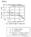
- a time constant ⁇ for a luminance rise of the cold cathode fluorescent tube satisfies a relation ⁇ -0.0006T 3 +0.0288T 2 -0.4668T+26.8 at an ambient temperature T (°C) upon start-up of the cold cathode fluorescent tube ranging from -10°C to +25°C.
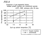
- a pre-exponential factor A of a luminance rising characteristic of the cold cathode fluorescent tube satisfies a relation A ⁇ 0.92T+60 within the start-up ambient temperature range, the pre-exponential factor A being represented as a percentage with respect to a pre-exponential factor A0 of saturation relative luminance.
- the activation energy of the pre-exponential factor of the cold cathode fluorescent tube is about 3.0 kcal/mol or less within the start-up ambient temperature range.
- about 95% or more of a total surface area of the fluorescent section of the cold cathode fluorescent tube is exposed to air, and about 50% or more of light emitted from the cold cathode fluorescent tube is utilized for illumination.
- the illumination device further includes a polarization selective reflection sheet provided on a light-emitting side of the cold cathode fluorescent tube.
- a constant current is applied to the cold cathode fluorescent tube during operation of the illumination device.
- the illumination device further includes a temperature detector for detecting an ambient temperature of the cold cathode fluorescent tube; and an operation apparatus for setting a prescribed current applied to the cold cathode fluorescent tube, based on the temperature detected by the temperature detector.
- the current applied to the cold cathode fluorescent tube is controlled based on an ambient temperature upon start-up of the cold cathode fluorescent tube.
- a method for driving an illumination device includes the steps of detecting an ambient temperature of the cold cathode fluorescent tube by the temperature detector; setting a prescribed current applied to the cold cathode fluorescent tube, based on the temperature detected by the temperature detector; and thereby controlling the current applied to the cold cathode fluorescent tube, based on an ambient temperature upon start-up of the cold cathode fluorescent tube.
- a display device includes an illumination device according to the one aspect of the present invention, and a transmission-type display element for receiving light emitted from the illumination device.
- the transmission-type display element is a liquid crystal display device.
- an illumination device including a cold cathode fluorescent tube includes a temperature sensor thermally coupled to the cold cathode fluorescent tube, wherein luminance is adjusted by controlling power supplied to the cold cathode fluorescent tube based on a sensed-temperature signal from the temperature sensor.
- the temperature sensor is provided at a portion of a wall of the cold cathode fluorescent tube.
- the wall is a wall located in a direction outward within the illumination device.
- the temperature sensor is provided at a corner of a display plane.
- luminance is adjusted by approximating a relation between luminance and a temperature sensed by the temperature sensor by one of expressions of a first order which are provided for respective temperature ranges, and controlling a duty ratio of the power supplied to the cold cathode fluorescent tube based on the expression.
- luminance is adjusted by approximating a relation between luminance and a temperature sensed by the temperature sensor by a polynomial, and controlling a duty ratio of the power supplied to the cold cathode fluorescent tube based on the polynomial.
- a larger amount of power is supplied to the cold cathode fluorescent tube upon start-up than during a normal operation.
- a heat capacity of the cold cathode fluorescent tube is reduced by decreasing a diameter of the cold cathode fluorescent tube as much as possible or by decreasing a size of the cold cathode fluorescent tube as much as possible.
- a display device uses an illumination device according to the yet another aspect of the present invention.
- the illumination device includes a temperature sensor thermally coupled to the cold cathode fluorescent tube, wherein luminance is adjusted by controlling power supplied to the cold cathode fluorescent tube based on a sensed-temperature signal from the temperature sensor.
- a method for driving an illumination device includes the steps of sensing a temperature of the cold cathode fluorescent tube, and controlling power supplied to the cold cathode fluorescent tube, based on the sensed temperature, thereby adjusting luminance.
- a cold cathode fluorescent tube included in an illumination device of the present invention has a heat capacity smaller than that of a conventional cold cathode fluorescent lamp. Energy applied to the cold cathode fluorescent tube is not only used for light emission but is released as heat. Accordingly, a smaller heat capacity of the cold cathode fluorescent tube has an advantage that the cold cathode fluorescent tube can be rapidly heated by using heat generated from the cold cathode fluorescent tube itself.
- the cold cathode fluorescent tube included in the illumination device of the present invention generates more heat than the conventional cold cathode fluorescent tube, and therefore, the cold cathode fluorescent tube can be heated rapidly.
- the illumination device of the present invention includes a polarization selective reflection sheet, and therefore, the illumination device can efficiently utilize light, emitted from the cold cathode fluorescent tube, for illumination.
- the illumination device of the present invention has such a structure that power supplied to the cold cathode fluorescent tube is controlled by a temperature sensed by a temperature sensor which is thermally coupled to the cold cathode fluorescent tube. Therefore, intended brightness can be obtained at any ambient temperature.
- thermally coupled herein means that the temperature sensor is provided at such a position that the temperature sensor is approximately in thermal equilibrium with the cold cathode fluorescent tube.
- the reason for this is as follows.
- the cold cathode fluorescent tube used as a light source is affected by an ambient temperature.
- a parameter which determines brightness of the cold cathode fluorescent tube that is, luminance of the cold cathode fluorescent tube depends on the vapor pressure of mercury filling the cold cathode fluorescent tube. Therefore, the brightness will be a function of only an equilibrium temperature.
- This power control is realized as follows.
- a relation between a temperature sensed by a temperature sensor and intended luminance is approximated by one of expressions of the first order which are provided for respective prescribed temperature ranges, and thereafter, a duty ratio of power supplied to the cold cathode fluorescent tube is controlled for achieving the intended luminance, based on the approximation expression of the first order.
- a relation between a temperature sensed by the temperature sensor and intended luminance is approximated by a polynomial, and thereafter, a duty ratio of power supplied to the cold cathode fluorescent tube is controlled for achieving the intended luminance, based on the polynomial approximation.
- the illumination device is structured such that a larger amount of power supplied to the cold cathode fluorescent tube upon start-up than during a normal operation, a start-up characteristic of the cold cathode fluorescent tube can be improved. As a result, intended luminance can be achieved rapidly.
- Thermal equilibrium is not achieved right after the start-up.
- a heat capacity of the cold cathode fluorescent tube will be reduced. Therefore, the difference between an actual temperature within the cold cathode fluorescent tube and a temperature sensed by the temperature sensor is decreased. As a result, intended brightness can be obtained rapidly by controlling power supplied to the cold cathode fluorescent tube according to the sensed temperature.
- the cold cathode fluorescent tube can be heated rapidly. As a result, intended brightness can be obtained rapidly.
- the temperature sensor does not need to be provided over the whole surface of the cold cathode fluorescent tube.
- the temperature sensor only needs to be provided at a portion of the cold cathode fluorescent tube. With such a structure, luminous flux can be effectively utilized.
- FIG. 1A is a schematic diagram showing the display device 100 , and the display device 100 includes an illumination device 110 and a transmission-type display element (for example, a liquid crystal display element) 8 .
- a transmission-type display element for example, a liquid crystal display element
- FIG. 1B is a cross sectional view taken along the line 1B-1B of Figure 1A , showing the illumination device 110 included in the display device 100 .
- the illumination device 110 includes a cold cathode fluorescent tube 1 with a small heat capacity and large heat generation, which will be described later, a reflection sheet 2 , a light guiding element 3 , a diffusion sheet 4 , a prism sheet 5 (for example, a BEF sheet made by 3M inc.), a polarization selective reflection sheet 6 , and a diffusion sheet 7 .
- the illumination device 110 of the present invention is different from a conventional illumination device in that the illumination device 110 of the present invention has the cold cathode fluorescent tube 1 with a small heat capacity and large heat generation and also has the polarization selective reflection sheet 6 .
- the cold cathode fluorescent tube 1 with a small heat capacity and large heat generation herein refers to a cold cathode fluorescent tube which has a smaller heat capacity as well as generates a larger amount of heat as compared to the conventional cold cathode fluorescent tube.
- a small heat capacity and large heat generation can be effectively utilized.
- the illumination device 110 More preferably, about 98% of the total surface area is exposed to air. It is also preferable, in view of efficiency to structure the illumination device 110 , that about 50% or more of light from the cold cathode fluorescent tube 1 is guided by the light-guiding element 3 to be used for illumination. A position of the cold cathode fluorescent tube 1 is determined in consideration of both the light utilization efficiency and the thermal isolation.
- the polarization selective reflection sheet 6 may be located between the diffusion sheet 4 and the prism sheet 5 , and that the diffusion sheet 7 may be omitted.
- the polarization selective reflection sheet 6 may also be omitted as required according to applications. In the case where a display element utilizing only specific linearly polarized light, such as a liquid crystal display element, is used, luminance can be improved by using the polarization selective reflection sheet 6 .
- the illumination device and the display device according to the present invention are not limited to the structure described above. As can be seen from the following description, the components having respective individual features can be separately used as appropriate according to applications.
- the illumination device includes a cold cathode fluorescent tube having a small heat capacity.
- a cold cathode fluorescent tube prevents heat energy generated within the cold cathode fluorescent tube from being released outside itself, whereby the cold cathode fluorescent tube itself can be heated rapidly.
- heat energy released from the cold cathode fluorescent tube is not utilized effectively for heating the cold cathode fluorescent tube itself. This is because the heat is absorbed by a glass tube forming the cold cathode fluorescent tube and propagated within the glass tube. Such absorption and propagation of the heat occurs because a heat capacity of the glass tube forming the conventional cold cathode fluorescent tube is too large with respect to the amount of heat generated by the cold cathode fluorescent tube.
- the cold cathode fluorescent tube according to the present invention is a cold cathode fluorescent tube having a heat capacity C of about 0.035 Wsec/°C or less per unit length (1 cm) of the glass tube, the heat capacity C being defined by the following expression (1).
- the cold cathode fluorescent tube wherein the glass tube has an inner diameter da of about 0.20 cm or less is preferred.
- C 4.2 ⁇ ( ⁇ /4) ⁇ (db 2 -da 2 ) ⁇ s1 ⁇ 1 ⁇
- C represents a heat capacity (Wsec/°C) of the glass tube
- db represents an outer diameter (cm) of the glass tube
- da represents an inner diameter (cm) of the glass tube
- s1 represents specific heat (cal/g ⁇ °C)
- ⁇ 1 represents a density (g/cm 3 ) of a glass material.
- Typical values of the above-mentioned parameters for the glass tube of the cold cathode fluorescent tube used in the present invention and a conventional glass tube are shown in the following Table 1.
- the values shown in Table 1 are those per unit length (1 cm) of the glass tube, while a glass tube wherein a distance between electrodes is 15 cm was used in the experiment.
- the heat capacity C of the cold cathode fluorescent tube according to the present invention has a very small value, that is, about 55% of the heat capacity of the conventional cold cathode fluorescent tube.
- the cold cathode fluorescent tube of the present invention itself is effectively heated upon activation by heat generated by the cold cathode fluorescent tube. Accordingly, the rising characteristic of luminance can be improved.
- a preferred range of the heat capacity of the cold cathode fluorescent tube used in the present invention can also be defined by a simpler expression.
- Dg which is determined by an inner diameter of the glass tube
- Dt cross sectional area of the glass tube of the cold cathode fluorescent tube
- a value of Dt/Dg of the cold cathode fluorescent tube used in the present invention is preferably about 1.0 or less. This relation can be defined generally by the expression Dt/Dg ⁇ 2/da (per 1 mm). Moreover, a smaller surface area of the glass tube is preferred in order to reduce heat energy losses through the surface of the glass tube of the cold cathode fluorescent tube. It is also preferable that the glass tube is not in contact with any other members of the illumination device and is thermally isolated therefrom by air.
- the thermal resistance R of the glass tube is considered.
- a saturation temperature Ts herein indicates a temperature reached when the wall temperature of the cold cathode fluorescent tube attains a steady state.
- the thermal conductivity K can not be obtained from the above-mentioned theoretical expression. Therefore, the thermal conductivity K was obtained based on the above-mentioned experimental expression.
- thermal resistance R was calculated for different values of Vccft, Iccft and T, using the above-mentioned experimental expression of the expression (2).
- Vp was 150 V
- L was 16.5 cm
- T was 25°C.
- a heat dissipation coefficient hw is proportional to an outer diameter db of the glass tube raised to the -1/4th power. Therefore, the thermal conductivity K calculated from the above-mentioned theoretical expression is proportional to the outer diameter db raised to the 3/4th power.
- the thermal conductivity K for the glass tube having an outer diameter db of 0.30 was calculated by multiplying the experimental values for the glass tube having an outer diameter db of 0.26 by a conversion factor 1.113. This result is also shown in the following Table 3.
- the thermal conductivity of the cold cathode fluorescent tube of the present invention is smaller than that of the conventional cold cathode fluorescent tube by 10% or more, and therefore, heat is less likely to be released by the cold cathode fluorescent tube of the present invention.
- the cold cathode fluorescent tube of the present invention itself can be heated more efficiently than the conventional cold cathode fluorescent tube when both fluorescent tubes generate the same amount of heat.
- a time constant of the rise of luminance of the cold cathode fluorescent tube is considered.
- a time constant ⁇ s of the luminance rise per unit length (1 cm) of the glass tube is given by the following expression (3) using a heat capacity C and heat resistance R per unit length (1 cm) of the glass tube.
- This time constant is determined by a structure of the cold cathode fluorescent tube, and therefore, is herein specifically referred to as a structure-factor time constant ⁇ s.
- ⁇ s C ⁇ R
- the values R in Table 4 were obtained from the values K in the above Table 3.
- the time constant ⁇ s of the cold cathode fluorescent tube of the present invention is very short as compared to that of the conventional example, and therefore, the cold cathode fluorescent tube of the present invention can be heated more easily.
- a time constant ⁇ s of a cold cathode fluorescent tube which is preferably used in the present invention is preferably about 11 seconds or less.
- the cold cathode fluorescent tube of the present invention has a shorter time constant ⁇ than that of the conventional example, and therefore, the cold cathode fluorescent tube of the present invention is heated faster than that of the conventional example.
- a time constant ⁇ s can be used for relative evaluation of the rising characteristics of luminance of the cold cathode fluorescent tubes.
- the values ⁇ s shown in the above Table 4 are different from the values ⁇ in Table 5, an actual time constant of the rise of luminance can not be correctly evaluated only by a structure of a cold cathode fluorescent tube.
- a range of time constants ⁇ used preferably in the cold cathode fluorescent tube of the present invention were obtained. Measured values were approximated by a polynomial of the third order (curve fitting). Then, a boundary curve of the preferred time constants ⁇ was obtained based on the curve obtained by the curve fitting. The boundary curve is shown in Figure 2 . Values ⁇ included in the region on and below the boundary curve (i.e., ⁇ 0.0006T 3 + 0.0288T 2 - 0.4668T + 26.8 , where T represents an ambient temperature (°C)) are preferred.
- A0 represents a pre-exponential factor of saturation relative luminance
- ⁇ E represents activation energy (kcal/mol)
- kb represents a Boltzmann's constant
- T represents an ambient temperature (°C) upon start-up of the cold cathode fluorescent tube.
- the activation energy of the cold cathode fluorescent tube of the present invention is very small as compared to the cold cathode fluorescent tube of the conventional example, and therefore, the cold cathode fluorescent tube of the present invention has a stable thermal characteristic over a broad range of temperatures.
- the activation energy of the cold cathode fluorescent tube used preferably in the present invention is preferably about 3.0 kcal/mol or less at an ambient temperature in the range from -10°C to +25°C.
- the pre-exponential factor A is preferably A ⁇ 0.92T + 60 at a temperature in the range from -10°C to +25°C.
- An illumination device using a cold cathode fluorescent tube generating a larger amount of heat than the conventional cold cathode fluorescent tube would solve the conventional problem of an insufficient luminance rise at a low temperature.
- the cold cathode fluorescent tube generates a larger amount of heat
- mercury within the cold cathode fluorescent tube is heated, whereby the amount of mercury vapor will be significantly increased.
- luminance of the illumination device will be increased.
- the first method is to use a higher gas pressure in the cold cathode fluorescent tube than that in the conventional example.
- the second method is to increase a ratio of an argon gas in a gas filling the cold cathode fluorescent tube.
- the amount of heat generation by the cold cathode fluorescent tube is increased.
- the reason for this is as follows.
- a gas pressure in the cold cathode fluorescent tube is increased, a mean free path for ionized atoms traveling within the cold cathode fluorescent tube is reduced, and therefore, the number of collisions between the atoms is larger than that in the conventional cold cathode fluorescent tube.
- the gas pressure is preferably about 100 Torr or more, and more preferably, about 120 Torr or more.
- the amount of heat generation by the cold cathode fluorescent tube is increased.
- the cold cathode fluorescent tube is filled with a mixed gas of neon and argon. Since an argon gas is about twice as heavy as a neon gas in terms of an atomic weight, the amount of heat generated upon collision of an argon gas is larger than that generated upon collision of an neon gas. Accordingly, the amount of heat generation by the cold cathode fluorescent tube can be increased by increasing the ratio of an argon gas.
- the argon/neon ratio is set to about 40/60 or more so as to increase the amount of heat generated by the cold cathode fluorescent tube.
- a gas pressure of the cold cathode fluorescent tube is 120 Torr, and the argon/neon ratio is about 40/60.
- a gas pressure of the cold cathode fluorescent tube is 60 Torr and the argon/neon ratio is 5/95.
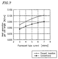
- the amount of heat generated by the cold cathode fluorescent tube (per unit length and per unit volume) is larger than that generated by the conventional cold cathode fluorescent tube.
- the cold cathode fluorescent tube used preferably in the present invention satisfy the relation Wv/Iccft ⁇ 0.5, where Wv(W) represents the amount of heat generation per unit volume and Iccft (mA) represents a current across the cold cathode fluorescent tube. This corresponds to a region on and above the straight line in Figure 8 .
- Figure 9 shows a relation between a current and a voltage across the cold cathode fluorescent tube for the respective cold cathode fluorescent tubes of the present invention and the conventional example.
- a voltage applied to the cold cathode fluorescent tube of the present invention is higher than that in the conventional example.
- Figure 10 shows power consumption of the respective cold cathode fluorescent tubes of the present invention and the conventional example.
- the power consumption of the cold cathode fluorescent tube of the present invention is larger than that of the conventional example.
- the cold cathode fluorescent tube consumes a large amount of power at a positive column. Therefore, it can be found that the amount of heat generated by a gas at the fluorescent section of the cold cathode fluorescent tube of the present invention is larger than that in the case of the conventional example.
- the cold cathode fluorescent tube according to the present invention has an excellent luminance rising characteristic. Therefore, it is not necessary to apply a boost current upon activation at a low temperature. However, it should be understood that the luminance rising characteristic at a low temperature can be improved by applying a boost current upon activation at a low temperature.
- a boost current is also applied upon activation.
- An operation mode is selected by, for example, an ambient temperature of the on-vehicle display device.
- a current higher than a rated current for example, 4 mArms
- a current of 5 mArms is applied to the cold cathode fluorescent tube for a short time from activation.
- the ambient temperature is equal to or higher than the above-mentioned temperature range, it is sufficient to apply the rated current to the cold cathode fluorescent tube from the activation.
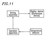
- such selection of the operation mode is carried out according to the flow chart shown in Figure 12 by a control circuit system shown in Figure 11 .
- a temperature detector provided in the vicinity of the display device measures an ambient temperature.
- an operation apparatus receives the ambient temperature, determines current setting for the cold cathode fluorescent tube, and thereafter applies a signal to a driving apparatus so as to apply a rated current or a boost current.
- the driving apparatus starts operating to apply a prescribed current for the cold cathode fluorescent tube to the illumination device.
- a polarization direction of light emitted from the illumination device can be changed to an optimal polarization direction for the display device to increase efficiency of utilizing light.
- the first method is to use a polarization selective reflection sheet for reflecting an S-polarized light component while transmitting a P-polarized light component.
- a structure of such a polarization selective reflection sheet is disclosed in detail in Japanese Laid-Open Publication No. 6-51399.
- the second method is to use a ⁇ /4 plate and a polarization selective reflection sheet for reflecting a left circularly-polarized light component while transmitting a right circularly-polarized light component.
- a polarization selective reflection sheet and a ⁇ /4 plate are disclosed in detail in the United States Patent No. 5506704.
- the display device provided on the illumination device is a device utilizing polarized light (for example, a liquid crystal display device).
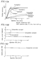
- FIG. 13A A luminance rising characteristic at an ambient temperature of about -30°C is shown in Figure 13A as an example 1.
- an illumination device has the same structure as that shown in Figure 1B except for not using a polarization selective reflection sheet 6 , and includes a display element which utilizes polarized light for display.
- a constant current of about 4.5 mArms was applied to a cold cathode fluorescent tube with a small heat capacity and large heat generation, as shown in the following Table 9 and Figure 13B .
- Table 9 A current applied to respective cold cathode fluorescent tubes of examples and comparative examples, and presence/absence of a polarization selective reflection sheet in the respective cold cathode fluorescent tubes, are shown in the following Table 9.
- FIG. 13A A luminance rising characteristic at an ambient temperature of about -30°C is shown in Figure 13A as an example 2.
- an illumination device has the same structure as that of the example 1 except for using a polarization selective reflection sheet 6 utilizing linearly polarized light, and includes a display element which utilizes polarized light for display.
- a constant current of about 4.5 mArms was applied to a cold cathode fluorescent tube with a small heat capacity and large heat generation, as shown in the following Table 9 and Figure 13B .
- FIG. 13A A luminance rising characteristic at an ambient temperature of about -30°C is shown in Figure 13A as an example 3.
- an illumination device has the same structure as that of the example 2 except for using a polarization selective reflection sheet which utilizes circularly polarized light instead of the polarization selective reflection sheet 6 , and includes a display element which utilizes polarized light for display.
- a constant current of about 4.5 mArms was applied to a cold cathode fluorescent tube with a small heat capacity and large heat generation, as shown in the following Table 9 and Figure 13B .
- a luminance rising characteristic at an ambient temperature of about -30°C is shown in Figure 13A as an example 4.
- a slightly larger current of about 6.0 mArms was applied to the cold cathode fluorescent tube of the illumination device of the example 1 for a period of less than about 1 minute from the start-up, and a reduced current of about 4.5 mArms was applied thereafter, as shown in the following Table 9 and Figure 13B .
- a luminance rising characteristic at an ambient temperature of about -30°C is shown in Figure 13A as an example 5.
- a slightly larger current of about 6.0 mArms was applied to the cold cathode fluorescent tube of the illumination device of the example 2 for a period of less than about 1 minute from the start-up, and a reduced current of about 4.5 mArms was applied thereafter, as shown in the following Table 9 and Figure 13B .
- a luminance rising characteristic at an ambient temperature of about -30°C is shown in Figure 13A as an example 6.
- a slightly larger current of about 6.0 mArms was applied to the cold cathode fluorescent tube of the illumination device of the example 3 for a period of less than about 1 minute from the start-up, and a reduced current of about 4.5 mArms was applied thereafter, as shown in the following Table 9 and Figure 13B .
- FIG. 13A A luminance rising characteristic at an ambient temperature of about -30°C is shown in Figure 13A as a comparative example 1.
- an illumination device has the same structure as that shown in Figures 1A and 1B .
- the illumination device of the comparative example 1 do not use the polarization selective reflection sheet 6 of Figure 1B , and includes a conventional cold cathode fluorescent tube.
- a current of about 9.0 mArms which is larger than a rated current of about 7.0 mArms, was applied to the cold cathode fluorescent tube for about 1 minute from the start-up, and a reduced current of about 4.5 mArms was applied thereafter, as shown in the following Table 9 and Figure 13B .
- FIG. 13A A luminance rising characteristic at an ambient temperature of about -30°C is shown in Figure 13A as a comparative example 2.
- an illumination device has the same structure as that shown in Figures 1A and 1B .
- the illumination device do not use the polarization selective reflection sheet 6 of Figure 1B , a conventional cold cathode fluorescent tube is provided, and a heater is provided directly to the cold cathode fluorescent tube.
- a constant current of about 7.0 mArms was applied to the cold cathode fluorescent tube and power of about 5W was supplied to the heater, as shown in the following Table 9 and Figures 13B and 13C .
- each of the above-described examples of the present invention has a significantly improved luminance rising characteristic over the conventional examples.
- luminance variation is within about -25%, achieving a highly stable luminance rising characteristic.
- luminance variation herein indicates a rate at which the luminance is reduced upon switching from a boost current to a rated current. This luminance variation can be given by the expression ⁇ (Bn/Bb) - 1 ⁇ 100 (%) where Bn represents luminance obtained upon switching from a boost current to a rated current, and Bb represents luminance obtained upon completion of a boost current.
- a display device which uses an illumination device including a cold cathode fluorescent tube with a small heat capacity and large heat generation and a polarization selective reflection sheet as described in the first embodiment of the present invention has a superior luminance rise at a low temperature to that of an illumination device including a heater.
- an illumination device of the present invention can solve the problem of an insufficient luminance rise at a low temperature.
- Such an illumination device of the present invention is also advantageous in terms of the safety because a heater is not used.
- no circuit associated with the heater is required. Therefore, the manufacturing cost can be significantly reduced.
- the cost for attaching the heater is not required.
- a current applied to the cold cathode fluorescent tube of the present invention is smaller. Therefore, according to the present invention, power consumption can be reduced as well as a life of the cold cathode fluorescent tube can be increased.
- a luminance rising characteristic at a low temperature which is an essential objective of the present invention, is significantly improved over the above-mentioned case where a large current is applied to the cold cathode fluorescent tube for a while after the start-up.
- An illumination device 120 shown in Figure 1C further includes a temperature sensor 9 thermally coupled to a cold cathode fluorescent tube 1 , in addition to the components of the illumination device 110 shown in Figure 1B .
- the temperature sensor 9 includes a thermistor and is thermally coupled only to one cold cathode fluorescent tube 1 .
- the phrase "thermally coupled" as used herein means that the temperature sensor 9 is provided at such a position that the temperature sensor 9 and the cold cathode fluorescent tube 1 are approximately in thermal equilibrium. More specifically, in the second embodiment, the temperature sensor 9 is provided at a portion of a wall of the cold cathode fluorescent tube 1 . Note that like elements are denoted with like reference numerals in Figures 1B and 1C .
- the temperature sensor 9 may be provided at any position of the walls of the cold cathode fluorescent tube 1 , the temperature sensor 9 is provided at a wall of the cold cathode fluorescent tube 1 , which is located in a direction outward within the display device 101 and the illumination device 120 , as shown in Figure 1C . Such a position is selected because luminous flux from the cold cathode fluorescent tube 1 can be efficiently utilized.
- the temperature sensor 9 may be provided at a position where provision of the temperature sensor 9 is easily accomplished.
- the cold cathode fluorescent tube 1 is affected by an ambient temperature.
- a parameter which determines brightness of the cold cathode fluorescent tube 1 is determined by a vapor pressure of mercury filling the cold cathode fluorescent tube 1 . Therefore, the brightness is a function of an equilibrium temperature (i.e., a temperature of the cold cathode fluorescent tube 1 ).
- the illumination device of the present embodiment controls power supplied to the cold cathode fluorescent tube 1 according to a temperature sensed by the temperature sensor 9 so as to obtain intended brightness, that is, intended luminance at any ambient temperature.
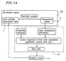
- a control apparatus 10 reads a sensed-temperature signal supplied from the temperature sensor 9 at a prescribed sampling pitch to obtain lamp temperature information. Then, based on the lamp temperature information, prescribed-luminance information, and approximation expressions including an expression of the first order or a polynomial stored in a random access memory (RAM), a relation between a temperature of a wall of the cold cathode fluorescent tube 1 and luminance is obtained for each supplied power. Thus, supplied power for realizing this luminance (for example, a duty ratio) is obtained.
- luminance is a function of a temperature of a wall of the cold cathode fluorescent tube 1 , that is, a function of a temperature sensed by the temperature sensor 9 thermally coupled to the cold cathode fluorescent tube 1 . Therefore, using an expression of the first order or a polynomial for approximation, power supplied to the cold cathode fluorescent tube 1, that is, a duty ratio for achieving intended luminance can be obtained. Then, based on the duty ratio, an inverter circuit 11 connected to each of the cold cathode fluorescent tubes 1 and 1 is driven, whereby intended luminance can be obtained at any ambient temperature.
- luminance BP at a panel plane of the liquid crystal display device 8 is given by the following expression (6) using a temperature TL of a wall of the cold cathode fluorescent tube 1 .
- BP -3 ⁇ 10 -8 TL 6 -4 ⁇ 10 -7 TL 5 +8 ⁇ 10 -5 TL 4 +0.002TL 3 -0.0006TL 2 +0.101TL+29.883
- the luminance BP is given by the following expressions (7) through (9) according to a value of TL.
- BP 10TL-150
- the coefficient in the above expressions (6) through (9) is determined by a heat capacity of the system, luminous flux efficiency of the system, and the like.
- a heat capacity C is preferably about 0.06 Wsec/°C or less, and more preferably, about 0.035 Wsec/°C or less. The reason for this is as follows. The smaller a heat capacity of the cold cathode fluorescent tube 1 is, the more the heat energy generated or conducted within the cold cathode fluorescent tube can be utilized efficiently. As a result, the cold cathode fluorescent tube 1 can be heated faster.
- this relation between luminance and a temperature of the wall of the cold cathode fluorescent tube can be obtained at any ambient temperature.
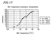
- Figure 18 shows a relation between a temperature TL of the wall of the cold cathode fluorescent tube 1 and luminance at the panel plane of the liquid crystal display element 8 .
- This graph shows the result of the experiment conducted using the respective devices of Figures 1A , 1C and 14 . In this experiment, the above-mentioned expression (6) was used for approximation.
- Figure 19 is a graph showing respective actual luminance values with respect to prescribed luminance values at an ambient temperature ta ranging from -20°C to 45°C.
- luminance values obtained when the control as described above was conducted are shown in comparison with those obtained when no control was conducted.
- a thermistor was used as the temperature sensor 9 .
- luminance close to each of prescribed luminance values 300 [cd/m 2 ], 100 [cd/m 2 ], 47 [cd/m 2 ] and 9 [cd/m 2 ] can be obtained.
- light can be accurately modulated at any ambient temperature.
- approximately constant luminance was obtained for any prescribed luminance at any ambient temperature during operation in the range from 0 to 120 minutes.
- luminance is affected by an ambient temperature and luminance variation is significant for any prescribed luminance.
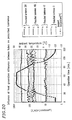
- Figure 20 shows a result of an experiment conducted using the cold cathode fluorescent tubes of different types, that is, two cold cathode fluorescent tubes generating different amounts of heat are used as the cold cathode fluorescent tubes 1 and 1 . It can be seen from Figure 20 that, in this case as well, light can be accurately modulated by conducting the above-mentioned control of the present invention. Note that, in Figure 20 , A represents luminance of a cold cathode fluorescent tube generating a large amount of heat, and B represents luminance of a cold cathode fluorescent tube having a filling-gas pressure which is lower by about 10% of that of the above-mentioned cold cathode fluorescent tube generating a large amount of heat.
- the present invention is not limited to the second embodiment described above.
- the present invention may be structured such that a larger amount of power is supplied to the cold cathode fluorescent tube 1 upon start-up than during a normal operation.
- Such a structure has an advantage that a start-up characteristic of the cold cathode fluorescent tube 1 is improved.
- the illumination device of the second embodiment of the present invention light can be modulated so that intended luminance can be stably achieved at any ambient temperature. Moreover, light modulation can be conducted even when saturation luminance of the cold cathode fluorescent tube has not been obtained, and light modulation can be controlled right after the start-up. Therefore, such an illumination device is particularly preferable when applied to an on-vehicle display device.
- the illumination device of the second embodiment is structured such that a larger amount of power is supplied to the cold cathode fluorescent tube upon start-up than during a normal operation. Therefore, a start-up characteristic of the cold cathode fluorescent tube can be improved, whereby intended luminance can be achieved rapidly.
- a heat capacity of the cold cathode fluorescent tube can be reduced as much as possible and an optimal start-up luminance characteristic can be obtained. Therefore, intended luminance can be achieved rapidly.
- luminous flux from the cold cathode fluorescent tube can be effectively utilized.
Landscapes
- Engineering & Computer Science (AREA)
- Physics & Mathematics (AREA)
- Computer Hardware Design (AREA)
- General Physics & Mathematics (AREA)
- Theoretical Computer Science (AREA)
- Liquid Crystal (AREA)
- Devices For Indicating Variable Information By Combining Individual Elements (AREA)
- Circuit Arrangements For Discharge Lamps (AREA)
Applications Claiming Priority (4)
| Application Number | Priority Date | Filing Date | Title |
|---|---|---|---|
| JP9000995A JPH10199480A (ja) | 1997-01-07 | 1997-01-07 | 照明装置及びそれを備えた表示装置 |
| JP995/97 | 1997-01-07 | ||
| JP9231515A JPH1167485A (ja) | 1997-08-27 | 1997-08-27 | 照明装置及びこの照明装置を備えた表示装置 |
| JP231515/97 | 1997-08-27 |
Publications (3)
| Publication Number | Publication Date |
|---|---|
| EP0852391A2 true EP0852391A2 (de) | 1998-07-08 |
| EP0852391A3 EP0852391A3 (de) | 1998-09-30 |
| EP0852391B1 EP0852391B1 (de) | 2008-08-13 |
Family
ID=26334140
Family Applications (1)
| Application Number | Title | Priority Date | Filing Date |
|---|---|---|---|
| EP97123047A Expired - Lifetime EP0852391B1 (de) | 1997-01-07 | 1997-12-31 | Beleuchtungsvorrichtung, Verfahren zur Steuerung der Beleuchtungsvorrichtung und Anzeige mit solcher Beleuchtungsvorrichtung |
Country Status (4)
| Country | Link |
|---|---|
| US (1) | US6066920A (de) |
| EP (1) | EP0852391B1 (de) |
| KR (2) | KR100355728B1 (de) |
| DE (1) | DE69738899D1 (de) |
Cited By (2)
| Publication number | Priority date | Publication date | Assignee | Title |
|---|---|---|---|---|
| EP1903554A3 (de) * | 2006-09-19 | 2008-12-10 | Funai Electric Co., Ltd. | Flüssigkristallanzeigeeinheit und Flüssigkristallfernsehgerät |
| EP2020655A1 (de) * | 2007-07-25 | 2009-02-04 | Funai Electric Co., Ltd. | Flüssigkristallanzeigevorrichtung und Flüssigkristallfernsehgerät |
Families Citing this family (42)
| Publication number | Priority date | Publication date | Assignee | Title |
|---|---|---|---|---|
| US5910854A (en) | 1993-02-26 | 1999-06-08 | Donnelly Corporation | Electrochromic polymeric solid films, manufacturing electrochromic devices using such solid films, and processes for making such solid films and devices |
| US5668663A (en) | 1994-05-05 | 1997-09-16 | Donnelly Corporation | Electrochromic mirrors and devices |
| US6891563B2 (en) * | 1996-05-22 | 2005-05-10 | Donnelly Corporation | Vehicular vision system |
| US6172613B1 (en) | 1998-02-18 | 2001-01-09 | Donnelly Corporation | Rearview mirror assembly incorporating vehicle information display |
| US6326613B1 (en) | 1998-01-07 | 2001-12-04 | Donnelly Corporation | Vehicle interior mirror assembly adapted for containing a rain sensor |
| US6124886A (en) | 1997-08-25 | 2000-09-26 | Donnelly Corporation | Modular rearview mirror assembly |
| US8294975B2 (en) | 1997-08-25 | 2012-10-23 | Donnelly Corporation | Automotive rearview mirror assembly |
| US8288711B2 (en) | 1998-01-07 | 2012-10-16 | Donnelly Corporation | Interior rearview mirror system with forwardly-viewing camera and a control |
| US6445287B1 (en) | 2000-02-28 | 2002-09-03 | Donnelly Corporation | Tire inflation assistance monitoring system |
| US6477464B2 (en) | 2000-03-09 | 2002-11-05 | Donnelly Corporation | Complete mirror-based global-positioning system (GPS) navigation solution |
| US6693517B2 (en) | 2000-04-21 | 2004-02-17 | Donnelly Corporation | Vehicle mirror assembly communicating wirelessly with vehicle accessories and occupants |
| US6329925B1 (en) | 1999-11-24 | 2001-12-11 | Donnelly Corporation | Rearview mirror assembly with added feature modular display |
| US7370983B2 (en) | 2000-03-02 | 2008-05-13 | Donnelly Corporation | Interior mirror assembly with display |
| WO2001064481A2 (en) | 2000-03-02 | 2001-09-07 | Donnelly Corporation | Video mirror systems incorporating an accessory module |
| US7195381B2 (en) | 2001-01-23 | 2007-03-27 | Donnelly Corporation | Vehicle interior LED lighting system |
| US7167796B2 (en) | 2000-03-09 | 2007-01-23 | Donnelly Corporation | Vehicle navigation system for use with a telematics system |
| JP2002123226A (ja) * | 2000-10-12 | 2002-04-26 | Hitachi Ltd | 液晶表示装置 |
| US7581859B2 (en) | 2005-09-14 | 2009-09-01 | Donnelly Corp. | Display device for exterior rearview mirror |
| US7255451B2 (en) | 2002-09-20 | 2007-08-14 | Donnelly Corporation | Electro-optic mirror cell |
| JP4045097B2 (ja) * | 2001-12-28 | 2008-02-13 | シャープ株式会社 | バックライト装置及びこれを用いた液晶表示装置 |
| US6918674B2 (en) | 2002-05-03 | 2005-07-19 | Donnelly Corporation | Vehicle rearview mirror system |
| WO2003105099A1 (en) | 2002-06-06 | 2003-12-18 | Donnelly Corporation | Interior rearview mirror system with compass |
| US7329013B2 (en) | 2002-06-06 | 2008-02-12 | Donnelly Corporation | Interior rearview mirror system with compass |
| US7274501B2 (en) | 2002-09-20 | 2007-09-25 | Donnelly Corporation | Mirror reflective element assembly |
| US7310177B2 (en) | 2002-09-20 | 2007-12-18 | Donnelly Corporation | Electro-optic reflective element assembly |
| KR100918280B1 (ko) * | 2003-02-17 | 2009-09-18 | 엘지디스플레이 주식회사 | 액정표시장치모듈 |
| US7289037B2 (en) | 2003-05-19 | 2007-10-30 | Donnelly Corporation | Mirror assembly for vehicle |
| KR20050017709A (ko) * | 2003-08-07 | 2005-02-23 | 삼성전자주식회사 | 면광원 장치 및 이를 갖는 액정표시장치 |
| US7446924B2 (en) | 2003-10-02 | 2008-11-04 | Donnelly Corporation | Mirror reflective element assembly including electronic component |
| US7308341B2 (en) | 2003-10-14 | 2007-12-11 | Donnelly Corporation | Vehicle communication system |
| KR101133755B1 (ko) * | 2004-07-22 | 2012-04-09 | 삼성전자주식회사 | 표시 장치 및 표시 장치용 광원의 구동 장치 |
| KR20060104356A (ko) * | 2005-03-30 | 2006-10-09 | 삼성전자주식회사 | 백라이트 어셈블리 및 이를 갖는 액정표시장치 |
| US7414369B2 (en) * | 2005-04-18 | 2008-08-19 | Marvell World Trade Ltd. | Control system for fluorescent light fixture |
| US7560866B2 (en) * | 2005-04-18 | 2009-07-14 | Marvell World Trade Ltd. | Control system for fluorescent light fixture |
| EP1883855B1 (de) | 2005-05-16 | 2011-07-20 | Donnelly Corporation | Fahrzeugspiegelanordnung mit zeichen am reflektierenden teil |
| CN101535087B (zh) | 2005-11-01 | 2013-05-15 | 唐纳利公司 | 具有显示装置的内部后视镜 |
| TW200719054A (en) * | 2005-11-15 | 2007-05-16 | Chi Mei Optoelectronics Corp | Flat panel display and backlight module thereof |
| JP5162120B2 (ja) * | 2006-11-07 | 2013-03-13 | Necディスプレイソリューションズ株式会社 | 表示装置及び輝度制御方法 |
| US8154418B2 (en) | 2008-03-31 | 2012-04-10 | Magna Mirrors Of America, Inc. | Interior rearview mirror system |
| GB0818918D0 (en) * | 2008-10-15 | 2008-11-19 | Icera Inc | Boot algorithm |
| JP5818547B2 (ja) * | 2011-07-15 | 2015-11-18 | キヤノン株式会社 | バックライト装置、その制御方法、及び画像表示装置 |
| CN112037711A (zh) * | 2020-09-11 | 2020-12-04 | 京东方科技集团股份有限公司 | 显示面板的驱动装置及其驱动方法、显示装置 |
Family Cites Families (14)
| Publication number | Priority date | Publication date | Assignee | Title |
|---|---|---|---|---|
| US4029989A (en) * | 1975-09-12 | 1977-06-14 | North American Philips Corporation | Electric discharge lamp with voltage multiplier circuit having a capacitance which changes with temperature |
| JPS5345072A (en) * | 1976-10-04 | 1978-04-22 | Matsushita Electronics Corp | High pressure metal vapor discharge lamp |
| JPS5960880A (ja) * | 1982-09-29 | 1984-04-06 | 日立照明株式会社 | 放電灯点灯装置 |
| JPS6070660A (ja) * | 1983-09-27 | 1985-04-22 | Nippon Denso Co Ltd | 車両用放電管 |
| JPS6174298A (ja) * | 1984-09-19 | 1986-04-16 | 日本電気ホームエレクトロニクス株式会社 | 螢光ランプ点灯装置 |
| JPS63224140A (ja) * | 1987-03-12 | 1988-09-19 | Matsushita Electric Ind Co Ltd | 蛍光灯 |
| JPS6443964A (en) * | 1987-08-10 | 1989-02-16 | Hitachi Ltd | Fluorescent lamp |
| JPH04370649A (ja) * | 1991-06-19 | 1992-12-24 | Toto Ltd | 高輝度放電灯用発光管 |
| JPH05251046A (ja) * | 1992-03-03 | 1993-09-28 | Toshiba Lighting & Technol Corp | 冷陰極けい光ランプ |
| JPH05249432A (ja) * | 1992-03-04 | 1993-09-28 | Sharp Corp | バックライト調光回路 |
| JPH06283142A (ja) * | 1993-03-26 | 1994-10-07 | Toshiba Lighting & Technol Corp | 放電灯及び計器 |
| JPH0743680A (ja) * | 1993-08-03 | 1995-02-14 | Hitachi Ltd | 表示装置 |
| JP3076184B2 (ja) * | 1993-12-22 | 2000-08-14 | 日本電気株式会社 | 液晶表示装置 |
| JPH07211468A (ja) * | 1994-01-18 | 1995-08-11 | Ushio Inc | 小型蛍光管点灯装置 |
-
1997
- 1997-12-30 KR KR1019970079075A patent/KR100355728B1/ko not_active Expired - Fee Related
- 1997-12-31 EP EP97123047A patent/EP0852391B1/de not_active Expired - Lifetime
- 1997-12-31 DE DE69738899T patent/DE69738899D1/de not_active Expired - Lifetime
-
1998
- 1998-01-05 US US09/002,673 patent/US6066920A/en not_active Expired - Lifetime
-
2002
- 2002-04-01 KR KR1020020017877A patent/KR100428920B1/ko not_active Expired - Fee Related
Cited By (2)
| Publication number | Priority date | Publication date | Assignee | Title |
|---|---|---|---|---|
| EP1903554A3 (de) * | 2006-09-19 | 2008-12-10 | Funai Electric Co., Ltd. | Flüssigkristallanzeigeeinheit und Flüssigkristallfernsehgerät |
| EP2020655A1 (de) * | 2007-07-25 | 2009-02-04 | Funai Electric Co., Ltd. | Flüssigkristallanzeigevorrichtung und Flüssigkristallfernsehgerät |
Also Published As
| Publication number | Publication date |
|---|---|
| EP0852391A3 (de) | 1998-09-30 |
| KR100428920B1 (ko) | 2004-04-29 |
| EP0852391B1 (de) | 2008-08-13 |
| US6066920A (en) | 2000-05-23 |
| KR100355728B1 (ko) | 2002-11-18 |
| KR19980070293A (ko) | 1998-10-26 |
| DE69738899D1 (de) | 2008-09-25 |
Similar Documents
| Publication | Publication Date | Title |
|---|---|---|
| US6066920A (en) | Illumination device, method for driving the illumination device and display including the illumination device | |
| KR100360324B1 (ko) | 조명장치 및 표시장치 | |
| US4529912A (en) | Mechanism and method for controlling the temperature and light output of a fluorescent lamp | |
| US20050242693A1 (en) | Optical sheet having a diffusion portion | |
| US5051648A (en) | Flat type low pressure gas discharge lamp | |
| JPH1167485A (ja) | 照明装置及びこの照明装置を備えた表示装置 | |
| US6057635A (en) | Low-pressure mercury vapor-filled discharge lamp, luminaire and display device | |
| JPH0218857A (ja) | 蛍光ランプ装置 | |
| JPH10199480A (ja) | 照明装置及びそれを備えた表示装置 | |
| US7378656B2 (en) | Infrared radiation element and gas sensor using it | |
| JPH09265950A (ja) | 蛍光ランプ、蛍光ランプ装置およびこれを用いた照明装置 | |
| JP2002245829A (ja) | バックライト及び表示装置及びその製造方法 | |
| JP2000315596A (ja) | 照明装置及び表示装置 | |
| JP2000058285A (ja) | 照明装置および表示装置 | |
| JP2002100489A (ja) | 放電ランプ点灯装置およびバックライトユニット | |
| JPH07211468A (ja) | 小型蛍光管点灯装置 | |
| US20040033068A1 (en) | Heating type light source apparatus | |
| JPH10333125A (ja) | 液晶表示装置 | |
| JP2011233525A (ja) | 温度及び電力の関数としてのランプ効率推定による発光量制御技法 | |
| JP2002215058A (ja) | 液晶パネル用バックライト装置 | |
| JP2567127Y2 (ja) | 冷陰極管の温度制御装置 | |
| JP5407452B2 (ja) | 紫外線照射装置 | |
| JP2009032515A (ja) | 照射装置 | |
| JPH04233781A (ja) | 金属蒸気レーザー装置 | |
| JP2000206917A (ja) | バックライト付き液晶表示装置及びこれを含む電子機器 |
Legal Events
| Date | Code | Title | Description |
|---|---|---|---|
| PUAI | Public reference made under article 153(3) epc to a published international application that has entered the european phase |
Free format text: ORIGINAL CODE: 0009012 |
|
| AK | Designated contracting states |
Kind code of ref document: A2 Designated state(s): DE NL |
|
| AX | Request for extension of the european patent |
Free format text: AL;LT;LV;MK;RO;SI |
|
| PUAL | Search report despatched |
Free format text: ORIGINAL CODE: 0009013 |
|
| AK | Designated contracting states |
Kind code of ref document: A3 Designated state(s): AT BE CH DE DK ES FI FR GB GR IE IT LI LU MC NL PT SE |
|
| AX | Request for extension of the european patent |
Free format text: AL;LT;LV;MK;RO;SI |
|
| 17P | Request for examination filed |
Effective date: 19990305 |
|
| AKX | Designation fees paid |
Free format text: DE NL |
|
| 17Q | First examination report despatched |
Effective date: 20020527 |
|
| GRAP | Despatch of communication of intention to grant a patent |
Free format text: ORIGINAL CODE: EPIDOSNIGR1 |
|
| GRAS | Grant fee paid |
Free format text: ORIGINAL CODE: EPIDOSNIGR3 |
|
| GRAA | (expected) grant |
Free format text: ORIGINAL CODE: 0009210 |
|
| AK | Designated contracting states |
Kind code of ref document: B1 Designated state(s): DE NL |
|
| REF | Corresponds to: |
Ref document number: 69738899 Country of ref document: DE Date of ref document: 20080925 Kind code of ref document: P |
|
| PLBE | No opposition filed within time limit |
Free format text: ORIGINAL CODE: 0009261 |
|
| STAA | Information on the status of an ep patent application or granted ep patent |
Free format text: STATUS: NO OPPOSITION FILED WITHIN TIME LIMIT |
|
| 26N | No opposition filed |
Effective date: 20090514 |
|
| PGFP | Annual fee paid to national office [announced via postgrant information from national office to epo] |
Ref country code: NL Payment date: 20121215 Year of fee payment: 16 |
|
| REG | Reference to a national code |
Ref country code: NL Ref legal event code: V1 Effective date: 20140701 |
|
| PG25 | Lapsed in a contracting state [announced via postgrant information from national office to epo] |
Ref country code: NL Free format text: LAPSE BECAUSE OF NON-PAYMENT OF DUE FEES Effective date: 20140701 |
|
| PGFP | Annual fee paid to national office [announced via postgrant information from national office to epo] |
Ref country code: DE Payment date: 20151211 Year of fee payment: 19 |
|
| REG | Reference to a national code |
Ref country code: DE Ref legal event code: R119 Ref document number: 69738899 Country of ref document: DE |
|
| PG25 | Lapsed in a contracting state [announced via postgrant information from national office to epo] |
Ref country code: DE Free format text: LAPSE BECAUSE OF NON-PAYMENT OF DUE FEES Effective date: 20170701 |