EP0851175A1 - Verfahren und Vorrichtung zur Behandlung von Prozessgasen in einer zirkulierenden Wirbelschicht - Google Patents
Verfahren und Vorrichtung zur Behandlung von Prozessgasen in einer zirkulierenden Wirbelschicht Download PDFInfo
- Publication number
- EP0851175A1 EP0851175A1 EP97121573A EP97121573A EP0851175A1 EP 0851175 A1 EP0851175 A1 EP 0851175A1 EP 97121573 A EP97121573 A EP 97121573A EP 97121573 A EP97121573 A EP 97121573A EP 0851175 A1 EP0851175 A1 EP 0851175A1
- Authority
- EP
- European Patent Office
- Prior art keywords
- fluidized bed
- auxiliary gas
- gas flows
- edge zone
- bed reactor
- Prior art date
- Legal status (The legal status is an assumption and is not a legal conclusion. Google has not performed a legal analysis and makes no representation as to the accuracy of the status listed.)
- Granted
Links
- 239000007789 gas Substances 0.000 title claims abstract description 56
- 238000000034 method Methods 0.000 title claims abstract description 48
- 239000007787 solid Substances 0.000 claims abstract description 30
- 239000002245 particle Substances 0.000 claims abstract description 17
- 238000004056 waste incineration Methods 0.000 claims abstract description 3
- 238000005243 fluidization Methods 0.000 claims description 5
- 239000002689 soil Substances 0.000 claims description 4
- 239000003463 adsorbent Substances 0.000 claims description 2
- QVGXLLKOCUKJST-UHFFFAOYSA-N atomic oxygen Chemical compound [O] QVGXLLKOCUKJST-UHFFFAOYSA-N 0.000 claims description 2
- 239000003153 chemical reaction reagent Substances 0.000 claims description 2
- 239000001301 oxygen Substances 0.000 claims description 2
- 229910052760 oxygen Inorganic materials 0.000 claims description 2
- 238000004140 cleaning Methods 0.000 claims 1
- 230000002093 peripheral effect Effects 0.000 claims 1
- 238000009826 distribution Methods 0.000 description 10
- 239000012530 fluid Substances 0.000 description 7
- 238000002485 combustion reaction Methods 0.000 description 5
- UGFAIRIUMAVXCW-UHFFFAOYSA-N Carbon monoxide Chemical compound [O+]#[C-] UGFAIRIUMAVXCW-UHFFFAOYSA-N 0.000 description 3
- 239000002956 ash Substances 0.000 description 3
- 238000001816 cooling Methods 0.000 description 3
- 239000003546 flue gas Substances 0.000 description 3
- 239000010881 fly ash Substances 0.000 description 3
- 239000000463 material Substances 0.000 description 3
- 238000009825 accumulation Methods 0.000 description 2
- 230000007423 decrease Effects 0.000 description 2
- 230000001419 dependent effect Effects 0.000 description 2
- 238000005108 dry cleaning Methods 0.000 description 2
- 238000010791 quenching Methods 0.000 description 2
- 239000007790 solid phase Substances 0.000 description 2
- 239000000725 suspension Substances 0.000 description 2
- 238000005054 agglomeration Methods 0.000 description 1
- 230000002776 aggregation Effects 0.000 description 1
- 238000006243 chemical reaction Methods 0.000 description 1
- 239000000567 combustion gas Substances 0.000 description 1
- 239000000470 constituent Substances 0.000 description 1
- 238000010276 construction Methods 0.000 description 1
- 230000003247 decreasing effect Effects 0.000 description 1
- 230000000694 effects Effects 0.000 description 1
- 239000000446 fuel Substances 0.000 description 1
- 239000003517 fume Substances 0.000 description 1
- 230000005484 gravity Effects 0.000 description 1
- 238000011065 in-situ storage Methods 0.000 description 1
- 238000005457 optimization Methods 0.000 description 1
- 238000004886 process control Methods 0.000 description 1
- 230000010349 pulsation Effects 0.000 description 1
- 230000000171 quenching effect Effects 0.000 description 1
- 239000004576 sand Substances 0.000 description 1
Images
Classifications
-
- F—MECHANICAL ENGINEERING; LIGHTING; HEATING; WEAPONS; BLASTING
- F27—FURNACES; KILNS; OVENS; RETORTS
- F27B—FURNACES, KILNS, OVENS OR RETORTS IN GENERAL; OPEN SINTERING OR LIKE APPARATUS
- F27B15/00—Fluidised-bed furnaces; Other furnaces using or treating finely-divided materials in dispersion
- F27B15/02—Details, accessories or equipment specially adapted for furnaces of these types
- F27B15/10—Arrangements of air or gas supply devices
-
- F—MECHANICAL ENGINEERING; LIGHTING; HEATING; WEAPONS; BLASTING
- F23—COMBUSTION APPARATUS; COMBUSTION PROCESSES
- F23C—METHODS OR APPARATUS FOR COMBUSTION USING FLUID FUEL OR SOLID FUEL SUSPENDED IN A CARRIER GAS OR AIR
- F23C10/00—Fluidised bed combustion apparatus
- F23C10/18—Details; Accessories
- F23C10/20—Inlets for fluidisation air, e.g. grids; Bottoms
-
- F—MECHANICAL ENGINEERING; LIGHTING; HEATING; WEAPONS; BLASTING
- F23—COMBUSTION APPARATUS; COMBUSTION PROCESSES
- F23G—CREMATION FURNACES; CONSUMING WASTE PRODUCTS BY COMBUSTION
- F23G5/00—Incineration of waste; Incinerator constructions; Details, accessories or control therefor
- F23G5/30—Incineration of waste; Incinerator constructions; Details, accessories or control therefor having a fluidised bed
-
- F—MECHANICAL ENGINEERING; LIGHTING; HEATING; WEAPONS; BLASTING
- F23—COMBUSTION APPARATUS; COMBUSTION PROCESSES
- F23G—CREMATION FURNACES; CONSUMING WASTE PRODUCTS BY COMBUSTION
- F23G7/00—Incinerators or other apparatus for consuming industrial waste, e.g. chemicals
- F23G7/06—Incinerators or other apparatus for consuming industrial waste, e.g. chemicals of waste gases or noxious gases, e.g. exhaust gases
-
- F—MECHANICAL ENGINEERING; LIGHTING; HEATING; WEAPONS; BLASTING
- F23—COMBUSTION APPARATUS; COMBUSTION PROCESSES
- F23J—REMOVAL OR TREATMENT OF COMBUSTION PRODUCTS OR COMBUSTION RESIDUES; FLUES
- F23J15/00—Arrangements of devices for treating smoke or fumes
- F23J15/02—Arrangements of devices for treating smoke or fumes of purifiers, e.g. for removing noxious material
-
- F—MECHANICAL ENGINEERING; LIGHTING; HEATING; WEAPONS; BLASTING
- F23—COMBUSTION APPARATUS; COMBUSTION PROCESSES
- F23J—REMOVAL OR TREATMENT OF COMBUSTION PRODUCTS OR COMBUSTION RESIDUES; FLUES
- F23J15/00—Arrangements of devices for treating smoke or fumes
- F23J15/06—Arrangements of devices for treating smoke or fumes of coolers
-
- F—MECHANICAL ENGINEERING; LIGHTING; HEATING; WEAPONS; BLASTING
- F23—COMBUSTION APPARATUS; COMBUSTION PROCESSES
- F23J—REMOVAL OR TREATMENT OF COMBUSTION PRODUCTS OR COMBUSTION RESIDUES; FLUES
- F23J2215/00—Preventing emissions
- F23J2215/20—Sulfur; Compounds thereof
-
- F—MECHANICAL ENGINEERING; LIGHTING; HEATING; WEAPONS; BLASTING
- F23—COMBUSTION APPARATUS; COMBUSTION PROCESSES
- F23J—REMOVAL OR TREATMENT OF COMBUSTION PRODUCTS OR COMBUSTION RESIDUES; FLUES
- F23J2215/00—Preventing emissions
- F23J2215/30—Halogen; Compounds thereof
-
- F—MECHANICAL ENGINEERING; LIGHTING; HEATING; WEAPONS; BLASTING
- F23—COMBUSTION APPARATUS; COMBUSTION PROCESSES
- F23J—REMOVAL OR TREATMENT OF COMBUSTION PRODUCTS OR COMBUSTION RESIDUES; FLUES
- F23J2219/00—Treatment devices
- F23J2219/60—Sorption with dry devices, e.g. beds
Definitions
- the invention relates to a method according to the preamble of claim 1.
- a method of this type is known from DE-A-33 07 848.
- process fumes such as combustion gases containing flammable constituents
- a venturi-like entry device according to the The principle of a circulating fluidized bed works Fluidized bed reactor fed and burned there and cleaned.
- the solid phase by a clear density jump from the one above Gas space is separated during this procedure - i.e. in the circulating fluidized bed - distribution states of the circulating solid without defined Aimed at the boundary layer at which the solids concentration inside the reactor from the bottom up decreases.
- a steady decrease in the solids concentration is desirable from bottom to top within the circulating fluidized bed. So far, this has only been possible with circulating fluidized beds not with venturi-like entry device can be achieved. It has been observed that solid particles down in the edge areas of the fluidized bed sink and settle in the bottom, narrowest area of the bottom Collect the conically tapered fluidized bed reactor. This Solid particles are then circulated at this point and hardly get into circulation anymore. Especially at Treatment of process gases with sticky components, e.g. molten solid such as fly ash solid agglomerations, at this point tennis ball size reachable.
- sticky components e.g. molten solid such as fly ash solid agglomerations
- the accumulation of solids in the lower one The area of the fluidized bed reactor creates a constriction at the entry point in the fluidized bed reactor, whereby the process gas flow is restricted and accelerated becomes. This means there is less time to treat the Process gases available as intended.
- the inhomogeneous Distribution of the solid causes an insufficient Heat exchange and temperature jumps in the reactor.
- Another disadvantage of the known circulating Venturi fluidized bed is that the solids circulation is smaller than with a conventional fluidized bed.
- the present invention is based on the object Process of the type mentioned above and a fluidized bed reactor to carry out the procedure with a steadily decreasing suspension density from bottom to top to create the residue particles. This leads to one improved heat exchange and an even temperature distribution.
- the continuous distribution can be even optimize up to approximately exponential distribution.
- Process gases are understood as industrial gases, in particular those from waste incineration.
- the treatment of such gases according to the invention includes, for example, cooling, dry cleaning (removal of HCl, SO 2, etc.) and / or post-combustion.
- the use of a circulating fluidized bed for cooling (quenching), dry cleaning or afterburning of process gases from a furnace and its advantages are known from the above-mentioned DE-A-33 07 848.
- the process gases are used as fluidizing gases; sand, an adsorbent and / or a reagent, for example, are used as the fluidized bed solid.
- the bed material is preferably formed at least in part from the fly ash originating from the furnace.
- the bed material is distinguished by an excellent heat transfer medium which, with a suitable distribution of solid particles, enables a uniform temperature distribution in the fluidized bed reactor, the temperature being easily controllable in a manner known per se, for example via an external fluid bed cooler.
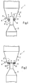
- a fluidized bed reactor 1, 1 ' a fluidized bed reactor 1, 1 ', only the lower part of which is shown in the drawing is a diffuser area that widens conically upwards 2, in which a cylindrical channel 4 for Introducing the process gases to be treated opens.
- the Process gases forming a core jet K flow in the direction of the arrow through the cylindrical channel 4 into the fluidized bed reactor, 1, 1 '.
- the diffuser area 2 forms together with the cylindrical channel 4 and one on these at the bottom adjoining 5 a venturi-like Entry for the process gases.
- the outlet opening is 8 of the cylindrical channel 4 opposite the Bottom edge zone 6 into the interior of the fluidized bed reactor 1 transferred.
- FIG. 2 of a fluidized bed reactor 1 ' is the outlet opening 8 'in the same plane as the bottom edge zone 6.
- Nozzles 9 are used. About the nozzles 9 are in the fluidized bed reactor 1 concentrically and preferably parallel to that emerging from the outlet opening 8 Core jet K a plurality of auxiliary gas flows denoted by arrows H. injected into the fluidized bed reactor 1.
- the auxiliary gas flows about concentric in several circles around the Channel 4 arranged bottom openings 10 'injected, whereby a uniform soil fluidization in the annular Bottom edge zone 6 is reached.
- the auxiliary gas flows both through the nozzles 9th as well as to inject through the bottom openings 10 'at the same time.
- the auxiliary gas flows can either be from an additional Gas or part or all of the process gas be formed.
- At one that takes place in the fluidized bed reactor Afterburning is advantageously an oxygen-containing one Gas, preferably with the auxiliary gas streams H, supplied.
- the invention is further illustrated by the following example illustrated.
- Air was injected into the afterburning chamber of a pilot plant for the afterburning of process gases as auxiliary gas flows over 12 lances with a diameter of 10 mm between 50 and 250 m 3 / h iN (corresponding to an exit speed of 15-75 m / s iN).
- 15 to 50 m 3 / h iN (corresponding to a fluidization rate of 0.08-0.27 m / s iN) were injected with a further auxiliary gas stream for the soil fluidization.
- the amount of flue gas entering the afterburning chamber was 800 to 1400 m 3 / h iN at a temperature of 1200 ° C to 1600 ° C.
- Typical was a flue gas quantity of 1200 m 3 / h iN and 1500 ° C with an auxiliary gas quantity introduced by lances of 150 m 3 / h iN and optionally a further quantity of auxiliary gas for the soil fluidization of 15 m 3 / h iN
- the ratio of the outer diameter of the bottom edge zone 6 to the diameter of the channel 4 or the outlet opening 8 for the core jet is preferably 3: 1 to 10: 8.
- the auxiliary gas streams H swirl the solid particles again loosen up, loosen, hover and promote them into the core jet K without causing deposits and caking comes.
- Any coarse ash can be easily be deducted (the coarse ash deduction is shown in Fig. 1 and 2 with 11, the withdrawal direction with an arrow A).
- the coarse ash deduction enables optimization the pressure drop in the fluidized bed reactor. This will also requires a lower suction power, which is a allows simpler construction of the system.
- a quieter operation due to the method according to the invention achieved by pulsations in the process gas supply is less dependent.
- both the intern as well as the external solids particle circulation increased.
- the good mixing of solid particles with Auxiliary gas flows into the core jet cause a lot good quench effect (e.g. from 1600 ° C to 900 ° C). This is for example, of particular importance for flue gas cooling.
- the aforementioned increase in solid particle circulation also has an increase in the fluid bed cooler extractable for further use Heat energy result.
- the main advantage of the method according to the invention or the fluidized bed reactor according to the invention in bringing about a constant suspension density distribution in the circulating fluidized bed with a venturi-like Infeed and thus optimal process control within the circulating fluidized bed.
Landscapes
- Engineering & Computer Science (AREA)
- Mechanical Engineering (AREA)
- General Engineering & Computer Science (AREA)
- Chemical & Material Sciences (AREA)
- Environmental & Geological Engineering (AREA)
- Dispersion Chemistry (AREA)
- Combustion & Propulsion (AREA)
- Devices And Processes Conducted In The Presence Of Fluids And Solid Particles (AREA)
- Fluidized-Bed Combustion And Resonant Combustion (AREA)
- Crucibles And Fluidized-Bed Furnaces (AREA)
- Treating Waste Gases (AREA)
- Waste-Gas Treatment And Other Accessory Devices For Furnaces (AREA)
Abstract
Description
- Fig. 1
- im vertikalen Mittelschnitt einen unteren Teil eines Wirbelschichtreaktors zum Durchführen des erfindungsgemässen Verfahrens gemäss einem ersten Ausführungsbeispiel und
- Fig. 2
- im vertikalen Mittelschnitt einen unteren Teil eines Wirbelschichtreaktors zum Durchführen des erfindungsgemässen Verfahrens gemäss einem zweiten Ausführungsbeispiel.
Claims (15)
- Verfahren zur Behandlung von Prozessgasen, insbesondere aus der Abfallverbrennung, in einer zirkulierenden Wirbelschicht, wobei die Prozessgase von unten über einen venturidüsenartigen Eintritt in die Wirbelschicht eingeführt werden, dadurch gekennzeichnet, dass die Prozessgase in einem Kernstrahl (K) in die Wirbelschicht eingeführt werden und gleichzeitig in einer ringförmigen Randzone (6), konzentrisch zum Kernstrahl (K), Hilfsgasströme (H) in die zirkulierende Wirbelschicht eingedüst werden, derart, dass in Randbereichen der zirkulierenden Wirbelschicht nach unten sinkende Wirbelschicht-Feststoffpartikel in den Kernstrahl (K) gefördert werden.
- Verfahren nach Anspruch 1, dadurch gekennzeichnet, dass die Hilfsgasströme (H) parallel zum Kernstrahl (K) eingedüst werden.
- Verfahren nach Anspruch 1 oder 2, dadurch gekennzeichnet, dass als Hilfsgas mindestens teilweise das Prozessgas verwendet wird.
- Verfahren nach Anspruch 1 oder 2, dadurch gekennzeichnet, dass als Hilfsgas ein weiteres Gas verwendet wird.
- Verfahren nach einem der Ansprüche 1 bis 4, dadurch gekennzeichnet, dass das Verhältnis des Aussendurchmessers der ringförmigen Randzone (6) zum Durchmesser des Kernstrahles (K) 3:1 bis 10:8 beträgt.
- Verfahren nach einem der Ansprüche 1 bis 5, dadurch gekennzeichnet, dass in der ringförmigen Randzone (6) mittels der Hilfsgasströme (H) eine gleichmässige Bodenfluidisierung erfolgt, wobei die mittlere Geschwindigkeit der Hilfsgasströme (H) über die Bodenfläche der Randzone vorzugsweise 0,05 bis 0,3 m/s, gerechnet bei Normalbedingungen, beträgt.
- Verfahren nach einem der Ansprüche 1 bis 6, dadurch gekennzeichnet, dass ein Teil der Hilfsgasströme (H) mit einer Austrittsgeschwindigkeit von 15 bis 75 m/s, gerechnet bei Normalbedingungen, eingedüst wird.
- Verfahren nach einem der Ansprüche 1 bis 7, dadurch gekennzeichnet, dass zur Durchführung einer Trockengasreinigung Feststoffpartikel, enthaltend ein Reagens und/oder Adsorptionsmittel, in der zirkulierenden Wirbelschicht verwendet werden.
- Verfahren nach einem der Ansprüche 1 bis 7, dadurch gekennzeichnet, dass zum Durchführen einer Nachverbrennung ein sauerstoffhaltiges Gas, vorzugsweise in Form von Hilfsgasströmen (H), eingeführt wird.
- Wirbelschichtreaktor (1, 1') zur Durchführung des Verfahrens nach Anspruch 1, mit einem sich konisch nach oben erweiternden Diffusor-Bereich (2), der zusammen mit einem zylindrischen Kanal (4) und einem Konfusor (5) einen venturidüsenartigen Eintritt für die Prozessgase bildet, dadurch gekennzeichnet, dass zwischen dem Kanal (4) und der Diffusor-Wand (3) eine ringförmige Bodenrandzone (6) vorhanden ist, die eine Mehrzahl von gleichmässig verteilten konzentrisch zum zylindrischen Kanal (4) angeordneten Bodenöffnungen (10, 10') zum Eindüsen der Hilfsgasströme (H) aufweist.
- Wirbelschichtreaktor nach Anspruch 10, dadurch gekennzeichnet, dass mindestens ein Teil der Bodenöffnungen (10) mit Düsen (9) zum Eindüsen der Hilfsgasströme (H) versehen sind.
- Wirbelschichtreaktor nach Anspruch 10 oder 11, dadurch gekennzeichnet, dass die Bodenöffnungen (10') in mehreren zum zylindrischen Kanal (4) konzentrischen Kreisen angeordnet sind.
- Wirbelschichtreaktor nach einem der Ansprüche 10 bis 12, dadurch gekennzeichnet, dass der zylindrische Kanal (4) in den Diffusor-Bereich (2) hineinragt.
- Wirbelschichtreaktor nach einem der Ansprüche 10 bis 12, dadurch gekennzeichnet, dass der zylindrische Kanal (4) diffusorseitig mit der Bodenrandzone (6) fluchtet.
- Wirbelschichtreaktor nach einem der Ansprüche 10 bis 14, dadurch gekennzeichnet, dass oberhalb der Bodenrandzone (6) im unteren Diffusor-Bereich (2) ein Grobaschenabzug (11) angeordnet ist.
Applications Claiming Priority (3)
| Application Number | Priority Date | Filing Date | Title |
|---|---|---|---|
| CH3200/96 | 1996-12-30 | ||
| CH320096 | 1996-12-30 | ||
| CH320096 | 1996-12-30 |
Publications (2)
| Publication Number | Publication Date |
|---|---|
| EP0851175A1 true EP0851175A1 (de) | 1998-07-01 |
| EP0851175B1 EP0851175B1 (de) | 2002-04-17 |
Family
ID=4250827
Family Applications (1)
| Application Number | Title | Priority Date | Filing Date |
|---|---|---|---|
| EP97121573A Expired - Lifetime EP0851175B1 (de) | 1996-12-30 | 1997-12-08 | Verfahren und Vorrichtung zur Behandlung von Prozessgasen in einer zirkulierenden Wirbelschicht |
Country Status (12)
| Country | Link |
|---|---|
| EP (1) | EP0851175B1 (de) |
| JP (1) | JP3082035B2 (de) |
| KR (1) | KR100271123B1 (de) |
| AT (1) | ATE216476T1 (de) |
| CA (1) | CA2222958A1 (de) |
| CZ (1) | CZ293171B6 (de) |
| DE (1) | DE59707042D1 (de) |
| ES (1) | ES2121717T1 (de) |
| HU (1) | HUP9702470A3 (de) |
| NO (1) | NO976155L (de) |
| PL (1) | PL324068A1 (de) |
| TW (1) | TW354363B (de) |
Cited By (1)
| Publication number | Priority date | Publication date | Assignee | Title |
|---|---|---|---|---|
| CN101881458A (zh) * | 2010-07-16 | 2010-11-10 | 李登平 | 用于处理垃圾焚烧废气的燃烧装置 |
Families Citing this family (3)
| Publication number | Priority date | Publication date | Assignee | Title |
|---|---|---|---|---|
| DE102008054038B3 (de) * | 2008-10-30 | 2010-04-29 | Karlsruher Institut für Technologie | Verfahren und Vorrichtung zur Reduzierung von Schadstoffemissionen in Verbrennungsanlagen |
| CN110513705B (zh) * | 2018-05-21 | 2024-03-15 | 安德森热能科技(苏州)有限责任公司 | 一种用于废气焚烧的调节比可调的燃烧器 |
| KR102422089B1 (ko) * | 2019-02-28 | 2022-07-18 | 주식회사 엘지화학 | 유동층 반응기 |
Citations (11)
| Publication number | Priority date | Publication date | Assignee | Title |
|---|---|---|---|---|
| GB1120003A (de) * | 1965-03-10 | 1968-07-17 | United States Atomic Energy Commission | |
| US4065271A (en) * | 1973-09-15 | 1977-12-27 | Metallgesellschaft Aktiengesellschaft | Process of separating hydrogen fluoride from gases |
| US4191544A (en) * | 1978-03-17 | 1980-03-04 | The Babcock & Wilcox Company | Gas cleaning apparatus |
| JPS5568506A (en) * | 1978-11-20 | 1980-05-23 | Babcock Hitachi Kk | Rotating fluidized bed furnace |
| DE3307848A1 (de) | 1983-03-05 | 1984-09-06 | Metallgesellschaft Ag, 6000 Frankfurt | Verfahren zur nachverbrennung und reinigung von prozessabgasen |
| EP0211458A1 (de) * | 1985-07-20 | 1987-02-25 | Rolf Dr. Graf | Verfahren zur Entfernung von Schadstoffen aus Rauchgas |
| EP0355690A2 (de) * | 1988-08-16 | 1990-02-28 | A. Ahlstrom Corporation | Schneller Wirbelschichtreaktor |
| US4934282A (en) | 1988-02-18 | 1990-06-19 | Ishikawajima-Harima Jukogyo Kabushiki Kaisha | Circulating type fluidized bed combustion apparatus |
| FR2644795A1 (fr) * | 1989-03-24 | 1990-09-28 | Inst Francais Du Petrole | Procede et dispositif d'injection de la charge d'hydrocarbures dans un procede de craquage catalytique a l'etat fluide |
| US5422080A (en) * | 1994-03-09 | 1995-06-06 | Tampella Power Corporation | Solids circulation enhancing air distribution grid |
| EP0733400A1 (de) * | 1995-03-21 | 1996-09-25 | GRAF-EPE GmbH | Gaseinlass zum Zuführen von Gas in einen Behälter |
Family Cites Families (1)
| Publication number | Priority date | Publication date | Assignee | Title |
|---|---|---|---|---|
| JP3099530B2 (ja) * | 1992-06-22 | 2000-10-16 | 川崎重工業株式会社 | 噴流層ごみ焼却炉 |
-
1997
- 1997-11-28 CA CA002222958A patent/CA2222958A1/en not_active Abandoned
- 1997-12-08 AT AT97121573T patent/ATE216476T1/de not_active IP Right Cessation
- 1997-12-08 ES ES97121573T patent/ES2121717T1/es active Pending
- 1997-12-08 EP EP97121573A patent/EP0851175B1/de not_active Expired - Lifetime
- 1997-12-08 DE DE59707042T patent/DE59707042D1/de not_active Expired - Fee Related
- 1997-12-12 HU HU9702470A patent/HUP9702470A3/hu unknown
- 1997-12-26 JP JP09359693A patent/JP3082035B2/ja not_active Expired - Lifetime
- 1997-12-26 TW TW086119791A patent/TW354363B/zh active
- 1997-12-29 PL PL97324068A patent/PL324068A1/xx unknown
- 1997-12-29 KR KR1019970076670A patent/KR100271123B1/ko not_active Expired - Fee Related
- 1997-12-30 CZ CZ19974229A patent/CZ293171B6/cs not_active IP Right Cessation
- 1997-12-30 NO NO976155A patent/NO976155L/no unknown
Patent Citations (11)
| Publication number | Priority date | Publication date | Assignee | Title |
|---|---|---|---|---|
| GB1120003A (de) * | 1965-03-10 | 1968-07-17 | United States Atomic Energy Commission | |
| US4065271A (en) * | 1973-09-15 | 1977-12-27 | Metallgesellschaft Aktiengesellschaft | Process of separating hydrogen fluoride from gases |
| US4191544A (en) * | 1978-03-17 | 1980-03-04 | The Babcock & Wilcox Company | Gas cleaning apparatus |
| JPS5568506A (en) * | 1978-11-20 | 1980-05-23 | Babcock Hitachi Kk | Rotating fluidized bed furnace |
| DE3307848A1 (de) | 1983-03-05 | 1984-09-06 | Metallgesellschaft Ag, 6000 Frankfurt | Verfahren zur nachverbrennung und reinigung von prozessabgasen |
| EP0211458A1 (de) * | 1985-07-20 | 1987-02-25 | Rolf Dr. Graf | Verfahren zur Entfernung von Schadstoffen aus Rauchgas |
| US4934282A (en) | 1988-02-18 | 1990-06-19 | Ishikawajima-Harima Jukogyo Kabushiki Kaisha | Circulating type fluidized bed combustion apparatus |
| EP0355690A2 (de) * | 1988-08-16 | 1990-02-28 | A. Ahlstrom Corporation | Schneller Wirbelschichtreaktor |
| FR2644795A1 (fr) * | 1989-03-24 | 1990-09-28 | Inst Francais Du Petrole | Procede et dispositif d'injection de la charge d'hydrocarbures dans un procede de craquage catalytique a l'etat fluide |
| US5422080A (en) * | 1994-03-09 | 1995-06-06 | Tampella Power Corporation | Solids circulation enhancing air distribution grid |
| EP0733400A1 (de) * | 1995-03-21 | 1996-09-25 | GRAF-EPE GmbH | Gaseinlass zum Zuführen von Gas in einen Behälter |
Non-Patent Citations (1)
| Title |
|---|
| PATENT ABSTRACTS OF JAPAN vol. 4, no. 111 (M - 025) 9 August 1980 (1980-08-09) * |
Cited By (2)
| Publication number | Priority date | Publication date | Assignee | Title |
|---|---|---|---|---|
| CN101881458A (zh) * | 2010-07-16 | 2010-11-10 | 李登平 | 用于处理垃圾焚烧废气的燃烧装置 |
| CN101881458B (zh) * | 2010-07-16 | 2012-11-14 | 李登平 | 用于处理垃圾焚烧废气的燃烧装置 |
Also Published As
| Publication number | Publication date |
|---|---|
| PL324068A1 (en) | 1998-07-06 |
| JP3082035B2 (ja) | 2000-08-28 |
| HUP9702470A2 (hu) | 1999-07-28 |
| JPH10206028A (ja) | 1998-08-07 |
| EP0851175B1 (de) | 2002-04-17 |
| ES2121717T1 (es) | 1998-12-16 |
| KR19980064781A (ko) | 1998-10-07 |
| DE59707042D1 (de) | 2002-05-23 |
| CZ293171B6 (cs) | 2004-02-18 |
| NO976155D0 (no) | 1997-12-30 |
| NO976155L (no) | 1998-07-01 |
| ATE216476T1 (de) | 2002-05-15 |
| HUP9702470A3 (en) | 1999-12-28 |
| CZ422997A3 (cs) | 1998-11-11 |
| KR100271123B1 (ko) | 2000-12-01 |
| TW354363B (en) | 1999-03-11 |
| CA2222958A1 (en) | 1998-06-30 |
Similar Documents
| Publication | Publication Date | Title |
|---|---|---|
| AT401419B (de) | Wirbelschichtverfahren zur vergasung und verbrennung von brennstoffen sowie vorrichtung zu seiner durchführung | |
| CH668196A5 (de) | Verfahren und einrichtung zum abkuehlen und entstauben von gasen. | |
| DE69825854T2 (de) | Verfahren und vorrichtung zur kühlung von bypass abgasen vom ofen | |
| EP0229119B1 (de) | Wirbelschichtreaktor | |
| DE10260737B4 (de) | Verfahren und Anlage zur Wärmebehandlung von titanhaltigen Feststoffen | |
| DE1758357A1 (de) | Vorrichtung zum Abschrecken und/oder Waschen von Heissgasen | |
| DE2629508A1 (de) | Verfahren und vorrichtung zur behandlung von schwefelhaltiger kohle | |
| DE3117892A1 (de) | Strahlschicht-granulator | |
| EP0597092B1 (de) | Apparat zur herstellung von granulat | |
| EP0851175B1 (de) | Verfahren und Vorrichtung zur Behandlung von Prozessgasen in einer zirkulierenden Wirbelschicht | |
| DE10260734B4 (de) | Verfahren und Anlage zur Herstellung von Schwelkoks | |
| DE2654980A1 (de) | Verfahren und vorrichtung zur waermebehandlung eines materialbetts | |
| DE19927447B4 (de) | Zuführvorrichtung zum Zuführen einer vorbehandelten Beschickungsmischung in einen Schmelzofen | |
| DE4142814A1 (de) | Auf umlaufmassentechnik basierendes verfahren zum abkuehlen von gasen und beim verfahren verwendbarer umlaufmassenkuehler | |
| EP0430144B1 (de) | Verfahren und Vorrichtung zur Minderung der Stickoxid-Konzentration im Abgasstrom von Verbrennungsprozessen | |
| DE3346536C2 (de) | Vorbrenner für Zementrohmehl | |
| EP0202215A2 (de) | Verfahren und Vorrichtung zur Verbrennung von festen, flüssigen, gasförmigen oder pastösen Brennstoffen in einem Wirbelschichtofen | |
| DE1928902A1 (de) | Verfahren und Einrichtung zum Steuern der Staub- und Rauchabgabe | |
| DE2509352A1 (de) | Verfahren zum mischen feinteiliger materialien und vorrichtung zur durchfuehrung | |
| DE3013645A1 (de) | Verfahren und vorrichtung fuer die zufuehrung von teilchen in eine wirbelschicht | |
| DE3928427A1 (de) | Verfahren und vorrichtung zum reinigen von mit schwermetallen, insbesondere quecksilber, kontaminiertem material | |
| DE60011398T2 (de) | Standrohr-einlass fuer zirkulation von partikelförmigen feststoffen in petrochemischen oder anderen prozessen | |
| DE3875801T2 (de) | Substanzbehandlung. | |
| DE3152041T1 (de) | Method and apparatus for continuously burning particles in air stream in a vertical furnace | |
| DD248109A1 (de) | Vorrichtung zur thermischen behandlung von feinkoernigen stoffen |
Legal Events
| Date | Code | Title | Description |
|---|---|---|---|
| PUAI | Public reference made under article 153(3) epc to a published international application that has entered the european phase |
Free format text: ORIGINAL CODE: 0009012 |
|
| AK | Designated contracting states |
Kind code of ref document: A1 Designated state(s): AT BE CH DE DK ES FI FR GB IT LI LU NL SE |
|
| AX | Request for extension of the european patent |
Free format text: AL;LT;LV;MK;RO;SI |
|
| ITCL | It: translation for ep claims filed |
Representative=s name: BARZANO' E ZANARDO MILANO S.P.A. |
|
| GBC | Gb: translation of claims filed (gb section 78(7)/1977) | ||
| EL | Fr: translation of claims filed | ||
| 17P | Request for examination filed |
Effective date: 19980831 |
|
| TCNL | Nl: translation of patent claims filed | ||
| REG | Reference to a national code |
Ref country code: ES Ref legal event code: BA2A Ref document number: 2121717 Country of ref document: ES Kind code of ref document: T1 |
|
| AKX | Designation fees paid |
Free format text: AT BE CH DE DK ES FI FR GB IT LI LU NL SE |
|
| RBV | Designated contracting states (corrected) |
Designated state(s): AT BE CH DE DK ES FI FR GB IT LI LU NL SE |
|
| 17Q | First examination report despatched |
Effective date: 20000713 |
|
| GRAG | Despatch of communication of intention to grant |
Free format text: ORIGINAL CODE: EPIDOS AGRA |
|
| GRAG | Despatch of communication of intention to grant |
Free format text: ORIGINAL CODE: EPIDOS AGRA |
|
| GRAH | Despatch of communication of intention to grant a patent |
Free format text: ORIGINAL CODE: EPIDOS IGRA |
|
| REG | Reference to a national code |
Ref country code: GB Ref legal event code: IF02 |
|
| GRAH | Despatch of communication of intention to grant a patent |
Free format text: ORIGINAL CODE: EPIDOS IGRA |
|
| GRAA | (expected) grant |
Free format text: ORIGINAL CODE: 0009210 |
|
| AK | Designated contracting states |
Kind code of ref document: B1 Designated state(s): AT BE CH DE DK ES FI FR GB IT LI LU NL SE |
|
| PG25 | Lapsed in a contracting state [announced via postgrant information from national office to epo] |
Ref country code: GB Free format text: LAPSE BECAUSE OF FAILURE TO SUBMIT A TRANSLATION OF THE DESCRIPTION OR TO PAY THE FEE WITHIN THE PRESCRIBED TIME-LIMIT Effective date: 20020417 Ref country code: FI Free format text: LAPSE BECAUSE OF FAILURE TO SUBMIT A TRANSLATION OF THE DESCRIPTION OR TO PAY THE FEE WITHIN THE PRESCRIBED TIME-LIMIT Effective date: 20020417 |
|
| REF | Corresponds to: |
Ref document number: 216476 Country of ref document: AT Date of ref document: 20020515 Kind code of ref document: T |
|
| RIC1 | Information provided on ipc code assigned before grant |
Free format text: 7F 23G 7/06 A, 7F 23G 5/30 B, 7F 23J 15/02 B, 7F 23J 15/06 B, 7F 23C 10/02 B |
|
| REG | Reference to a national code |
Ref country code: CH Ref legal event code: EP |
|
| REG | Reference to a national code |
Ref country code: CH Ref legal event code: NV Representative=s name: PATENTANWAELTE SCHAAD, BALASS, MENZL & PARTNER AG |
|
| REF | Corresponds to: |
Ref document number: 59707042 Country of ref document: DE Date of ref document: 20020523 |
|
| PG25 | Lapsed in a contracting state [announced via postgrant information from national office to epo] |
Ref country code: DK Free format text: LAPSE BECAUSE OF FAILURE TO SUBMIT A TRANSLATION OF THE DESCRIPTION OR TO PAY THE FEE WITHIN THE PRESCRIBED TIME-LIMIT Effective date: 20020717 |
|
| ET | Fr: translation filed | ||
| GBV | Gb: ep patent (uk) treated as always having been void in accordance with gb section 77(7)/1977 [no translation filed] |
Effective date: 20020417 |
|
| PG25 | Lapsed in a contracting state [announced via postgrant information from national office to epo] |
Ref country code: ES Free format text: LAPSE BECAUSE OF FAILURE TO SUBMIT A TRANSLATION OF THE DESCRIPTION OR TO PAY THE FEE WITHIN THE PRESCRIBED TIME-LIMIT Effective date: 20021030 |
|
| PG25 | Lapsed in a contracting state [announced via postgrant information from national office to epo] |
Ref country code: LU Free format text: LAPSE BECAUSE OF NON-PAYMENT OF DUE FEES Effective date: 20021208 Ref country code: AT Free format text: LAPSE BECAUSE OF NON-PAYMENT OF DUE FEES Effective date: 20021208 |
|
| PG25 | Lapsed in a contracting state [announced via postgrant information from national office to epo] |
Ref country code: BE Free format text: LAPSE BECAUSE OF NON-PAYMENT OF DUE FEES Effective date: 20021231 |
|
| PLBE | No opposition filed within time limit |
Free format text: ORIGINAL CODE: 0009261 |
|
| STAA | Information on the status of an ep patent application or granted ep patent |
Free format text: STATUS: NO OPPOSITION FILED WITHIN TIME LIMIT |
|
| 26N | No opposition filed |
Effective date: 20030120 |
|
| BERE | Be: lapsed |
Owner name: *VON ROLL UMWELTTECHNIK A.G. Effective date: 20021231 |
|
| PGFP | Annual fee paid to national office [announced via postgrant information from national office to epo] |
Ref country code: SE Payment date: 20041209 Year of fee payment: 8 |
|
| PGFP | Annual fee paid to national office [announced via postgrant information from national office to epo] |
Ref country code: NL Payment date: 20041210 Year of fee payment: 8 |
|
| PG25 | Lapsed in a contracting state [announced via postgrant information from national office to epo] |
Ref country code: IT Free format text: LAPSE BECAUSE OF NON-PAYMENT OF DUE FEES;WARNING: LAPSES OF ITALIAN PATENTS WITH EFFECTIVE DATE BEFORE 2007 MAY HAVE OCCURRED AT ANY TIME BEFORE 2007. THE CORRECT EFFECTIVE DATE MAY BE DIFFERENT FROM THE ONE RECORDED. Effective date: 20051208 |
|
| PG25 | Lapsed in a contracting state [announced via postgrant information from national office to epo] |
Ref country code: SE Free format text: LAPSE BECAUSE OF NON-PAYMENT OF DUE FEES Effective date: 20051209 |
|
| PG25 | Lapsed in a contracting state [announced via postgrant information from national office to epo] |
Ref country code: NL Free format text: LAPSE BECAUSE OF NON-PAYMENT OF DUE FEES Effective date: 20060701 |
|
| EUG | Se: european patent has lapsed | ||
| NLV4 | Nl: lapsed or anulled due to non-payment of the annual fee |
Effective date: 20060701 |
|
| PGFP | Annual fee paid to national office [announced via postgrant information from national office to epo] |
Ref country code: DE Payment date: 20061218 Year of fee payment: 10 |
|
| PGFP | Annual fee paid to national office [announced via postgrant information from national office to epo] |
Ref country code: CH Payment date: 20061221 Year of fee payment: 10 |
|
| PGFP | Annual fee paid to national office [announced via postgrant information from national office to epo] |
Ref country code: FR Payment date: 20061212 Year of fee payment: 10 |
|
| REG | Reference to a national code |
Ref country code: CH Ref legal event code: PL |
|
| PG25 | Lapsed in a contracting state [announced via postgrant information from national office to epo] |
Ref country code: LI Free format text: LAPSE BECAUSE OF NON-PAYMENT OF DUE FEES Effective date: 20071231 Ref country code: DE Free format text: LAPSE BECAUSE OF NON-PAYMENT OF DUE FEES Effective date: 20080701 Ref country code: CH Free format text: LAPSE BECAUSE OF NON-PAYMENT OF DUE FEES Effective date: 20071231 |
|
| REG | Reference to a national code |
Ref country code: FR Ref legal event code: ST Effective date: 20081020 |
|
| PG25 | Lapsed in a contracting state [announced via postgrant information from national office to epo] |
Ref country code: FR Free format text: LAPSE BECAUSE OF NON-PAYMENT OF DUE FEES Effective date: 20071231 |