EP0851175A1 - Method and apparatus for treating process gases in a circulating fluidised bed - Google Patents
Method and apparatus for treating process gases in a circulating fluidised bed Download PDFInfo
- Publication number
- EP0851175A1 EP0851175A1 EP97121573A EP97121573A EP0851175A1 EP 0851175 A1 EP0851175 A1 EP 0851175A1 EP 97121573 A EP97121573 A EP 97121573A EP 97121573 A EP97121573 A EP 97121573A EP 0851175 A1 EP0851175 A1 EP 0851175A1
- Authority
- EP
- European Patent Office
- Prior art keywords
- fluidized bed
- auxiliary gas
- edge zone
- gas flows
- bed reactor
- Prior art date
- Legal status (The legal status is an assumption and is not a legal conclusion. Google has not performed a legal analysis and makes no representation as to the accuracy of the status listed.)
- Granted
Links
Images
Classifications
-
- F—MECHANICAL ENGINEERING; LIGHTING; HEATING; WEAPONS; BLASTING
- F27—FURNACES; KILNS; OVENS; RETORTS
- F27B—FURNACES, KILNS, OVENS, OR RETORTS IN GENERAL; OPEN SINTERING OR LIKE APPARATUS
- F27B15/00—Fluidised-bed furnaces; Other furnaces using or treating finely-divided materials in dispersion
- F27B15/02—Details, accessories, or equipment peculiar to furnaces of these types
- F27B15/10—Arrangements of air or gas supply devices
-
- F—MECHANICAL ENGINEERING; LIGHTING; HEATING; WEAPONS; BLASTING
- F23—COMBUSTION APPARATUS; COMBUSTION PROCESSES
- F23C—METHODS OR APPARATUS FOR COMBUSTION USING FLUID FUEL OR SOLID FUEL SUSPENDED IN A CARRIER GAS OR AIR
- F23C10/00—Fluidised bed combustion apparatus
- F23C10/18—Details; Accessories
- F23C10/20—Inlets for fluidisation air, e.g. grids; Bottoms
-
- F—MECHANICAL ENGINEERING; LIGHTING; HEATING; WEAPONS; BLASTING
- F23—COMBUSTION APPARATUS; COMBUSTION PROCESSES
- F23G—CREMATION FURNACES; CONSUMING WASTE PRODUCTS BY COMBUSTION
- F23G5/00—Incineration of waste; Incinerator constructions; Details, accessories or control therefor
- F23G5/30—Incineration of waste; Incinerator constructions; Details, accessories or control therefor having a fluidised bed
-
- F—MECHANICAL ENGINEERING; LIGHTING; HEATING; WEAPONS; BLASTING
- F23—COMBUSTION APPARATUS; COMBUSTION PROCESSES
- F23G—CREMATION FURNACES; CONSUMING WASTE PRODUCTS BY COMBUSTION
- F23G7/00—Incinerators or other apparatus for consuming industrial waste, e.g. chemicals
- F23G7/06—Incinerators or other apparatus for consuming industrial waste, e.g. chemicals of waste gases or noxious gases, e.g. exhaust gases
-
- F—MECHANICAL ENGINEERING; LIGHTING; HEATING; WEAPONS; BLASTING
- F23—COMBUSTION APPARATUS; COMBUSTION PROCESSES
- F23J—REMOVAL OR TREATMENT OF COMBUSTION PRODUCTS OR COMBUSTION RESIDUES; FLUES
- F23J15/00—Arrangements of devices for treating smoke or fumes
- F23J15/02—Arrangements of devices for treating smoke or fumes of purifiers, e.g. for removing noxious material
-
- F—MECHANICAL ENGINEERING; LIGHTING; HEATING; WEAPONS; BLASTING
- F23—COMBUSTION APPARATUS; COMBUSTION PROCESSES
- F23J—REMOVAL OR TREATMENT OF COMBUSTION PRODUCTS OR COMBUSTION RESIDUES; FLUES
- F23J15/00—Arrangements of devices for treating smoke or fumes
- F23J15/06—Arrangements of devices for treating smoke or fumes of coolers
-
- F—MECHANICAL ENGINEERING; LIGHTING; HEATING; WEAPONS; BLASTING
- F23—COMBUSTION APPARATUS; COMBUSTION PROCESSES
- F23J—REMOVAL OR TREATMENT OF COMBUSTION PRODUCTS OR COMBUSTION RESIDUES; FLUES
- F23J2215/00—Preventing emissions
- F23J2215/20—Sulfur; Compounds thereof
-
- F—MECHANICAL ENGINEERING; LIGHTING; HEATING; WEAPONS; BLASTING
- F23—COMBUSTION APPARATUS; COMBUSTION PROCESSES
- F23J—REMOVAL OR TREATMENT OF COMBUSTION PRODUCTS OR COMBUSTION RESIDUES; FLUES
- F23J2215/00—Preventing emissions
- F23J2215/30—Halogen; Compounds thereof
-
- F—MECHANICAL ENGINEERING; LIGHTING; HEATING; WEAPONS; BLASTING
- F23—COMBUSTION APPARATUS; COMBUSTION PROCESSES
- F23J—REMOVAL OR TREATMENT OF COMBUSTION PRODUCTS OR COMBUSTION RESIDUES; FLUES
- F23J2219/00—Treatment devices
- F23J2219/60—Sorption with dry devices, e.g. beds
Definitions
- the invention relates to a method according to the preamble of claim 1.
- a method of this type is known from DE-A-33 07 848.
- process fumes such as combustion gases containing flammable constituents
- a venturi-like entry device according to the The principle of a circulating fluidized bed works Fluidized bed reactor fed and burned there and cleaned.
- the solid phase by a clear density jump from the one above Gas space is separated during this procedure - i.e. in the circulating fluidized bed - distribution states of the circulating solid without defined Aimed at the boundary layer at which the solids concentration inside the reactor from the bottom up decreases.
- a steady decrease in the solids concentration is desirable from bottom to top within the circulating fluidized bed. So far, this has only been possible with circulating fluidized beds not with venturi-like entry device can be achieved. It has been observed that solid particles down in the edge areas of the fluidized bed sink and settle in the bottom, narrowest area of the bottom Collect the conically tapered fluidized bed reactor. This Solid particles are then circulated at this point and hardly get into circulation anymore. Especially at Treatment of process gases with sticky components, e.g. molten solid such as fly ash solid agglomerations, at this point tennis ball size reachable.
- sticky components e.g. molten solid such as fly ash solid agglomerations
- the accumulation of solids in the lower one The area of the fluidized bed reactor creates a constriction at the entry point in the fluidized bed reactor, whereby the process gas flow is restricted and accelerated becomes. This means there is less time to treat the Process gases available as intended.
- the inhomogeneous Distribution of the solid causes an insufficient Heat exchange and temperature jumps in the reactor.
- Another disadvantage of the known circulating Venturi fluidized bed is that the solids circulation is smaller than with a conventional fluidized bed.
- the present invention is based on the object Process of the type mentioned above and a fluidized bed reactor to carry out the procedure with a steadily decreasing suspension density from bottom to top to create the residue particles. This leads to one improved heat exchange and an even temperature distribution.
- the continuous distribution can be even optimize up to approximately exponential distribution.
- Process gases are understood as industrial gases, in particular those from waste incineration.
- the treatment of such gases according to the invention includes, for example, cooling, dry cleaning (removal of HCl, SO 2, etc.) and / or post-combustion.
- the use of a circulating fluidized bed for cooling (quenching), dry cleaning or afterburning of process gases from a furnace and its advantages are known from the above-mentioned DE-A-33 07 848.
- the process gases are used as fluidizing gases; sand, an adsorbent and / or a reagent, for example, are used as the fluidized bed solid.
- the bed material is preferably formed at least in part from the fly ash originating from the furnace.
- the bed material is distinguished by an excellent heat transfer medium which, with a suitable distribution of solid particles, enables a uniform temperature distribution in the fluidized bed reactor, the temperature being easily controllable in a manner known per se, for example via an external fluid bed cooler.
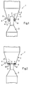
- a fluidized bed reactor 1, 1 ' a fluidized bed reactor 1, 1 ', only the lower part of which is shown in the drawing is a diffuser area that widens conically upwards 2, in which a cylindrical channel 4 for Introducing the process gases to be treated opens.
- the Process gases forming a core jet K flow in the direction of the arrow through the cylindrical channel 4 into the fluidized bed reactor, 1, 1 '.
- the diffuser area 2 forms together with the cylindrical channel 4 and one on these at the bottom adjoining 5 a venturi-like Entry for the process gases.
- the outlet opening is 8 of the cylindrical channel 4 opposite the Bottom edge zone 6 into the interior of the fluidized bed reactor 1 transferred.
- FIG. 2 of a fluidized bed reactor 1 ' is the outlet opening 8 'in the same plane as the bottom edge zone 6.
- Nozzles 9 are used. About the nozzles 9 are in the fluidized bed reactor 1 concentrically and preferably parallel to that emerging from the outlet opening 8 Core jet K a plurality of auxiliary gas flows denoted by arrows H. injected into the fluidized bed reactor 1.
- the auxiliary gas flows about concentric in several circles around the Channel 4 arranged bottom openings 10 'injected, whereby a uniform soil fluidization in the annular Bottom edge zone 6 is reached.
- the auxiliary gas flows both through the nozzles 9th as well as to inject through the bottom openings 10 'at the same time.
- the auxiliary gas flows can either be from an additional Gas or part or all of the process gas be formed.
- At one that takes place in the fluidized bed reactor Afterburning is advantageously an oxygen-containing one Gas, preferably with the auxiliary gas streams H, supplied.
- the invention is further illustrated by the following example illustrated.
- Air was injected into the afterburning chamber of a pilot plant for the afterburning of process gases as auxiliary gas flows over 12 lances with a diameter of 10 mm between 50 and 250 m 3 / h iN (corresponding to an exit speed of 15-75 m / s iN).
- 15 to 50 m 3 / h iN (corresponding to a fluidization rate of 0.08-0.27 m / s iN) were injected with a further auxiliary gas stream for the soil fluidization.
- the amount of flue gas entering the afterburning chamber was 800 to 1400 m 3 / h iN at a temperature of 1200 ° C to 1600 ° C.
- Typical was a flue gas quantity of 1200 m 3 / h iN and 1500 ° C with an auxiliary gas quantity introduced by lances of 150 m 3 / h iN and optionally a further quantity of auxiliary gas for the soil fluidization of 15 m 3 / h iN
- the ratio of the outer diameter of the bottom edge zone 6 to the diameter of the channel 4 or the outlet opening 8 for the core jet is preferably 3: 1 to 10: 8.
- the auxiliary gas streams H swirl the solid particles again loosen up, loosen, hover and promote them into the core jet K without causing deposits and caking comes.
- Any coarse ash can be easily be deducted (the coarse ash deduction is shown in Fig. 1 and 2 with 11, the withdrawal direction with an arrow A).
- the coarse ash deduction enables optimization the pressure drop in the fluidized bed reactor. This will also requires a lower suction power, which is a allows simpler construction of the system.
- a quieter operation due to the method according to the invention achieved by pulsations in the process gas supply is less dependent.
- both the intern as well as the external solids particle circulation increased.
- the good mixing of solid particles with Auxiliary gas flows into the core jet cause a lot good quench effect (e.g. from 1600 ° C to 900 ° C). This is for example, of particular importance for flue gas cooling.
- the aforementioned increase in solid particle circulation also has an increase in the fluid bed cooler extractable for further use Heat energy result.
- the main advantage of the method according to the invention or the fluidized bed reactor according to the invention in bringing about a constant suspension density distribution in the circulating fluidized bed with a venturi-like Infeed and thus optimal process control within the circulating fluidized bed.
Abstract
Description
Die Erfindung betrifft ein Verfahren gemäss dem Oberbegriff
des Anspruches 1.The invention relates to a method according to the preamble
of
Ein Verfahren dieser Art ist aus der DE-A-33 07 848 bekannt. Bei diesem Verfahren werden Prozessabgase, wie brennbare Bestandteile enthaltende Verbrennungsgase, über eine venturidüsenartige Eintragsvorrichtung einem nach dem Prinzip einer zirkulierenden Wirbelschicht funktionieren-den Wirbelschichtreaktor zugeführt und dort nachverbrannt und gereinigt. Im Unterschied zur "klassischen" stationären Wirbelschicht, bei der die feststoffhaltige Phase durch einen deutlichen Dichtesprung von dem darüber befindlichen Gasraum getrennt ist, werden bei diesem Verfahren - d.h. bei der zirkulierenden Wirbelschicht - Verteilungszustände des zirkulierenden Feststoffes ohne definierte Grenzschicht angestrebt, bei denen die Feststoffkonzentration innerhalb des Reaktors von unten nach oben abnimmt.A method of this type is known from DE-A-33 07 848. In this process, process fumes, such as combustion gases containing flammable constituents, about a venturi-like entry device according to the The principle of a circulating fluidized bed works Fluidized bed reactor fed and burned there and cleaned. In contrast to the "classic" stationary Fluidized bed in which the solid phase by a clear density jump from the one above Gas space is separated during this procedure - i.e. in the circulating fluidized bed - distribution states of the circulating solid without defined Aimed at the boundary layer at which the solids concentration inside the reactor from the bottom up decreases.
Erwünscht ist eine stetige Abnahme der Feststoffkonzentration von unten nach oben innerhalb der zirkulierenden Wirbelschicht. Dies konnte bisher bei zirkulierenden Wirbel-schichten mit venturiartiger Eintragungsvorrichtung nicht erreicht werden. Es wurde beobachtet, dass Feststoffpartikel in den Randbereichen der Wirbelschicht nach unten sinken und sich im untersten, engsten Bereich des unten konisch verjüngten Wirbelschichtreaktors ansammeln. Diese Feststoffpartikel werden dann an dieser Stelle umgewälzt und gelangen kaum noch in Zirkulation. Insbesondere bei Behandlung von Prozessgasen mit klebrigen Komponenten, z.B. geschmolzenem Feststoff wie Flugasche, entstehen feste Agglomerationen, die an dieser Stelle Tennisballgrösse erreichen können. Die Feststoffansammlung im unteren Bereich des Wirbelschichtreaktors erzeugt eine Einengung an der Eintrittsstelle im Wirbelschichtreaktor, wodurch der Prozessgasstrom eingeengt und beschleunigt wird. Dadurch steht weniger Zeit für die Behandlung der Prozessgase zur Verfügung als vorgesehen. Die inhomogene Verteilung des Feststoffes bewirkt einen ungenügenden Wärmeaustausch und Temperatursprünge im Reaktor.A steady decrease in the solids concentration is desirable from bottom to top within the circulating fluidized bed. So far, this has only been possible with circulating fluidized beds not with venturi-like entry device can be achieved. It has been observed that solid particles down in the edge areas of the fluidized bed sink and settle in the bottom, narrowest area of the bottom Collect the conically tapered fluidized bed reactor. This Solid particles are then circulated at this point and hardly get into circulation anymore. Especially at Treatment of process gases with sticky components, e.g. molten solid such as fly ash solid agglomerations, at this point tennis ball size reachable. The accumulation of solids in the lower one The area of the fluidized bed reactor creates a constriction at the entry point in the fluidized bed reactor, whereby the process gas flow is restricted and accelerated becomes. This means there is less time to treat the Process gases available as intended. The inhomogeneous Distribution of the solid causes an insufficient Heat exchange and temperature jumps in the reactor.
Ein weiterer Nachteil der bekannten zirkulierenden Venturi-Wirbelschicht besteht darin, dass der Feststoffumlauf kleiner ist, als bei einer konventionellen Wirbelschicht.Another disadvantage of the known circulating Venturi fluidized bed is that the solids circulation is smaller than with a conventional fluidized bed.
Aus der US-PS 4,934,282 ist es bekannt, eine stationäre Wirbelschicht (Fliessbett) zur Verbrennung von festen Brennstoffen derart auszubauen, dass ein geringer Teil des Wirbelbettmaterials aus dem Reaktor ausgetragen und rezirkuliert wird. In die feststoffhaltige Phase wird von unten neben der zentral eingeleiteten Verbrennungsluft über mehrere im Boden des Reaktors angeordnete Eintrittsöffnungen zusätzliche Luft eingeblasen, um die ansonsten nur mässige Feststoffbewegung im Fliessbett zu steigern. Dennoch ist bei dieser Wirbelschicht nach wie vor ein deutlicher Dichtesprung zwischen dem unteren Fliessbett und dem oberen Gasraum vorhanden, und es gelangt nur ein Bruchteil des Feststoffes in den Umlauf.From US-PS 4,934,282 it is known to be a stationary Fluid bed (fluid bed) for the combustion of solid Expand fuels in such a way that a small part of the Fluidized bed material discharged from the reactor and is recirculated. In the solid phase is from below next to the centrally introduced combustion air via a plurality of inlet openings arranged in the bottom of the reactor additional air is injected to the otherwise increase only moderate movement of solids in the fluid bed. Nevertheless, this fluid bed is still a clear leap in density between the lower fluid bed and the upper headspace, and it only gets in Fraction of the solid in circulation.
Der vorliegenden Erfindung liegt die Aufgabe zugrunde, ein Verfahren der eingangs genannten Art sowie einen Wirbelschichtreaktor zur Durchführung des Verfahrens mit einer von unten nach oben stetig abnehmender Suspensionsdichte der Reststoffpartikel zu schaffen. Dies führt zu einem verbesserten Wärmeaustausch und einer gleichmässigen Temperaturverteilung.The present invention is based on the object Process of the type mentioned above and a fluidized bed reactor to carry out the procedure with a steadily decreasing suspension density from bottom to top to create the residue particles. This leads to one improved heat exchange and an even temperature distribution.
Diese Aufgabe wird erfindungsgemäss durch die im Kennzeichen
der Ansprüche 1 und 10 angegebenen Merkmale gelöst.According to the invention, this object is achieved by means of the
of
Weitere bevorzugte Ausgestaltungen des erfindungsgemässen Verfahrens und des Wirbelschichtreaktors zur Durchführung des erfindungsgemässen Verfahrens sind in abhängigen Ansprüchen definiert.Further preferred configurations of the invention Procedure and the fluidized bed reactor for implementation of the method according to the invention are in dependent claims Are defined.
Es wurde überraschenderweise gefunden, dass durch Verminderung des Eintrittsquerschnittes des Prozessgases unter gleichzeitiger konzentrischer Einführung von Hilfsgasströmen in der verbleibenden ringförmigen Randzone eine bessere Durchmischung von Feststoffpartikeln und Prozessgasen innerhalb der zirkulierenden Wirbelschicht und dadurch eine stetige Verteilung der Feststoffpartikel erzielt wird. Erfindungsgemäss lässt sich die stetige Verteilung sogar bis zur etwa exponentiellen Verteilung optimieren. Surprisingly, it was found that by reduction of the inlet cross section of the process gas below simultaneous concentric introduction of auxiliary gas flows in the remaining annular edge zone better mixing of solid particles and process gases within the circulating fluidized bed and thereby achieved a constant distribution of the solid particles becomes. According to the invention, the continuous distribution can be even optimize up to approximately exponential distribution.
Erfindungsgemäss wird ein Zirkulationszustand in einer zirkulierenden Venturi-Wirbelschicht erreicht, wie er in einer üblichen zirkulierenden Wirbelschicht mit einem mit Düsen bestückten Anströmboden vorliegt. Der Feststoffumlauf wird im Vergleich zu den bisher bekannten VenturiWirbelschichten mehr als 30-fach vergössert.According to the invention, a state of circulation in a circulating fluidized bed like he achieved in a usual circulating fluidized bed with a Inflow floor equipped with nozzles. The solids circulation compared to the previously known Venturi fluidized beds magnified more than 30 times.
Unter Prozessgasen werden Industrieabgase, insbesondere solche aus der Abfallverbrennung, verstanden. Die erfindungsgemässe Behandlung solcher Gase beinhaltet beispielsweise Kühlung, Trockenreinigung (Entfernung von HCl, SO2 etc.) und/oder Nachverbrennung. Der Einsatz einer zirkulierenden Wirbelschicht zur Kühlung (Quenchen), Trockenreinigung oder Nachverbrennung von Prozessgasen aus einer Feuerung und seine Vorteile sind aus der obengenannten DE-A-33 07 848 bekannt. Die Prozessgase werden dabei als Fluidisierungsgas eingesetzt; als Wirbelschicht-Feststoff wird beispielsweise Sand, ein Adsorbens und/oder ein Reagens verwendet. In bevorzugter Weise wird jedoch das Bettmaterial zumindest zu einem Teil aus der der Feuerung entstammenden Flugasche gebildet. Das Bettmaterial zeichnet sich als ein ausgezeichneter Wärmeträger aus, der bei geeigneter Feststoffpartikelverteilung eine gleichmässige Temperaturverteilung im Wirbelschichtreaktor ermöglicht, wobei die Temperatur in an sich bekannter Weise, z.B. über einen externen Fliessbettkühler, gut regelbar ist.Process gases are understood as industrial gases, in particular those from waste incineration. The treatment of such gases according to the invention includes, for example, cooling, dry cleaning (removal of HCl, SO 2, etc.) and / or post-combustion. The use of a circulating fluidized bed for cooling (quenching), dry cleaning or afterburning of process gases from a furnace and its advantages are known from the above-mentioned DE-A-33 07 848. The process gases are used as fluidizing gases; sand, an adsorbent and / or a reagent, for example, are used as the fluidized bed solid. However, the bed material is preferably formed at least in part from the fly ash originating from the furnace. The bed material is distinguished by an excellent heat transfer medium which, with a suitable distribution of solid particles, enables a uniform temperature distribution in the fluidized bed reactor, the temperature being easily controllable in a manner known per se, for example via an external fluid bed cooler.
Durch die Erfindung können die von einer zirkulierenden Wirbelschicht gebotenen Möglichkeiten besser ausgenützt werden. Insbesondere laufen erfindungsgemäss - als Folge der sprungfreien, d.h. stetigen Feststoffpartikelverteilung - Reaktionen und Wärmeaustausch schneller ab. Dadurch kann die Verweilzeit verkürzt bzw. die Reaktoren können kleiner dimensioniert werden.By means of the invention, those of a circulating Fluidized bed options better exploited will. In particular, run according to the invention - as a result the jump-free, i.e. steady distribution of solid particles - Reactions and heat exchange faster. Thereby can shorten the residence time or the reactors can be dimensioned smaller.
Die Erfindung wird im Folgenden anhand der Zeichnung näher erläutert. Es zeigen rein schematisch
- Fig. 1
- im vertikalen Mittelschnitt einen unteren Teil eines Wirbelschichtreaktors zum Durchführen des erfindungsgemässen Verfahrens gemäss einem ersten Ausführungsbeispiel und
- Fig. 2
- im vertikalen Mittelschnitt einen unteren Teil eines Wirbelschichtreaktors zum Durchführen des erfindungsgemässen Verfahrens gemäss einem zweiten Ausführungsbeispiel.
- Fig. 1
- in the vertical central section a lower part of a fluidized bed reactor for carrying out the method according to the invention in accordance with a first exemplary embodiment and
- Fig. 2
- in the vertical central section a lower part of a fluidized bed reactor for carrying out the method according to the invention in accordance with a second exemplary embodiment.
Gemäss Fig. 1 und 2 weist ein Wirbelschichtreaktor 1, 1',
von dem in der Zeichnung nur der untere Teil dargestellt
ist, einen sich konisch nach oben erweiternden DiffusorBereich
2 auf, in welchen ein zylindrischer Kanal 4 zum
Einführen der zu behandelnden Prozessgase mündet. Die
einen Kernstrahl K bildenden Prozessgase strömen in Pfeilrichtung
durch den zylindrischen Kanal 4 in den Wirbelschichtreaktor,
1, 1'. Der Diffusor-Bereich 2 bildet zusammen
mit dem zylindrischen Kanal 4 sowie einem an diesen
unten anschliessenden Konfusor 5 einen venturidüsenartigen
Eintritt für die Prozessgase. 1 and 2, a fluidized
Zwischen dem Kanal 4 und der Diffusor-Wand 3 ist eine den
Kanal 4 umgebende ringförmige Bodenrandzone 6 angeordnet,
die den unteren Abschluss des Diffusor-Bereiches 2 bildet.Between the channel 4 and the
Gemäss der in Fig. 1 dargestellten Ausführung ist die Austrittsöffnung
8 des zylindrischen Kanals 4 gegenüber der
Bodenrandzone 6 ins Innere des Wirbelschichtreaktors 1
versetzt. Bei einer in Fig. 2 dargestellten anderen Variante
eines Wirbelschichtreaktors 1' liegt die Austrittsöffnung
8' in der gleichen Ebene wie die Bodenrandzone 6.According to the embodiment shown in FIG. 1, the outlet opening is
8 of the cylindrical channel 4 opposite the
Konzentrisch zum Kanal 4 sind gemäss Fig. 1 in der ringförmigen
Bodenrandzone 6 mehrere, vorzugsweise gleichmässig
um den Kanal 4 verteilte Bodenöffnungen 10 angeordnet,
in welche ins Innere des Wirbelschichtreaktors 1 mündende
Düsen 9 eingesetzt sind. Über die Düsen 9 werden in
den Wirbelschichtreaktor 1 konzentrisch und vorzugsweise
parallel zu dem aus der Austrittsöffnung 8 austretenden
Kernstrahl K mehrere mit Pfeilen H bezeichnete Hilfsgasströme
in den Wirbelschichtreaktor 1 eingedüst.1 are concentric to the channel 4 in the annular
Bei der in Fig. 2 dargestellten Variante werden die Hilfsgasströme
über in mehreren Kreisen konzentrisch um den
Kanal 4 angeordnete Bodenöffnungen 10' eingedüst, wodurch
eine gleichmässige Bodenfluidisierung in der ringförmigen
Bodenrandzone 6 erreicht wird. Es ist selbstverständlich
auch möglich, die Hilfsgasströme sowohl über die Düsen 9
als auch über die Bodenöffnungen 10' gleichzeitig einzudüsen.
Die Hilfsgasströme können entweder von einem zusätzlichen
Gas oder teilweise oder ganz vom Prozessgas
gebildet werden. Bei einer im Wirbelschichtreaktor stattfindenden
Nachverbrennung wird mit Vorteil ein sauerstoffhaltiges
Gas, vorzugsweise mit den Hilfsgasströmen H, zugeführt.In the variant shown in Fig. 2, the auxiliary gas flows
about concentric in several circles around the
Channel 4 arranged bottom openings 10 'injected, whereby
a uniform soil fluidization in the annular
Die Erfindung wird weiter anhand des nachfolgenden Beispiels veranschaulicht.The invention is further illustrated by the following example illustrated.
In die Nachbrennkammer einer Pilotanlage für die Nachverbrennung von Prozessgasen wurden als Hilfsgasströme über 12 Lanzen mit einem Durchmesser von 10 mm zwischen 50 und 250 m3/h i.N. (entsprechend einer Austrittsgeschwindigkeit von 15-75 m/s i.N.) Luft eingedüst. Mit einem weiteren Hilfsgasstrom für die Bodenfluidisierung wurden 15 bis 50 m3/h i.N. (entsprechend einer Fluidisierungsgeschwindigkeit von 0,08-0,27 m/s i.N.) eingedüst. Die in die Nachbrennkammer eintretende Rauchgasmenge betrug 800 bis 1400 m3/h i.N. bei einer Temperatur von 1200°C bis 1600°C.Air was injected into the afterburning chamber of a pilot plant for the afterburning of process gases as auxiliary gas flows over 12 lances with a diameter of 10 mm between 50 and 250 m 3 / h iN (corresponding to an exit speed of 15-75 m / s iN). 15 to 50 m 3 / h iN (corresponding to a fluidization rate of 0.08-0.27 m / s iN) were injected with a further auxiliary gas stream for the soil fluidization. The amount of flue gas entering the afterburning chamber was 800 to 1400 m 3 / h iN at a temperature of 1200 ° C to 1600 ° C.
Typisch war eine Rauchgasmenge von 1200 m3/h i.N. und 1500°C bei einer durch Lanzen eingeführte Hilfsgasmenge von 150 m3/h i.N. und gegebenenfalls einer weiteren Hilfsgasmenge für die Bodenfluidisierung von 15 m3/h i.N.Typical was a flue gas quantity of 1200 m 3 / h iN and 1500 ° C with an auxiliary gas quantity introduced by lances of 150 m 3 / h iN and optionally a further quantity of auxiliary gas for the soil fluidization of 15 m 3 / h iN
Das Verhältnis des Aussendurchmessers der Bodenrandzone 6
zum Durchmesser des Kanals 4 bzw. der Austrittsöffnung 8
für den Kernstrahl beträgt vorzugsweise 3:1 bis 10:8. Wie
bereits einleitend erwähnt, wurde bei Verfahren gemäss dem
Stand der Technik beobachtet, dass Feststoffpartikel bzw.
die Flugasche in Randbereichen der Wirbelschicht aufgrund
einer Gasrückströmung und der Schwerkraft wieder nach
unten sinken. Bereits das Vorhandensein der ringförmigen
Bodenrandzone 6 um den Kanal 4 vermindert die Ansammlung
der Feststoffpartikel im unteren Teil des Reaktors. Durch
die mittels Düsen 9 und/oder Bodenöffnungen 10, 10' eingeleiteten
Hilfsgasströme H wird erfindungsgemäss verhindert,
dass sich diese Feststoffpartikel im unteren verjüngten
Reaktorteil ansammeln und dort umgewälzt werden.
Die Hilfsgasströme H wirbeln die Feststoffpartikel wieder
auf, lockern sie auf, halten sie in der Schwebe und fördern
sie in den Kernstrahl K, ohne dass es zu Ablagerungen
und Anbackungen kommt. Allfällige Grobasche kann problemlos
abgezogen werden (der Grobaschenabzug ist in Fig. 1
und 2 mit 11, die Abzugsrichtung mit einem Pfeil A bezeichnet).
Der Grobaschenabzug ermöglicht die Optimierung
des Druckabfalls im Wirbelschichtreaktor. Dadurch wird
auch eine geringere Saugzugleistung benötigt, was eine
einfachere Konstruktion der Anlage ermöglicht. Zudem wird
durch das erfindungsgemässe Verfahren ein ruhigerer Betrieb
erzielt, der von Pulsationen in der Prozessgaszufuhr
weniger abhängig ist.The ratio of the outer diameter of the
Beim erfindungsgemässen Verfahren wird sowohl der intern als auch der extern geführte Feststoffpartikelumlauf gesteigert. Die gute Einmischung von Feststoffpartikeln mittels Hilfsgasströmen in den Kernstrahl bewirkt einen sehr guten Quencheffekt (z.B. von 1600°C auf 900°C). Dies ist beispielsweise für die Rauchgaskühlung von besonderer Bedeutung. Die vorstehend erwähnte Steigerung des Feststoffpartikelumlaufes hat auch eine Steigerung der im Fliessbettkühler gewinnbaren zur Weiterverwendung bestimmten Wärmeenergie zur Folge.In the method according to the invention, both the intern as well as the external solids particle circulation increased. The good mixing of solid particles with Auxiliary gas flows into the core jet cause a lot good quench effect (e.g. from 1600 ° C to 900 ° C). This is for example, of particular importance for flue gas cooling. The aforementioned increase in solid particle circulation also has an increase in the fluid bed cooler extractable for further use Heat energy result.
Bei der Nachverbrennung können hohe Temperaturen vermieden werden, da infolge der ausgezeichneten Gas-FeststoffDurchmischung die Verbrennungswärme praktisch in situ abgeführt wird.High temperatures can be avoided during post-combustion due to the excellent gas-solid mixing the heat of combustion is dissipated practically in situ becomes.
Der wesentliche Vorteil des erfindungsgemässen Verfahrens bzw. des erfindungsgemässen Wirbelschichtreaktors besteht in der Herbeiführung einer stetigen Suspensionsdichteverteilung in der zirkulierenden Wirbelschicht mit venturiartigem Einlauf und dadurch eine optimale Prozessführung innerhalb der zirkulierenden Wirbelschicht.The main advantage of the method according to the invention or the fluidized bed reactor according to the invention in bringing about a constant suspension density distribution in the circulating fluidized bed with a venturi-like Infeed and thus optimal process control within the circulating fluidized bed.
Claims (15)
Applications Claiming Priority (3)
| Application Number | Priority Date | Filing Date | Title |
|---|---|---|---|
| CH320096 | 1996-12-30 | ||
| CH320096 | 1996-12-30 | ||
| CH3200/96 | 1996-12-30 |
Publications (2)
| Publication Number | Publication Date |
|---|---|
| EP0851175A1 true EP0851175A1 (en) | 1998-07-01 |
| EP0851175B1 EP0851175B1 (en) | 2002-04-17 |
Family
ID=4250827
Family Applications (1)
| Application Number | Title | Priority Date | Filing Date |
|---|---|---|---|
| EP97121573A Expired - Lifetime EP0851175B1 (en) | 1996-12-30 | 1997-12-08 | Method and apparatus for treating process gases in a circulating fluidised bed |
Country Status (12)
| Country | Link |
|---|---|
| EP (1) | EP0851175B1 (en) |
| JP (1) | JP3082035B2 (en) |
| KR (1) | KR100271123B1 (en) |
| AT (1) | ATE216476T1 (en) |
| CA (1) | CA2222958A1 (en) |
| CZ (1) | CZ293171B6 (en) |
| DE (1) | DE59707042D1 (en) |
| ES (1) | ES2121717T1 (en) |
| HU (1) | HUP9702470A3 (en) |
| NO (1) | NO976155L (en) |
| PL (1) | PL324068A1 (en) |
| TW (1) | TW354363B (en) |
Cited By (1)
| Publication number | Priority date | Publication date | Assignee | Title |
|---|---|---|---|---|
| CN101881458A (en) * | 2010-07-16 | 2010-11-10 | 李登平 | Combustion device for treating waste gas of waste incineration |
Families Citing this family (3)
| Publication number | Priority date | Publication date | Assignee | Title |
|---|---|---|---|---|
| DE102008054038B3 (en) | 2008-10-30 | 2010-04-29 | Karlsruher Institut für Technologie | Method and device for reducing pollutant emissions in incinerators |
| CN110513705B (en) * | 2018-05-21 | 2024-03-15 | 安德森热能科技(苏州)有限责任公司 | A adjustable combustor of regulation ratio for waste gas burns |
| KR102422089B1 (en) * | 2019-02-28 | 2022-07-18 | 주식회사 엘지화학 | Fluidized Bed Reactor |
Citations (11)
| Publication number | Priority date | Publication date | Assignee | Title |
|---|---|---|---|---|
| GB1120003A (en) * | 1965-03-10 | 1968-07-17 | United States Atomic Energy Commission | |
| US4065271A (en) * | 1973-09-15 | 1977-12-27 | Metallgesellschaft Aktiengesellschaft | Process of separating hydrogen fluoride from gases |
| US4191544A (en) * | 1978-03-17 | 1980-03-04 | The Babcock & Wilcox Company | Gas cleaning apparatus |
| JPS5568506A (en) * | 1978-11-20 | 1980-05-23 | Babcock Hitachi Kk | Rotating fluidized bed furnace |
| DE3307848A1 (en) | 1983-03-05 | 1984-09-06 | Metallgesellschaft Ag, 6000 Frankfurt | METHOD FOR REBURNING AND PURIFYING PROCESS EXHAUST GAS |
| EP0211458A1 (en) * | 1985-07-20 | 1987-02-25 | Rolf Dr. Graf | Process for removing noxious materials from fumes |
| EP0355690A2 (en) * | 1988-08-16 | 1990-02-28 | A. Ahlstrom Corporation | Fast fluidized bed reactor |
| US4934282A (en) | 1988-02-18 | 1990-06-19 | Ishikawajima-Harima Jukogyo Kabushiki Kaisha | Circulating type fluidized bed combustion apparatus |
| FR2644795A1 (en) * | 1989-03-24 | 1990-09-28 | Inst Francais Du Petrole | METHOD AND DEVICE FOR INJECTING THE HYDROCARBON LOAD IN A FLUID-CATALYTIC CRACKING PROCESS |
| US5422080A (en) * | 1994-03-09 | 1995-06-06 | Tampella Power Corporation | Solids circulation enhancing air distribution grid |
| EP0733400A1 (en) * | 1995-03-21 | 1996-09-25 | GRAF-EPE GmbH | Gas inlet for delivering gas to a container |
Family Cites Families (1)
| Publication number | Priority date | Publication date | Assignee | Title |
|---|---|---|---|---|
| JP3099530B2 (en) * | 1992-06-22 | 2000-10-16 | 川崎重工業株式会社 | Spouted bed refuse incinerator |
-
1997
- 1997-11-28 CA CA002222958A patent/CA2222958A1/en not_active Abandoned
- 1997-12-08 EP EP97121573A patent/EP0851175B1/en not_active Expired - Lifetime
- 1997-12-08 ES ES97121573T patent/ES2121717T1/en active Pending
- 1997-12-08 DE DE59707042T patent/DE59707042D1/en not_active Expired - Fee Related
- 1997-12-08 AT AT97121573T patent/ATE216476T1/en not_active IP Right Cessation
- 1997-12-12 HU HU9702470A patent/HUP9702470A3/en unknown
- 1997-12-26 JP JP09359693A patent/JP3082035B2/en not_active Expired - Lifetime
- 1997-12-26 TW TW086119791A patent/TW354363B/en active
- 1997-12-29 PL PL97324068A patent/PL324068A1/en unknown
- 1997-12-29 KR KR1019970076670A patent/KR100271123B1/en not_active IP Right Cessation
- 1997-12-30 CZ CZ19974229A patent/CZ293171B6/en not_active IP Right Cessation
- 1997-12-30 NO NO976155A patent/NO976155L/en unknown
Patent Citations (11)
| Publication number | Priority date | Publication date | Assignee | Title |
|---|---|---|---|---|
| GB1120003A (en) * | 1965-03-10 | 1968-07-17 | United States Atomic Energy Commission | |
| US4065271A (en) * | 1973-09-15 | 1977-12-27 | Metallgesellschaft Aktiengesellschaft | Process of separating hydrogen fluoride from gases |
| US4191544A (en) * | 1978-03-17 | 1980-03-04 | The Babcock & Wilcox Company | Gas cleaning apparatus |
| JPS5568506A (en) * | 1978-11-20 | 1980-05-23 | Babcock Hitachi Kk | Rotating fluidized bed furnace |
| DE3307848A1 (en) | 1983-03-05 | 1984-09-06 | Metallgesellschaft Ag, 6000 Frankfurt | METHOD FOR REBURNING AND PURIFYING PROCESS EXHAUST GAS |
| EP0211458A1 (en) * | 1985-07-20 | 1987-02-25 | Rolf Dr. Graf | Process for removing noxious materials from fumes |
| US4934282A (en) | 1988-02-18 | 1990-06-19 | Ishikawajima-Harima Jukogyo Kabushiki Kaisha | Circulating type fluidized bed combustion apparatus |
| EP0355690A2 (en) * | 1988-08-16 | 1990-02-28 | A. Ahlstrom Corporation | Fast fluidized bed reactor |
| FR2644795A1 (en) * | 1989-03-24 | 1990-09-28 | Inst Francais Du Petrole | METHOD AND DEVICE FOR INJECTING THE HYDROCARBON LOAD IN A FLUID-CATALYTIC CRACKING PROCESS |
| US5422080A (en) * | 1994-03-09 | 1995-06-06 | Tampella Power Corporation | Solids circulation enhancing air distribution grid |
| EP0733400A1 (en) * | 1995-03-21 | 1996-09-25 | GRAF-EPE GmbH | Gas inlet for delivering gas to a container |
Non-Patent Citations (1)
| Title |
|---|
| PATENT ABSTRACTS OF JAPAN vol. 4, no. 111 (M - 025) 9 August 1980 (1980-08-09) * |
Cited By (2)
| Publication number | Priority date | Publication date | Assignee | Title |
|---|---|---|---|---|
| CN101881458A (en) * | 2010-07-16 | 2010-11-10 | 李登平 | Combustion device for treating waste gas of waste incineration |
| CN101881458B (en) * | 2010-07-16 | 2012-11-14 | 李登平 | Combustion device for treating waste gas of waste incineration |
Also Published As
| Publication number | Publication date |
|---|---|
| EP0851175B1 (en) | 2002-04-17 |
| JPH10206028A (en) | 1998-08-07 |
| CA2222958A1 (en) | 1998-06-30 |
| JP3082035B2 (en) | 2000-08-28 |
| CZ293171B6 (en) | 2004-02-18 |
| KR19980064781A (en) | 1998-10-07 |
| NO976155D0 (en) | 1997-12-30 |
| NO976155L (en) | 1998-07-01 |
| HUP9702470A3 (en) | 1999-12-28 |
| HUP9702470A2 (en) | 1999-07-28 |
| ES2121717T1 (en) | 1998-12-16 |
| ATE216476T1 (en) | 2002-05-15 |
| KR100271123B1 (en) | 2000-12-01 |
| DE59707042D1 (en) | 2002-05-23 |
| PL324068A1 (en) | 1998-07-06 |
| TW354363B (en) | 1999-03-11 |
| CZ422997A3 (en) | 1998-11-11 |
Similar Documents
| Publication | Publication Date | Title |
|---|---|---|
| CH668196A5 (en) | METHOD AND DEVICE FOR COOLING AND DUST DUSTING GASES. | |
| DE2929056C2 (en) | ||
| AT401419B (en) | FLUIDIZED LAYER METHOD FOR THE GASIFICATION AND COMBUSTION OF FUELS AND DEVICE FOR IMPLEMENTING IT | |
| DE1758357A1 (en) | Device for quenching and / or washing hot gases | |
| EP0229119B1 (en) | Fluidized bed reactor | |
| DE1203921B (en) | Process for melting glass or similar material and furnace for performing this process | |
| DE2533010A1 (en) | REACTOR WITH A SPOUT BED OR SPOUT BED FLUIDATE BED | |
| DE19647429B4 (en) | Fluidized bed reactor | |
| DE3314887A1 (en) | GAS DISTRIBUTION FLOOR FOR DRYERS OR THE LIKE WITH CIRCULATING FLUID BED | |
| DD215573A5 (en) | METHOD AND DEVICE FOR REMOVING SULFUR OXIDES FROM HOT FLUE GAS | |
| DE3939057A1 (en) | DEVICE FOR THE EXCHANGE OF FABRICS BETWEEN A HOT GAS FLOW AND A LIQUID | |
| DE1274560B (en) | Device for dedusting industrial gases | |
| EP0851175B1 (en) | Method and apparatus for treating process gases in a circulating fluidised bed | |
| EP0597092B1 (en) | Apparatus for obtaining granulated product | |
| EP0430144B1 (en) | Method and apparatus for reducing the concentration of nitrogen oxides in waste gases of combustion processes | |
| DE1928902A1 (en) | Method and device for controlling the emission of dust and smoke | |
| DE3522839C2 (en) | ||
| EP0202215A2 (en) | Method and apparatus for the combustion of solid, liquid, gaseous or paste-like fuels in a fluidized-bed furnace | |
| DE3013645A1 (en) | METHOD AND DEVICE FOR INPUTING PARTICLES INTO A FLUIDIZED LAYER | |
| DE60011398T2 (en) | STAGE TUBE INTAKE FOR CIRCULATION OF PARTICLE SEALANT SOLIDS IN PETROCHEMICAL OR OTHER PROCESSES | |
| DE2509352A1 (en) | PROCESS FOR MIXING FINE PARTICULAR MATERIALS AND DEVICE FOR IMPLEMENTATION | |
| DE3152041T1 (en) | METHOD AND APPARATUS FOR CONTINUOUSLY BURNING PARTICLES IN AIR STREAM IN A VERTICAL FURNACE | |
| DD248109A1 (en) | DEVICE FOR THE THERMAL TREATMENT OF FINE-COATED SUBSTANCES | |
| EP0093704B1 (en) | Process for mixing liquids with gases | |
| DE4234111C2 (en) | Method and device for cleaning contaminated soils |
Legal Events
| Date | Code | Title | Description |
|---|---|---|---|
| PUAI | Public reference made under article 153(3) epc to a published international application that has entered the european phase |
Free format text: ORIGINAL CODE: 0009012 |
|
| AK | Designated contracting states |
Kind code of ref document: A1 Designated state(s): AT BE CH DE DK ES FI FR GB IT LI LU NL SE |
|
| AX | Request for extension of the european patent |
Free format text: AL;LT;LV;MK;RO;SI |
|
| ITCL | It: translation for ep claims filed |
Representative=s name: BARZANO' E ZANARDO MILANO S.P.A. |
|
| GBC | Gb: translation of claims filed (gb section 78(7)/1977) | ||
| EL | Fr: translation of claims filed | ||
| 17P | Request for examination filed |
Effective date: 19980831 |
|
| TCNL | Nl: translation of patent claims filed | ||
| REG | Reference to a national code |
Ref country code: ES Ref legal event code: BA2A Ref document number: 2121717 Country of ref document: ES Kind code of ref document: T1 |
|
| AKX | Designation fees paid |
Free format text: AT BE CH DE DK ES FI FR GB IT LI LU NL SE |
|
| RBV | Designated contracting states (corrected) |
Designated state(s): AT BE CH DE DK ES FI FR GB IT LI LU NL SE |
|
| 17Q | First examination report despatched |
Effective date: 20000713 |
|
| GRAG | Despatch of communication of intention to grant |
Free format text: ORIGINAL CODE: EPIDOS AGRA |
|
| GRAG | Despatch of communication of intention to grant |
Free format text: ORIGINAL CODE: EPIDOS AGRA |
|
| GRAH | Despatch of communication of intention to grant a patent |
Free format text: ORIGINAL CODE: EPIDOS IGRA |
|
| REG | Reference to a national code |
Ref country code: GB Ref legal event code: IF02 |
|
| GRAH | Despatch of communication of intention to grant a patent |
Free format text: ORIGINAL CODE: EPIDOS IGRA |
|
| GRAA | (expected) grant |
Free format text: ORIGINAL CODE: 0009210 |
|
| AK | Designated contracting states |
Kind code of ref document: B1 Designated state(s): AT BE CH DE DK ES FI FR GB IT LI LU NL SE |
|
| PG25 | Lapsed in a contracting state [announced via postgrant information from national office to epo] |
Ref country code: GB Free format text: LAPSE BECAUSE OF FAILURE TO SUBMIT A TRANSLATION OF THE DESCRIPTION OR TO PAY THE FEE WITHIN THE PRESCRIBED TIME-LIMIT Effective date: 20020417 Ref country code: FI Free format text: LAPSE BECAUSE OF FAILURE TO SUBMIT A TRANSLATION OF THE DESCRIPTION OR TO PAY THE FEE WITHIN THE PRESCRIBED TIME-LIMIT Effective date: 20020417 |
|
| REF | Corresponds to: |
Ref document number: 216476 Country of ref document: AT Date of ref document: 20020515 Kind code of ref document: T |
|
| RIC1 | Information provided on ipc code assigned before grant |
Free format text: 7F 23G 7/06 A, 7F 23G 5/30 B, 7F 23J 15/02 B, 7F 23J 15/06 B, 7F 23C 10/02 B |
|
| REG | Reference to a national code |
Ref country code: CH Ref legal event code: EP |
|
| REG | Reference to a national code |
Ref country code: CH Ref legal event code: NV Representative=s name: PATENTANWAELTE SCHAAD, BALASS, MENZL & PARTNER AG |
|
| REF | Corresponds to: |
Ref document number: 59707042 Country of ref document: DE Date of ref document: 20020523 |
|
| PG25 | Lapsed in a contracting state [announced via postgrant information from national office to epo] |
Ref country code: DK Free format text: LAPSE BECAUSE OF FAILURE TO SUBMIT A TRANSLATION OF THE DESCRIPTION OR TO PAY THE FEE WITHIN THE PRESCRIBED TIME-LIMIT Effective date: 20020717 |
|
| ET | Fr: translation filed | ||
| GBV | Gb: ep patent (uk) treated as always having been void in accordance with gb section 77(7)/1977 [no translation filed] |
Effective date: 20020417 |
|
| PG25 | Lapsed in a contracting state [announced via postgrant information from national office to epo] |
Ref country code: ES Free format text: LAPSE BECAUSE OF FAILURE TO SUBMIT A TRANSLATION OF THE DESCRIPTION OR TO PAY THE FEE WITHIN THE PRESCRIBED TIME-LIMIT Effective date: 20021030 |
|
| PG25 | Lapsed in a contracting state [announced via postgrant information from national office to epo] |
Ref country code: LU Free format text: LAPSE BECAUSE OF NON-PAYMENT OF DUE FEES Effective date: 20021208 Ref country code: AT Free format text: LAPSE BECAUSE OF NON-PAYMENT OF DUE FEES Effective date: 20021208 |
|
| PG25 | Lapsed in a contracting state [announced via postgrant information from national office to epo] |
Ref country code: BE Free format text: LAPSE BECAUSE OF NON-PAYMENT OF DUE FEES Effective date: 20021231 |
|
| PLBE | No opposition filed within time limit |
Free format text: ORIGINAL CODE: 0009261 |
|
| STAA | Information on the status of an ep patent application or granted ep patent |
Free format text: STATUS: NO OPPOSITION FILED WITHIN TIME LIMIT |
|
| 26N | No opposition filed |
Effective date: 20030120 |
|
| BERE | Be: lapsed |
Owner name: *VON ROLL UMWELTTECHNIK A.G. Effective date: 20021231 |
|
| PGFP | Annual fee paid to national office [announced via postgrant information from national office to epo] |
Ref country code: SE Payment date: 20041209 Year of fee payment: 8 |
|
| PGFP | Annual fee paid to national office [announced via postgrant information from national office to epo] |
Ref country code: NL Payment date: 20041210 Year of fee payment: 8 |
|
| PG25 | Lapsed in a contracting state [announced via postgrant information from national office to epo] |
Ref country code: IT Free format text: LAPSE BECAUSE OF NON-PAYMENT OF DUE FEES;WARNING: LAPSES OF ITALIAN PATENTS WITH EFFECTIVE DATE BEFORE 2007 MAY HAVE OCCURRED AT ANY TIME BEFORE 2007. THE CORRECT EFFECTIVE DATE MAY BE DIFFERENT FROM THE ONE RECORDED. Effective date: 20051208 |
|
| PG25 | Lapsed in a contracting state [announced via postgrant information from national office to epo] |
Ref country code: SE Free format text: LAPSE BECAUSE OF NON-PAYMENT OF DUE FEES Effective date: 20051209 |
|
| PG25 | Lapsed in a contracting state [announced via postgrant information from national office to epo] |
Ref country code: NL Free format text: LAPSE BECAUSE OF NON-PAYMENT OF DUE FEES Effective date: 20060701 |
|
| EUG | Se: european patent has lapsed | ||
| NLV4 | Nl: lapsed or anulled due to non-payment of the annual fee |
Effective date: 20060701 |
|
| PGFP | Annual fee paid to national office [announced via postgrant information from national office to epo] |
Ref country code: DE Payment date: 20061218 Year of fee payment: 10 |
|
| PGFP | Annual fee paid to national office [announced via postgrant information from national office to epo] |
Ref country code: CH Payment date: 20061221 Year of fee payment: 10 |
|
| PGFP | Annual fee paid to national office [announced via postgrant information from national office to epo] |
Ref country code: FR Payment date: 20061212 Year of fee payment: 10 |
|
| REG | Reference to a national code |
Ref country code: CH Ref legal event code: PL |
|
| PG25 | Lapsed in a contracting state [announced via postgrant information from national office to epo] |
Ref country code: LI Free format text: LAPSE BECAUSE OF NON-PAYMENT OF DUE FEES Effective date: 20071231 Ref country code: DE Free format text: LAPSE BECAUSE OF NON-PAYMENT OF DUE FEES Effective date: 20080701 Ref country code: CH Free format text: LAPSE BECAUSE OF NON-PAYMENT OF DUE FEES Effective date: 20071231 |
|
| REG | Reference to a national code |
Ref country code: FR Ref legal event code: ST Effective date: 20081020 |
|
| PG25 | Lapsed in a contracting state [announced via postgrant information from national office to epo] |
Ref country code: FR Free format text: LAPSE BECAUSE OF NON-PAYMENT OF DUE FEES Effective date: 20071231 |