EP0848760B1 - Verfahren zur herstellung von laufbuchsen für verbrennungsmotoren - Google Patents
Verfahren zur herstellung von laufbuchsen für verbrennungsmotoren Download PDFInfo
- Publication number
- EP0848760B1 EP0848760B1 EP96930114A EP96930114A EP0848760B1 EP 0848760 B1 EP0848760 B1 EP 0848760B1 EP 96930114 A EP96930114 A EP 96930114A EP 96930114 A EP96930114 A EP 96930114A EP 0848760 B1 EP0848760 B1 EP 0848760B1
- Authority
- EP
- European Patent Office
- Prior art keywords
- tube
- alloy
- billets
- sections
- temperatures
- Prior art date
- Legal status (The legal status is an assumption and is not a legal conclusion. Google has not performed a legal analysis and makes no representation as to the accuracy of the status listed.)
- Expired - Lifetime
Links
Images
Classifications
-
- B—PERFORMING OPERATIONS; TRANSPORTING
- B21—MECHANICAL METAL-WORKING WITHOUT ESSENTIALLY REMOVING MATERIAL; PUNCHING METAL
- B21C—MANUFACTURE OF METAL SHEETS, WIRE, RODS, TUBES, PROFILES OR LIKE SEMI-MANUFACTURED PRODUCTS OTHERWISE THAN BY ROLLING; AUXILIARY OPERATIONS USED IN CONNECTION WITH METAL-WORKING WITHOUT ESSENTIALLY REMOVING MATERIAL
- B21C23/00—Extruding metal; Impact extrusion
- B21C23/02—Making uncoated products
- B21C23/18—Making uncoated products by impact extrusion
- B21C23/183—Making uncoated products by impact extrusion by forward extrusion
-
- B—PERFORMING OPERATIONS; TRANSPORTING
- B21—MECHANICAL METAL-WORKING WITHOUT ESSENTIALLY REMOVING MATERIAL; PUNCHING METAL
- B21C—MANUFACTURE OF METAL SHEETS, WIRE, RODS, TUBES, PROFILES OR LIKE SEMI-MANUFACTURED PRODUCTS OTHERWISE THAN BY ROLLING; AUXILIARY OPERATIONS USED IN CONNECTION WITH METAL-WORKING WITHOUT ESSENTIALLY REMOVING MATERIAL
- B21C23/00—Extruding metal; Impact extrusion
- B21C23/02—Making uncoated products
- B21C23/18—Making uncoated products by impact extrusion
- B21C23/186—Making uncoated products by impact extrusion by backward extrusion
-
- B—PERFORMING OPERATIONS; TRANSPORTING
- B21—MECHANICAL METAL-WORKING WITHOUT ESSENTIALLY REMOVING MATERIAL; PUNCHING METAL
- B21C—MANUFACTURE OF METAL SHEETS, WIRE, RODS, TUBES, PROFILES OR LIKE SEMI-MANUFACTURED PRODUCTS OTHERWISE THAN BY ROLLING; AUXILIARY OPERATIONS USED IN CONNECTION WITH METAL-WORKING WITHOUT ESSENTIALLY REMOVING MATERIAL
- B21C33/00—Feeding extrusion presses with metal to be extruded ; Loading the dummy block
- B21C33/02—Feeding extrusion presses with metal to be extruded ; Loading the dummy block the metal being in liquid form
-
- B—PERFORMING OPERATIONS; TRANSPORTING
- B22—CASTING; POWDER METALLURGY
- B22F—WORKING METALLIC POWDER; MANUFACTURE OF ARTICLES FROM METALLIC POWDER; MAKING METALLIC POWDER; APPARATUS OR DEVICES SPECIALLY ADAPTED FOR METALLIC POWDER
- B22F3/00—Manufacture of workpieces or articles from metallic powder characterised by the manner of compacting or sintering; Apparatus specially adapted therefor ; Presses and furnaces
- B22F3/115—Manufacture of workpieces or articles from metallic powder characterised by the manner of compacting or sintering; Apparatus specially adapted therefor ; Presses and furnaces by spraying molten metal, i.e. spray sintering, spray casting
-
- C—CHEMISTRY; METALLURGY
- C22—METALLURGY; FERROUS OR NON-FERROUS ALLOYS; TREATMENT OF ALLOYS OR NON-FERROUS METALS
- C22C—ALLOYS
- C22C1/00—Making non-ferrous alloys
- C22C1/10—Alloys containing non-metals
- C22C1/1036—Alloys containing non-metals starting from a melt
- C22C1/1042—Alloys containing non-metals starting from a melt by atomising
-
- C—CHEMISTRY; METALLURGY
- C22—METALLURGY; FERROUS OR NON-FERROUS ALLOYS; TREATMENT OF ALLOYS OR NON-FERROUS METALS
- C22F—CHANGING THE PHYSICAL STRUCTURE OF NON-FERROUS METALS AND NON-FERROUS ALLOYS
- C22F1/00—Changing the physical structure of non-ferrous metals or alloys by heat treatment or by hot or cold working
- C22F1/04—Changing the physical structure of non-ferrous metals or alloys by heat treatment or by hot or cold working of aluminium or alloys based thereon
- C22F1/043—Changing the physical structure of non-ferrous metals or alloys by heat treatment or by hot or cold working of aluminium or alloys based thereon of alloys with silicon as the next major constituent
-
- C—CHEMISTRY; METALLURGY
- C23—COATING METALLIC MATERIAL; COATING MATERIAL WITH METALLIC MATERIAL; CHEMICAL SURFACE TREATMENT; DIFFUSION TREATMENT OF METALLIC MATERIAL; COATING BY VACUUM EVAPORATION, BY SPUTTERING, BY ION IMPLANTATION OR BY CHEMICAL VAPOUR DEPOSITION, IN GENERAL; INHIBITING CORROSION OF METALLIC MATERIAL OR INCRUSTATION IN GENERAL
- C23C—COATING METALLIC MATERIAL; COATING MATERIAL WITH METALLIC MATERIAL; SURFACE TREATMENT OF METALLIC MATERIAL BY DIFFUSION INTO THE SURFACE, BY CHEMICAL CONVERSION OR SUBSTITUTION; COATING BY VACUUM EVAPORATION, BY SPUTTERING, BY ION IMPLANTATION OR BY CHEMICAL VAPOUR DEPOSITION, IN GENERAL
- C23C26/00—Coating not provided for in groups C23C2/00 - C23C24/00
-
- C—CHEMISTRY; METALLURGY
- C23—COATING METALLIC MATERIAL; COATING MATERIAL WITH METALLIC MATERIAL; CHEMICAL SURFACE TREATMENT; DIFFUSION TREATMENT OF METALLIC MATERIAL; COATING BY VACUUM EVAPORATION, BY SPUTTERING, BY ION IMPLANTATION OR BY CHEMICAL VAPOUR DEPOSITION, IN GENERAL; INHIBITING CORROSION OF METALLIC MATERIAL OR INCRUSTATION IN GENERAL
- C23C—COATING METALLIC MATERIAL; COATING MATERIAL WITH METALLIC MATERIAL; SURFACE TREATMENT OF METALLIC MATERIAL BY DIFFUSION INTO THE SURFACE, BY CHEMICAL CONVERSION OR SUBSTITUTION; COATING BY VACUUM EVAPORATION, BY SPUTTERING, BY ION IMPLANTATION OR BY CHEMICAL VAPOUR DEPOSITION, IN GENERAL
- C23C4/00—Coating by spraying the coating material in the molten state, e.g. by flame, plasma or electric discharge
- C23C4/12—Coating by spraying the coating material in the molten state, e.g. by flame, plasma or electric discharge characterised by the method of spraying
- C23C4/123—Spraying molten metal
Definitions
- the invention relates to a method for producing liners for internal combustion engines, which consist of a heat-resistant and wear-resistant aluminum material.
- Liner bushings are components that are subject to wear and tear, which can be Cylinder openings of the crankcase of the internal combustion engine are used, be pressed or poured.
- the surface of the To provide cylinder bore with wear-resistant coatings there are numerous processes, the surface of the To provide cylinder bore with wear-resistant coatings.
- Another Possibility is a bushing made of a wear-resistant material in the Arrange cylinders.
- Gray cast iron bushings used, but one have low thermal conductivity compared to aluminum materials and have other disadvantages.
- Such one mechanical processing then includes an electrochemical treatment which causes the aluminum matrix between the Si grains to reset slightly is so that the Si grains as a supporting structure from the cylinder surface slightly stick out.
- the disadvantage of such cylinder liners is one in a considerable manufacturing effort (expensive alloy, complex machining, iron coated pistons, reinforced piston rings) and on the other hand in the poor distribution of the Si primary particles. So there are big ones Areas in the structure that are free of Si particles and thus increased wear subject to. To avoid this wear, a relatively thick oil film is considered Separation medium between raceway and friction partners required. For the Adjustment of the oil film thickness is i.a. the depth of exposure of the Si particles crucial. A relatively thick oil film leads to higher ones Loss of friction in the machine and a greater increase in the Pollutant emissions.
- hypereutectic AlSi alloys can be produced the high Si content, the fineness of the Si particles and the homogeneous distribution have a very good wear resistance and additional elements such as for example Fe, Ni or Mn get the required heat resistance.
- additional elements such as for example Fe, Ni or Mn get the required heat resistance.
- Si primary particles present in these alloys have a size of approximately 0.5 up to 20 ⁇ m. The alloys produced in this way are therefore suitable for a liner material.
- the object of the invention is therefore an improved, inexpensive To provide methods of manufacturing liners, the manufactured liners with regard to the required property improvements Wear resistance, heat resistance and reduction of pollutant emissions should have.
- the object is achieved by a method with those in claim 1 specified process steps solved.
- the required tribological properties are particularly important achieved that procedures are used that are far higher Allow the rate of solidification of a high-alloy melt.
- this includes the spray compacting process (in the following "Spray compacting"),
- Spray compacting In the following "Spray compacting"
- the partially still liquid powder particles are placed on a rotating plate sprayed.
- the plate is continuously moved downwards during the process.
- the superimposition of both movements creates a cylindrical bolt that Dimensions of approximately 1000 to 3000 mm in length with a diameter of up to Has 400 mm. Due to the high cooling speeds, this occurs
- Spray compacting process Si Si primary deposits up to 20 ⁇ m in size. It can the Si content of the alloys is up to 40% by weight. Because of the fast The aluminum melt in the gas jet is deterred The state of supersaturation in the preserved bolt is virtually "frozen".
- spray compacting can also be used thick-walled tube blanks with inner diameters of 50 - 120 mm and one Wall thickness up to 250 mm can be produced.
- the particle beam is after spraying onto a carrier tube rotating horizontally about its longitudinal axis directed and compacted there.
- a tube blank is produced in this way, which are used as primary material for further processing by tube extrusion presses and / or other hot forming processes.
- the above Carrier tube consists of a conventional wrought aluminum alloy or the same alloy as them is produced by spray compacting (of the same type).
- the structural state of the spray-compacted bolt or the spray-compacted Rohrluppe can be changed by subsequent aging annealing.
- the structure can be annealed to a Si grain size of 2 to 30 ⁇ m can be set as required for the required tribological properties is desirable.
- the growth of larger Si particles during the Annealing process is due to diffusion in the solid at the expense of smaller Si particles causes. This diffusion depends on the aging temperature and the Duration of the annealing treatment. The higher the temperature, the faster the Si grains grow. However, time plays a subordinate role in this process Role. Suitable temperatures are around 500 ° C, with an annealing time of 3 - 5 hours is sufficient.
- an annealing process is required not mandatory.
- An adjustment of the Si excretion size is achieved in this case due to the "gas to metal ratio" during the process.
- About the Spray compacting process produced bolts or tube blankets in the Usually a density of more than 95% of the theoretical density of the alloy. This is for the complete compression and closing of the residual porosity Hot extrusion at temperatures from 350 ° C to 550 ° C is required.
- the spray compacting process also offers the possibility of using a particle injector to introduce particles that were not present in the melt into the bolt or into the tube blank. Since these particles can have any geometry and any size between 2 ⁇ m and 400 ⁇ m, there are a variety of setting options for a structure. These particles can be, for example, Si particles in the range from 2 ⁇ m to 400 ⁇ m or oxide-ceramic particles (for example Al 2 O 3 ) or non-oxide-ceramic particles (for example SiC, B 4 C, etc.) in the aforementioned particle size range, as are commercially available and for the tribological Aspect make sense.
- oxide-ceramic particles for example Al 2 O 3
- non-oxide-ceramic particles for example SiC, B 4 C, etc.
- Another possibility for generating a suitable microstructure is in the rapid solidification of an aluminum alloy melt oversaturated with silicon (hereinafter referred to as the "powder route"). or inert gas atomization of the melt produces a powder.
- This powder can on the one hand, be completely alloyed, which means that all alloying elements contained in the melt, or the powder is made from several alloy or element powders mixed in a subsequent step.
- the fully alloyed or the mixed powder is then subjected to cold isostatic pressing or Hot presses or vacuum hot presses to a bolt or a tube blank pressed.
- the bolt or tube blank can then be hot extruded be completely compressed.
- too tribologically sensible structure on the one hand through an annealing treatment and on the other hand by adding particles (oxide ceramic, Adjust non-oxide ceramics, etc.).
- the bolt blank which is "spray compacted” or was made via the “powder route"
- the extrusion temperatures are here between 300 ° C and 550 ° C. Extruding a round bar offers advantages in terms of achievable press speeds, which is the manufacture of Makes round bars cheaper.
- the back pressure can be applied with a stamp in all processes.
- a back pressure enables the creation of a stress state in the material to be formed, which prevents cracks in the formed material arise. This is particularly necessary for materials that Room temperature only have a limited formability.
- the temperature range in which the forming can take place without it Changes to the bespoke structure comes from moving Room temperature up to temperatures of 480 ° C.
- a transformation into Temperature ranges (depending on the alloy system between 520 ° C and 600 ° C), in which a liquid phase occurs, is also possible.
- the Si precipitates become coarser Sizes of 10 ⁇ m to 30 ⁇ m, which are also tribologically useful, are reached, if starting material that has not been annealed is assumed.
- the tube is formed to or near the end wall thickness then machined at the pipe ends.
- the thin-walled bottom becomes forward and well-backward extrusion removed by machining or stamping.
- the inventive method has the advantage that the material for the Liner can be tailored.
- the high effort in Extrusion with regard to pressure, speed and Product quality is followed by the second Dodged hot forming process step.
- An alloy of the composition Al Si25 Cu2.5 Mgl Nil is compacted into a bolt at a melt temperature of 830 ° C. with a gas / metal ratio of 4.5 m 3 / kg (standard cubic meters of gas per kilogram of melt) after the spray compacting process.
- the Si precipitates are in the size range from 1 ⁇ m to 10 ⁇ m under the conditions mentioned.
- the spray-compacted bolt is subjected to an annealing treatment of 4 hours at 520 ° C. After this annealing treatment, the Si deposits are in the size range from 2 ⁇ m to 30 ⁇ m.
- Hot extrusion at 420 ° C and a profile exit speed of 0.5 m / min in a chamber tool creates a tube with an outside diameter of 94mm and an inside diameter of 68mm. Since the extrusion temperature is below the annealing temperature, the set structure is retained.
- the extruded, thick-walled tubes become short sections of 30mm length cut and at 420 ° C by hollow forward extrusion thin-walled pipe sections with an outer diameter of 74 mm an inner diameter of 67 mm and a length of 130 mm.
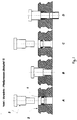
- the tubes can be shaped completely without a collar, since everyone Section with the following section.
- the blank (1) is inserted into the die (2).
- the press ram (3) in cooperation with the die (2) forms the first Blank (1) partially to a tube around (1B).
- the press ram (3) moves then back to the starting position and the next blank is in the Matrix (2) inserted (1C).
- pressing the Press ram (3) is the first pipe section with the help of the second blank fully formed and ejected (1D).
- Example 2 An alloy as produced by spray compacting in Example 1 is extruded into a round bar with an outside diameter of 74 mm. Due to the simpler geometry, a pressing speed of 1.5 m / min achieve, which means a not inconsiderable cost saving
- the rod will divided into sections of 27mm in length. These sections are then through bowl - reverse - extrusion at temperatures of 420 ° C to a bowl with an outer diameter of 74mm, an inner diameter of 67mm and molded to a height of 130mm. The thin bottom with a thickness of 4mm is then cut out when machining the pipe ends.
- An alloy as produced in Examples 1 and 2 by spray compacting has become a round rod with a Extruded 74 mm outer diameter.
- the Si primary excretions lie in a size range from 1 ⁇ m to 7 ⁇ m.
- the rod is cut into sections of one Split length of 27mm. These sections are inductive within Heated to a temperature of 560 ° C for 4 - 5 min. At this temperature is the alloy between solidus and uquidus.
- the partially fluid Bar section is mechanically stable and can still be handled.
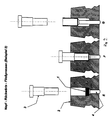
- the partially liquid rod section (1) is in one closed tool, which consists of press ram (3), die (2) and Ejector (4) is formed by cup backward extrusion.
- This will the section (1) is inserted into the tool (2E) by means of the press ram (3) formed (2F) and by the movement of the ejector (4) ejected (2G).
- the Si precipitates grow up 20 ⁇ m to 25 ⁇ m.
Landscapes
- Chemical & Material Sciences (AREA)
- Engineering & Computer Science (AREA)
- Mechanical Engineering (AREA)
- Organic Chemistry (AREA)
- Metallurgy (AREA)
- Materials Engineering (AREA)
- Chemical Kinetics & Catalysis (AREA)
- Physics & Mathematics (AREA)
- Thermal Sciences (AREA)
- Plasma & Fusion (AREA)
- Crystallography & Structural Chemistry (AREA)
- Manufacturing & Machinery (AREA)
- Powder Metallurgy (AREA)
- Extrusion Of Metal (AREA)
- Cylinder Crankcases Of Internal Combustion Engines (AREA)
- Pistons, Piston Rings, And Cylinders (AREA)
- Organic Low-Molecular-Weight Compounds And Preparation Thereof (AREA)
- Rigid Pipes And Flexible Pipes (AREA)
- Blow-Moulding Or Thermoforming Of Plastics Or The Like (AREA)
- Extrusion Moulding Of Plastics Or The Like (AREA)
- Processing And Handling Of Plastics And Other Materials For Molding In General (AREA)
Applications Claiming Priority (3)
| Application Number | Priority Date | Filing Date | Title |
|---|---|---|---|
| DE19532253A DE19532253C2 (de) | 1995-09-01 | 1995-09-01 | Verfahren zur Herstellung von dünnwandigen Rohren (II) |
| DE19532253 | 1995-09-01 | ||
| PCT/EP1996/003778 WO1997009457A1 (de) | 1995-09-01 | 1996-08-28 | Verfahren zur herstellung von dünnen rohren |
Publications (2)
| Publication Number | Publication Date |
|---|---|
| EP0848760A1 EP0848760A1 (de) | 1998-06-24 |
| EP0848760B1 true EP0848760B1 (de) | 2000-08-09 |
Family
ID=7770983
Family Applications (1)
| Application Number | Title | Priority Date | Filing Date |
|---|---|---|---|
| EP96930114A Expired - Lifetime EP0848760B1 (de) | 1995-09-01 | 1996-08-28 | Verfahren zur herstellung von laufbuchsen für verbrennungsmotoren |
Country Status (13)
| Country | Link |
|---|---|
| US (1) | US6086819A (da) |
| EP (1) | EP0848760B1 (da) |
| JP (1) | JP3582794B2 (da) |
| KR (1) | KR100269898B1 (da) |
| CN (1) | CN1066492C (da) |
| AT (1) | ATE195352T1 (da) |
| BR (1) | BR9610377A (da) |
| DE (2) | DE19532253C2 (da) |
| DK (1) | DK0848760T3 (da) |
| ES (1) | ES2151179T3 (da) |
| GR (1) | GR3034770T3 (da) |
| PT (1) | PT848760E (da) |
| WO (1) | WO1997009457A1 (da) |
Families Citing this family (18)
| Publication number | Priority date | Publication date | Assignee | Title |
|---|---|---|---|---|
| DE19532252C2 (de) * | 1995-09-01 | 1999-12-02 | Erbsloeh Ag | Verfahren zur Herstellung von Laufbuchsen |
| DE10104638A1 (de) * | 2001-02-02 | 2002-08-22 | Thyssen Krupp Automotive Ag | Verfahren zur Herstellung von Bauteilen für Flugtriebwerke und stationäre Gasturbinen |
| DE10239522B4 (de) * | 2002-08-23 | 2016-02-11 | Leica Geosystems Ag | Halteeinrichtung für ein optisches Element |
| DE102007003135B3 (de) * | 2007-01-16 | 2008-03-06 | Peak Werkstoff Gmbh | Verfahren zur Herstellung eines Zylinderkurbelgehäuses mit mehreren Zylinderlaufbuchsen sowie kurze Zylinderlaufbuchse mit daran festgelegtem Materialstreifen |
| DE102012207294A1 (de) * | 2012-05-02 | 2013-11-07 | Peak-Werkstoff Gmbh | Verfahren zur Herstellung eines Leichtmetallteils; Leichtmetallteil und Verbrennungsmotor mit Zylinderlaufbuchse aus Leichtmetallteil |
| DE102012208860A1 (de) * | 2012-05-25 | 2013-11-28 | Peak-Werkstoff Gmbh | Verfahren zur Herstellung von Kolbenringen |
| CN104988365B (zh) * | 2015-06-08 | 2017-05-03 | 哈尔滨工业大学 | 过共晶Al‑Si合金汽车用发动机缸套制备方法 |
| CN105177327A (zh) * | 2015-09-11 | 2015-12-23 | 广西南南铝加工有限公司 | 5xxx系高镁铝合金o态板材的制备方法 |
| KR20180085563A (ko) | 2017-01-19 | 2018-07-27 | 주식회사 도남알루메탈 | 튜브 압출 성형방법 |
| CN107058739B (zh) * | 2017-01-22 | 2018-08-07 | 哈尔滨理工大学 | 一种过共晶铝硅复合材料及其制造方法、应用 |
| CN107891127A (zh) * | 2017-10-31 | 2018-04-10 | 宁波百瑞天然气高压压缩机有限公司 | 一种活塞环翻砂模具 |
| CN110735025B (zh) * | 2018-02-01 | 2021-01-15 | 中国兵器工业第五九研究所 | 一种高性能铝合金收口筒体的制备方法 |
| CN108754080A (zh) * | 2018-06-13 | 2018-11-06 | 中原内配集团安徽有限责任公司 | 一种基于过共晶合金的发动机缸套 |
| US20230076653A1 (en) * | 2020-02-05 | 2023-03-09 | Giuseppe Salvadori | Apparatus and process for producing blanks of rings or tubular members |
| CN111957759B (zh) * | 2020-08-11 | 2022-07-01 | 常熟市绿一电器配件制造有限公司 | 微小通道热挤压模具结构及其制备方法 |
| CN113560827B (zh) * | 2021-08-17 | 2022-09-20 | 浙江盛林汽车部件有限公司 | 一种汽车底盘用套管的拉伸成型工艺 |
| CN115945699B (zh) * | 2022-12-30 | 2025-04-18 | 鑫精合激光科技发展(北京)有限公司 | 一种零件增材制造方法及终端设备 |
| CN117600464B (zh) * | 2024-01-23 | 2024-03-22 | 烟台大学 | 一种高温合金薄壁热挤压装置及方法 |
Family Cites Families (30)
| Publication number | Priority date | Publication date | Assignee | Title |
|---|---|---|---|---|
| DE810223C (de) * | 1949-04-14 | 1951-08-06 | Deutsche Edelstahlwerke Ag | Verfahren zur Herstellung metallischer Formkoerper |
| US3325279A (en) * | 1965-12-03 | 1967-06-13 | Dow Chemical Co | Aluminum-high silicon alloys |
| FR2343895A1 (fr) * | 1976-03-10 | 1977-10-07 | Pechiney Aluminium | Procede de fabrication de corps creux en alliages d'aluminium au silicium par filage de grenailles |
| US4155756A (en) * | 1976-03-10 | 1979-05-22 | Societe De Vente De L'aluminium Pechiney | Hollow bodies produced by powder extrusion of aluminum-silicon alloys |
| US4135922A (en) * | 1976-12-17 | 1979-01-23 | Aluminum Company Of America | Metal article and powder alloy and method for producing metal article from aluminum base powder alloy containing silicon and manganese |
| JPS57198237A (en) * | 1981-05-29 | 1982-12-04 | Riken Corp | Sliding member made of aluminum alloy and its manufacture |
| CA1230761A (en) * | 1982-07-12 | 1987-12-29 | Fumio Kiyota | Heat-resistant, wear-resistant, and high-strength aluminum alloy powder and body shaped therefrom |
| JP2787466B2 (ja) * | 1988-05-12 | 1998-08-20 | 住友電気工業株式会社 | 大径の製品用アルミニウム合金の成形方法 |
| US4989556A (en) * | 1988-10-07 | 1991-02-05 | Honda Giken Kogyo Kabushiki Kaisha | Valve spring retainer for valve operating mechanism for internal combustion engine |
| EP0366134B1 (en) * | 1988-10-27 | 1994-01-19 | Toyo Aluminium Kabushiki Kaisha | Aluminum alloy useful in powder metallurgy process |
| US5022455A (en) * | 1989-07-31 | 1991-06-11 | Sumitomo Electric Industries, Ltd. | Method of producing aluminum base alloy containing silicon |
| JP2761085B2 (ja) * | 1990-07-10 | 1998-06-04 | 昭和電工株式会社 | Al−Si系合金粉末焼結部品用の原料粉末および焼結部品の製造方法 |
| DE69120299T2 (de) * | 1990-10-31 | 1997-01-23 | Sumitomo Electric Industries | Übereutektisches aluminium-silikon-pulver und dessen herstellung |
| CH683267A5 (de) * | 1991-06-10 | 1994-02-15 | Alusuisse Lonza Services Ag | Verfahren zum Aufheizen eines Werkstückes aus einer Metallegierung. |
| JP2703840B2 (ja) * | 1991-07-22 | 1998-01-26 | 東洋アルミニウム 株式会社 | 高強度の過共晶A1―Si系粉末冶金合金 |
| US5435825A (en) * | 1991-08-22 | 1995-07-25 | Toyo Aluminum Kabushiki Kaisha | Aluminum matrix composite powder |
| US5372775A (en) * | 1991-08-22 | 1994-12-13 | Sumitomo Electric Industries, Ltd. | Method of preparing particle composite alloy having an aluminum matrix |
| EP0577436B1 (en) * | 1992-07-02 | 1997-12-03 | Sumitomo Electric Industries, Limited | Nitrogen-combined aluminum sintered alloys and method of producing the same |
| DE4230228C1 (de) * | 1992-09-10 | 1994-05-11 | Honsel Werke Ag | Bauteil aus einer Leichtmetallgußlegierung |
| JPH06172893A (ja) * | 1992-09-29 | 1994-06-21 | Matsuda Micron Kk | 耐摩耗性に優れた摺接部材及びその製造方法 |
| DE69307848T2 (de) * | 1992-12-03 | 1997-08-21 | Toyo Aluminium Kk | Hoch warmfeste und verschleissfeste Aluminiumlegierung |
| JPH06211396A (ja) * | 1993-01-13 | 1994-08-02 | Toray Ind Inc | テンタのクリップチェーンモニタリング方法及び装置 |
| JPH06211395A (ja) * | 1993-01-18 | 1994-08-02 | Mitsubishi Electric Corp | 用紙自動装填装置のピンチローラ機構 |
| JP3184367B2 (ja) * | 1993-05-24 | 2001-07-09 | 住友軽金属工業株式会社 | 高靭性Al−Si系合金の製造方法 |
| GB9311618D0 (en) * | 1993-06-04 | 1993-07-21 | Brico Eng | Aluminium alloys |
| EP0635318B1 (de) * | 1993-07-22 | 1999-04-21 | Alusuisse Technology & Management AG | Strangpressverfahren |
| GB2294102B (en) * | 1993-12-04 | 1996-06-26 | Ae Goetze Automotive Limited | Fibre-reinforced metal pistons |
| US5545487A (en) * | 1994-02-12 | 1996-08-13 | Hitachi Powdered Metals Co., Ltd. | Wear-resistant sintered aluminum alloy and method for producing the same |
| GB9517045D0 (en) * | 1995-08-19 | 1995-10-25 | Gkn Sankey Ltd | Method of manufacturing a cylinder block |
| JPH09151782A (ja) * | 1995-11-29 | 1997-06-10 | Toyota Motor Corp | シリンダブロックの製造方法 |
-
1995
- 1995-09-01 DE DE19532253A patent/DE19532253C2/de not_active Expired - Lifetime
-
1996
- 1996-08-28 DE DE59605724T patent/DE59605724D1/de not_active Expired - Lifetime
- 1996-08-28 DK DK96930114T patent/DK0848760T3/da active
- 1996-08-28 EP EP96930114A patent/EP0848760B1/de not_active Expired - Lifetime
- 1996-08-28 WO PCT/EP1996/003778 patent/WO1997009457A1/de not_active Ceased
- 1996-08-28 KR KR1019980700898A patent/KR100269898B1/ko not_active Expired - Lifetime
- 1996-08-28 AT AT96930114T patent/ATE195352T1/de active
- 1996-08-28 US US09/029,679 patent/US6086819A/en not_active Expired - Lifetime
- 1996-08-28 BR BR9610377A patent/BR9610377A/pt not_active IP Right Cessation
- 1996-08-28 JP JP51082497A patent/JP3582794B2/ja not_active Expired - Fee Related
- 1996-08-28 ES ES96930114T patent/ES2151179T3/es not_active Expired - Lifetime
- 1996-08-28 CN CN96196544A patent/CN1066492C/zh not_active Expired - Fee Related
- 1996-08-28 PT PT96930114T patent/PT848760E/pt unknown
-
2000
- 2000-11-07 GR GR20000402459T patent/GR3034770T3/el unknown
Also Published As
| Publication number | Publication date |
|---|---|
| KR19990036230A (ko) | 1999-05-25 |
| JP3582794B2 (ja) | 2004-10-27 |
| DE19532253A1 (de) | 1997-03-06 |
| DE19532253C2 (de) | 1998-07-02 |
| DE59605724D1 (de) | 2000-09-14 |
| CN1194013A (zh) | 1998-09-23 |
| DK0848760T3 (da) | 2000-09-25 |
| ATE195352T1 (de) | 2000-08-15 |
| ES2151179T3 (es) | 2000-12-16 |
| GR3034770T3 (en) | 2001-02-28 |
| CN1066492C (zh) | 2001-05-30 |
| WO1997009457A1 (de) | 1997-03-13 |
| PT848760E (pt) | 2001-01-31 |
| JPH11501990A (ja) | 1999-02-16 |
| KR100269898B1 (ko) | 2000-10-16 |
| EP0848760A1 (de) | 1998-06-24 |
| BR9610377A (pt) | 1999-07-06 |
| US6086819A (en) | 2000-07-11 |
Similar Documents
| Publication | Publication Date | Title |
|---|---|---|
| EP0858517B1 (de) | Verfahren zur herstellung von dünnen rohren | |
| EP0848760B1 (de) | Verfahren zur herstellung von laufbuchsen für verbrennungsmotoren | |
| EP0871791B1 (de) | Verfahren zur Herstellung von Laufbuchsen | |
| DE69532617T2 (de) | Target für die Kathodenzerstäubung mit ultrafeinen orienterten Körnern | |
| DE68916383T2 (de) | Verfahren zur Herstellung eines plattierten Metallrohres. | |
| DE2709844C2 (de) | Verfahren zur Herstellung von Hohlkörpern aus AlSi-Legierungen durch Fließ- oder Strangpressen von Granulat und dessen Anwendung | |
| DE3817350C2 (da) | ||
| DE69327195T2 (de) | Verfahren zum Giessen von Aluminiumlegierungen und Gusstücken | |
| DE69729488T2 (de) | Stopfen und dornstange zum walzen eines nahtlosen stahlrohres und verfahren zur herstellung eines nahtlosen stahlrohres | |
| DE69221690T2 (de) | Rotor für ölpumpe aus einer aluminiumlegierung und dessen herstellungsverfahren | |
| EP1124660A1 (de) | Zylinderkurbelgehäuse, verfahren zur herstellung der zylinderlaufbuchsen dafür und verfahren zur herstellung des zylinderkurbelgehäuses mit diesen zylinderlaufbuchsen | |
| DE19820976A1 (de) | Zylinderlaufbüchse aus übereutektischen Aluminium-Silizium-Legierungen und Verfahren zur Herstellung derselben | |
| EP1815124B1 (de) | Verfahren zur herstellung eines kolbens fuer einen verbrennungsmotor | |
| DE68915453T2 (de) | Thermomechanische behandlung von schnell erstarrten al-legierungen. | |
| DE69814498T2 (de) | Kolben für eine Brennkraftmaschine und Verfahren seiner Herstellung | |
| EP1943039B1 (de) | Verfahren zur herstellung einer verschleissbeständigen aluminiumlegierung, nach dem verfahren erhaltene aluminiumlegierung und deren verwendung | |
| EP1412113B1 (de) | Sintermetallteile mit homogener verteilung nicht homogen schmelzender komponenten, sowie verfahren zu ihrer herstellung | |
| EP1965939A1 (de) | Bauteil eines stahlwerks, wie stranggussanlage oder walzwerk, verfahren zur herstellung eines solchen bauteils sowie anlage zur erzeugung oder verarbeitung von metallischen halbzeugen | |
| DE69316488T2 (de) | Verfahren zum Warmschmieden bei Ultrahoch -Temperatur | |
| DE29823988U1 (de) | Zylinderlaufbüchse aus übereutektischen Aluminium-Silizium-Legierungen | |
| EP1945393A1 (de) | Verfahren zur herstellung eines zylinderkurbelgehäusses sowie ein nach dem verfahren hergestelites zylinderkurbelgehäuse |
Legal Events
| Date | Code | Title | Description |
|---|---|---|---|
| PUAI | Public reference made under article 153(3) epc to a published international application that has entered the european phase |
Free format text: ORIGINAL CODE: 0009012 |
|
| 17P | Request for examination filed |
Effective date: 19980324 |
|
| AK | Designated contracting states |
Kind code of ref document: A1 Designated state(s): AT BE CH DE DK ES FI FR GB GR IE IT LI LU MC NL PT SE |
|
| GRAG | Despatch of communication of intention to grant |
Free format text: ORIGINAL CODE: EPIDOS AGRA |
|
| GRAG | Despatch of communication of intention to grant |
Free format text: ORIGINAL CODE: EPIDOS AGRA |
|
| GRAH | Despatch of communication of intention to grant a patent |
Free format text: ORIGINAL CODE: EPIDOS IGRA |
|
| RTI1 | Title (correction) |
Free format text: PROCESS FOR MANUFACTURING CYLINDER LINERS FOR INTERNAL COMBUSTION ENGINES |
|
| 17Q | First examination report despatched |
Effective date: 19991214 |
|
| GRAH | Despatch of communication of intention to grant a patent |
Free format text: ORIGINAL CODE: EPIDOS IGRA |
|
| GRAA | (expected) grant |
Free format text: ORIGINAL CODE: 0009210 |
|
| AK | Designated contracting states |
Kind code of ref document: B1 Designated state(s): AT BE CH DE DK ES FI FR GB GR IE IT LI LU MC NL PT SE |
|
| REF | Corresponds to: |
Ref document number: 195352 Country of ref document: AT Date of ref document: 20000815 Kind code of ref document: T |
|
| REG | Reference to a national code |
Ref country code: CH Ref legal event code: EP |
|
| ET | Fr: translation filed | ||
| PG25 | Lapsed in a contracting state [announced via postgrant information from national office to epo] |
Ref country code: LU Free format text: LAPSE BECAUSE OF NON-PAYMENT OF DUE FEES Effective date: 20000828 |
|
| GBT | Gb: translation of ep patent filed (gb section 77(6)(a)/1977) |
Effective date: 20000809 |
|
| REG | Reference to a national code |
Ref country code: IE Ref legal event code: FG4D Free format text: GERMAN |
|
| REF | Corresponds to: |
Ref document number: 59605724 Country of ref document: DE Date of ref document: 20000914 |
|
| REG | Reference to a national code |
Ref country code: CH Ref legal event code: NV Representative=s name: E. BLUM & CO. PATENTANWAELTE |
|
| REG | Reference to a national code |
Ref country code: DK Ref legal event code: T3 |
|
| PG25 | Lapsed in a contracting state [announced via postgrant information from national office to epo] |
Ref country code: MC Free format text: THE PATENT HAS BEEN ANNULLED BY A DECISION OF A NATIONAL AUTHORITY Effective date: 20001009 |
|
| ITF | It: translation for a ep patent filed | ||
| REG | Reference to a national code |
Ref country code: ES Ref legal event code: FG2A Ref document number: 2151179 Country of ref document: ES Kind code of ref document: T3 |
|
| REG | Reference to a national code |
Ref country code: PT Ref legal event code: SC4A Free format text: AVAILABILITY OF NATIONAL TRANSLATION Effective date: 20001026 |
|
| PLBE | No opposition filed within time limit |
Free format text: ORIGINAL CODE: 0009261 |
|
| STAA | Information on the status of an ep patent application or granted ep patent |
Free format text: STATUS: NO OPPOSITION FILED WITHIN TIME LIMIT |
|
| 26N | No opposition filed | ||
| REG | Reference to a national code |
Ref country code: GB Ref legal event code: IF02 |
|
| REG | Reference to a national code |
Ref country code: CH Ref legal event code: PFA Owner name: ERBSLOEH AKTIENGESELLSCHAFT Free format text: ERBSLOEH AKTIENGESELLSCHAFT#SIEBENEICKER STRASSE 235#42553 VELBERT (DE) -TRANSFER TO- ERBSLOEH AKTIENGESELLSCHAFT#SIEBENEICKER STRASSE 235#42553 VELBERT (DE) |
|
| PGFP | Annual fee paid to national office [announced via postgrant information from national office to epo] |
Ref country code: DK Payment date: 20110822 Year of fee payment: 16 Ref country code: CH Payment date: 20110824 Year of fee payment: 16 |
|
| PGFP | Annual fee paid to national office [announced via postgrant information from national office to epo] |
Ref country code: SE Payment date: 20120821 Year of fee payment: 17 Ref country code: GB Payment date: 20120821 Year of fee payment: 17 Ref country code: IE Payment date: 20120821 Year of fee payment: 17 Ref country code: FI Payment date: 20120813 Year of fee payment: 17 |
|
| PGFP | Annual fee paid to national office [announced via postgrant information from national office to epo] |
Ref country code: GR Payment date: 20120821 Year of fee payment: 17 |
|
| PGFP | Annual fee paid to national office [announced via postgrant information from national office to epo] |
Ref country code: IT Payment date: 20120823 Year of fee payment: 17 Ref country code: ES Payment date: 20120828 Year of fee payment: 17 Ref country code: BE Payment date: 20120824 Year of fee payment: 17 Ref country code: FR Payment date: 20120906 Year of fee payment: 17 |
|
| PGFP | Annual fee paid to national office [announced via postgrant information from national office to epo] |
Ref country code: PT Payment date: 20120228 Year of fee payment: 17 Ref country code: NL Payment date: 20120821 Year of fee payment: 17 |
|
| PGFP | Annual fee paid to national office [announced via postgrant information from national office to epo] |
Ref country code: AT Payment date: 20120813 Year of fee payment: 17 |
|
| BERE | Be: lapsed |
Owner name: *ERBSLOH A.G. Effective date: 20130831 |
|
| REG | Reference to a national code |
Ref country code: PT Ref legal event code: MM4A Free format text: LAPSE DUE TO NON-PAYMENT OF FEES Effective date: 20140228 |
|
| REG | Reference to a national code |
Ref country code: NL Ref legal event code: V1 Effective date: 20140301 |
|
| REG | Reference to a national code |
Ref country code: CH Ref legal event code: PL Ref country code: DK Ref legal event code: EBP Effective date: 20130831 |
|
| REG | Reference to a national code |
Ref country code: SE Ref legal event code: EUG |
|
| REG | Reference to a national code |
Ref country code: AT Ref legal event code: MM01 Ref document number: 195352 Country of ref document: AT Kind code of ref document: T Effective date: 20130828 |
|
| GBPC | Gb: european patent ceased through non-payment of renewal fee |
Effective date: 20130828 |
|
| REG | Reference to a national code |
Ref country code: GR Ref legal event code: ML Ref document number: 20000402459 Country of ref document: GR Effective date: 20140305 |
|
| PG25 | Lapsed in a contracting state [announced via postgrant information from national office to epo] |
Ref country code: SE Free format text: LAPSE BECAUSE OF NON-PAYMENT OF DUE FEES Effective date: 20130829 Ref country code: NL Free format text: LAPSE BECAUSE OF NON-PAYMENT OF DUE FEES Effective date: 20140301 Ref country code: LI Free format text: LAPSE BECAUSE OF NON-PAYMENT OF DUE FEES Effective date: 20130831 Ref country code: FI Free format text: LAPSE BECAUSE OF NON-PAYMENT OF DUE FEES Effective date: 20130828 Ref country code: CH Free format text: LAPSE BECAUSE OF NON-PAYMENT OF DUE FEES Effective date: 20130831 |
|
| REG | Reference to a national code |
Ref country code: IE Ref legal event code: MM4A |
|
| REG | Reference to a national code |
Ref country code: FR Ref legal event code: ST Effective date: 20140430 |
|
| PG25 | Lapsed in a contracting state [announced via postgrant information from national office to epo] |
Ref country code: BE Free format text: LAPSE BECAUSE OF NON-PAYMENT OF DUE FEES Effective date: 20130831 Ref country code: AT Free format text: LAPSE BECAUSE OF NON-PAYMENT OF DUE FEES Effective date: 20130828 Ref country code: IT Free format text: LAPSE BECAUSE OF NON-PAYMENT OF DUE FEES Effective date: 20130828 Ref country code: GR Free format text: LAPSE BECAUSE OF NON-PAYMENT OF DUE FEES Effective date: 20140305 |
|
| PG25 | Lapsed in a contracting state [announced via postgrant information from national office to epo] |
Ref country code: PT Free format text: LAPSE BECAUSE OF NON-PAYMENT OF DUE FEES Effective date: 20140228 |
|
| PG25 | Lapsed in a contracting state [announced via postgrant information from national office to epo] |
Ref country code: IE Free format text: LAPSE BECAUSE OF NON-PAYMENT OF DUE FEES Effective date: 20130828 Ref country code: GB Free format text: LAPSE BECAUSE OF NON-PAYMENT OF DUE FEES Effective date: 20130828 |
|
| PG25 | Lapsed in a contracting state [announced via postgrant information from national office to epo] |
Ref country code: FR Free format text: LAPSE BECAUSE OF NON-PAYMENT OF DUE FEES Effective date: 20130902 |
|
| REG | Reference to a national code |
Ref country code: ES Ref legal event code: FD2A Effective date: 20140905 |
|
| PG25 | Lapsed in a contracting state [announced via postgrant information from national office to epo] |
Ref country code: DK Free format text: LAPSE BECAUSE OF NON-PAYMENT OF DUE FEES Effective date: 20130831 |
|
| PGFP | Annual fee paid to national office [announced via postgrant information from national office to epo] |
Ref country code: DE Payment date: 20140821 Year of fee payment: 19 |
|
| PG25 | Lapsed in a contracting state [announced via postgrant information from national office to epo] |
Ref country code: ES Free format text: LAPSE BECAUSE OF NON-PAYMENT OF DUE FEES Effective date: 20130829 |
|
| REG | Reference to a national code |
Ref country code: DE Ref legal event code: R119 Ref document number: 59605724 Country of ref document: DE |
|
| PG25 | Lapsed in a contracting state [announced via postgrant information from national office to epo] |
Ref country code: DE Free format text: LAPSE BECAUSE OF NON-PAYMENT OF DUE FEES Effective date: 20160301 |