EP0848413B1 - Compact apparatus and method for storing and loading semiconductor wafer carriers - Google Patents
Compact apparatus and method for storing and loading semiconductor wafer carriers Download PDFInfo
- Publication number
- EP0848413B1 EP0848413B1 EP97309950A EP97309950A EP0848413B1 EP 0848413 B1 EP0848413 B1 EP 0848413B1 EP 97309950 A EP97309950 A EP 97309950A EP 97309950 A EP97309950 A EP 97309950A EP 0848413 B1 EP0848413 B1 EP 0848413B1
- Authority
- EP
- European Patent Office
- Prior art keywords
- wafer
- fabrication tool
- wafer carrier
- load
- vertical transfer
- Prior art date
- Legal status (The legal status is an assumption and is not a legal conclusion. Google has not performed a legal analysis and makes no representation as to the accuracy of the status listed.)
- Expired - Lifetime
Links
Images


Classifications
-
- H—ELECTRICITY
- H01—ELECTRIC ELEMENTS
- H01L—SEMICONDUCTOR DEVICES NOT COVERED BY CLASS H10
- H01L21/00—Processes or apparatus adapted for the manufacture or treatment of semiconductor or solid state devices or of parts thereof
- H01L21/67—Apparatus specially adapted for handling semiconductor or electric solid state devices during manufacture or treatment thereof; Apparatus specially adapted for handling wafers during manufacture or treatment of semiconductor or electric solid state devices or components ; Apparatus not specifically provided for elsewhere
- H01L21/68—Apparatus specially adapted for handling semiconductor or electric solid state devices during manufacture or treatment thereof; Apparatus specially adapted for handling wafers during manufacture or treatment of semiconductor or electric solid state devices or components ; Apparatus not specifically provided for elsewhere for positioning, orientation or alignment
-
- H—ELECTRICITY
- H01—ELECTRIC ELEMENTS
- H01L—SEMICONDUCTOR DEVICES NOT COVERED BY CLASS H10
- H01L21/00—Processes or apparatus adapted for the manufacture or treatment of semiconductor or solid state devices or of parts thereof
- H01L21/67—Apparatus specially adapted for handling semiconductor or electric solid state devices during manufacture or treatment thereof; Apparatus specially adapted for handling wafers during manufacture or treatment of semiconductor or electric solid state devices or components ; Apparatus not specifically provided for elsewhere
- H01L21/677—Apparatus specially adapted for handling semiconductor or electric solid state devices during manufacture or treatment thereof; Apparatus specially adapted for handling wafers during manufacture or treatment of semiconductor or electric solid state devices or components ; Apparatus not specifically provided for elsewhere for conveying, e.g. between different workstations
- H01L21/67763—Apparatus specially adapted for handling semiconductor or electric solid state devices during manufacture or treatment thereof; Apparatus specially adapted for handling wafers during manufacture or treatment of semiconductor or electric solid state devices or components ; Apparatus not specifically provided for elsewhere for conveying, e.g. between different workstations the wafers being stored in a carrier, involving loading and unloading
- H01L21/67769—Storage means
-
- Y—GENERAL TAGGING OF NEW TECHNOLOGICAL DEVELOPMENTS; GENERAL TAGGING OF CROSS-SECTIONAL TECHNOLOGIES SPANNING OVER SEVERAL SECTIONS OF THE IPC; TECHNICAL SUBJECTS COVERED BY FORMER USPC CROSS-REFERENCE ART COLLECTIONS [XRACs] AND DIGESTS
- Y10—TECHNICAL SUBJECTS COVERED BY FORMER USPC
- Y10S—TECHNICAL SUBJECTS COVERED BY FORMER USPC CROSS-REFERENCE ART COLLECTIONS [XRACs] AND DIGESTS
- Y10S414/00—Material or article handling
- Y10S414/135—Associated with semiconductor wafer handling
- Y10S414/139—Associated with semiconductor wafer handling including wafer charging or discharging means for vacuum chamber
-
- Y—GENERAL TAGGING OF NEW TECHNOLOGICAL DEVELOPMENTS; GENERAL TAGGING OF CROSS-SECTIONAL TECHNOLOGIES SPANNING OVER SEVERAL SECTIONS OF THE IPC; TECHNICAL SUBJECTS COVERED BY FORMER USPC CROSS-REFERENCE ART COLLECTIONS [XRACs] AND DIGESTS
- Y10—TECHNICAL SUBJECTS COVERED BY FORMER USPC
- Y10S—TECHNICAL SUBJECTS COVERED BY FORMER USPC CROSS-REFERENCE ART COLLECTIONS [XRACs] AND DIGESTS
- Y10S414/00—Material or article handling
- Y10S414/135—Associated with semiconductor wafer handling
- Y10S414/14—Wafer cassette transporting
Definitions
- the present invention relates generally to semiconductor wafer fabrication systems, and to an improved method and apparatus for storing and loading semiconductor wafer carriers at a given semiconductor wafer fabrication tool.
- the present application is related to US-A-5,957,648.
- the MINI BUFFER comprises a series of vertically arranged shelves and one or more load ports for access by the tool's loader robot, and/or for access by factory transport agents (i.e., the mechanism that transfers wafer carriers from the factory to the buffer apparatus' factory load port).
- factory transport agents i.e., the mechanism that transfers wafer carriers from the factory to the buffer apparatus' factory load port.
- one MINI BUFFER is positioned near each load lock, a distance from the load lock sufficient to accommodate the axis of rotation of a front loader robot.
- the loader robot may then access either MINI BUFFER to obtain a wafer carrier for loading to either load lock.
- US-A-5,957,648 discloses a Factory Automation Apparatus and Method for Handling, Moving and Storing Semiconductor Wafer Carriers, which provides an apparatus which advantageously allows for independent operation of the factory transport agent and the fabrication tool's loader mechanism, and provides for local interconnection of fabrication tools in a reduced footprint configuration.
- EP-A-0675523 discloses a method of providing local area buffer of wafers for loading to a fabrication tool comprising receiving a wafer at the fabrication tool, elevating a wafer carrier to a height greater than the height of the fabrication tool, placing the wafer above the fabrication tool, and lowering the wafer carrier to the tool load port of the fabrication tool.
- This invention provides an apparatus for buffering water carriers to be loaded to a fabrication tool comprising a first load port for receiving wafer carriers; a first vertical transfer mechanism for wafer carriers, operatively coupling said first load port; at least one storage location for wafer carriers operatively coupling said first vertical transfer mechanism; and a first wafer exchange port for transferring a plurality of wafers from wafer carriers to the fabrication tool; wherein the first vertical transfer mechanism is for lifting wafer carriers to a height greater than that of the fabrication tool; the at least one storage location is located above the fabrication tool; in that the apparatus further comprises a second vertical transfer mechanism for wafer carriers operatively coupling said at least one storage location for lowering the wafer carrier for loading into the fabrication tool;; and in that the first wafer exchange port operatively couples the second vertical transfer mechanism.
- the present invention provides a compact method and apparatus for buffering wafer carriers to be loaded to a fabrication tool (i.e. a load buffer) which eliminates the need for the front loader robot required of prior art systems and provides overhead storage locations, therefore greatly reducing footprint as compared to prior art systems.
- the load buffer features 1) two physically separate load ports; a load port for transferring wafer carriers between the factory and the load buffer apparatus, and a wafer exchange port for transferring either the entire wafer carrier, or one or more wafers at a time between the load buffer apparatus and the fabrication tool and 2) overhead storage locations.
- the load buffer will have two pairs of physically separated load ports comprising a first load port and a first wafer exchange port, and a second load port and a second wafer exchange port respectively.
- the load buffer includes top opening load locks to receive wafers for loading into the fabrication tool.
- Each load lock includes a loader mechanisms for transferring wafers or cassettes of wafers between the wafer exchange port and the load lock chamber.
- the physical separation of the load port and the wafer exchange port allows for independent loading of both the load buffer apparatus and the fabrication tool.
- the independent loading of the load buffer apparatus and the fabrication tool allows a factory transport agent to operate independent of the operation of the fabrication tool's loader mechanism, making factory-wide automation more flexible and efficient.
- the overhead storage locations are above the fabrication tool (as used herein a first feature described as "above” a second feature shall mean the first and second feature have at least partially overlapping footprints).
- the overhead storage locations are substantially above the fabrication tool (i.e., the footprint of the overhead storage locations substantially overlap the footprint of the fabrication tool), and most preferably the overhead storage locations are completely above the fabrication tool (i.e., the footprint of the overhead storage locations completely overlap the footprint of the fabrication tool).
- the combination of overhead storage and top opening load locks allows for significant reduction in the footprint of the automated local area semiconductor wafer fabrication system (i.e., the combined fabrication tool and load buffer).
- the overhead storage and top opening load locks provide the fabrication tool with a constant buffer supply of wafer carriers in a significantly reduced footprint configuration.
- the inventive load buffer apparatus comprises: a first load port, a first vertical transfer mechanism for elevating wafer carriers to a height greater than that of the fabrication tool; at least one storage location located above the fabrication tool operatively coupling the first vertical transfer mechanism; a second vertical transfer mechanism, operatively coupling the at least one storage location, for lowering the wafer carrier; and a first wafer exchange port, operatively coupling the second vertical transfer mechanism.
- operatively coupling means configured such that a wafer carrier can be transferred between the identified components.
- the at least one storage location comprises one or more shelves which are operatively coupled to both the first and second vertical transfer mechanisms, i.e., the shelves are located such that wafer carriers can be passed from the first vertical transfer mechanism to the second vertical transfer mechanism via the series of shelves.
- the first and second vertical transfer mechanisms comprise a first and second robot each having both a y-axis component and an x-axis component; the x-axis component being movably coupled to the y-axis component such that the x-axis component can travel along the length of the y-axis component.
- the first robot is configured so as to access the first load port and the second load port from a first and second position above the first and second load port respectively; and the second robot is configured so as to access the first wafer exchange port and the second wafer exchange port from a third and fourth position above the first and second wafer exchange port respectively.
- the first, second, third and fourth positions are substantially above, and most preferably completely above the respective port.
- the inventive load buffer further comprises a top opening load lock such as that disclosed in US-A-539105 entitled “Micro-Environmental Load Lock” the entirety of which is hereby incorporated by reference.
- the top opening load lock has a first lid comprising a wafer carrier engaging mechanism which engages a second lid (the lid of a pod type wafer carrier positioned on the first wafer exchange port) such that elevation of the first lid causes the second lid to elevate, opening the wafer carrier positioned on the first wafer exchange port.
- the wafer exchange port is positioned above the fabrication tool's transfer chamber and wafers are extracted therefrom and transferred to a position within the open first load lock by a loader first loader mechanism such as the wafer extraction platform disclosed in EP-A-0848412.
- FIG. 1 is a side view of an inventive load buffer 11.
- the load buffer 1I comprises a first and second vertical transfer mechanism comprised of a first robot 13 and a second robot 15, respectively.
- the first robot 13 comprises a first y-axis component 17 and a first x-axis component 19 movably coupled to the first y-axis component 17 such that the first x-axis component 19 may travel along the length of the first y-axis component 17.
- the second robot 15 comprises a second y-axis component 21 and a second x-axis component 23 movably coupled to the second y-axis component 21 such that the second x-axis component 23 may travel along the length of the second y-axis component 21.
- the first robot 13 is configured such that when the first x-axis component 19 is at the lower portion of the first y-axis component 17 it may access a first load port 27 (preferably a SEMI E 15 type load port) and such that when the first x-axis component 19 is at the upper portion of the first y-axis component 17 it may access a first overhead load port (not shown) which provides access to a first overhead wafer carrier transport system such as a monorail, referenced generally by the numeral 29a of FIG. 1.
- a first load port 27 preferably a SEMI E 15 type load port
- the second robot 15 is configured such that when the second x-axis component 23 is at the lower portion of the second y-axis component 21 it may access a first wafer exchange port 31 and, optionally, such that when the second x-axis component 23 is at the upper portion of the second y-axis component 23 it may access an optional second overhead load port which provides access to a second overhead wafer carrier transport system such as a monorail, referenced generally by the numeral 29b in FIG. 1.
- Both the first x-axis component 19 and the second x-axis component 23 are configured so as to reach any of the storage locations 25a, 25b.
- each load port, each overhead load port and each wafer exchange port may simply comprise a predetermined location.
- the first wafer exchange port 31 is preferably located substantially or completely above a fabrication tool 33 having at least a transfer chamber 32, a process chamber 34 and a first load lock 35. Most preferably the first wafer exchange port 31 is located above the transfer chamber 32 of the fabrication tool 33.
- the first wafer exchange port 31 is operatively coupled to the first load lock 35 via a first loader mechanism referenced generally by the numeral 37 of FIG. 1.
- the first loader mechanism 37 comprises a wafer cassette platform such as that described in EP-A-0848412 that extends outside the open load lock 35 to extract wafers from a cassette located on the first wafer exchange port 31.
- the first load lock 35 has a first lid 39 and a lift-lower mechanism 41.
- the first loader mechanism 37 is positioned on lift-lower mechanism 41.
- the first loader mechanism 37 extends horizontally, extracts one or more wafers from a first wafer carrier 43 (or, alternatively, can transfer the entire wafer carrier) located on the first wafer exchange port 31 and retracts carrying the extracted wafers (or the entire cassette) into position on the lift-lower mechanism 41.
- the lift-lower mechanism 41 then lowers the wafers (or the cassette) as the first lid 39 lowers.
- the first lid 39 has a wafer carrier-engaging mechanism referenced generally by the numeral 45 of FIG. 1 which will engage a second lid 47 of a first wafer carrier 43 located on the first wafer exchange port 31 causing the second lid 47 to elevate as the first lid 39 elevates.
- the first wafer carrier 43 is open and ready for the first loader mechanism 37 to extract wafers for loading to the first load lock 35.
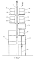
- FIG. 2 is a front elevational view of the load buffer 11 of FIG. 1 which shows a preferred arrangement of four storage locations 25a, 25b, 25c, and 25d, above the first load lock 35 and a second load lock 49.
- the first load lock 35 is open with the first lid 39 elevated and the first wafer carrier 43 loaded on the lift-lower mechanism 41 for subsequent lowering into the first load lock 35.
- a second wafer carrier 51, a third wafer carrier 53, a fourth wafer carrier 55 and a fifth wafer carrier 57 are in storage on the storage locations 25a, 25b, 25c and 25d, respectively.
- FIG. 3 is a top plan view of the load buffer 11 of FIGs. 1 and 2 which shows a preferred footprint of the load buffer 11, and which shows in pertinent part, a preferred footprint of the local area semiconductor wafer fabrication system.
- the four primary horizontal positions of the first x-axis component 19 and of the second x-axis component 23 are represented as 19a, 19b, 19c, and 19d, and 23a, 23b, 23c, and 23d respectively. However, it is understood that the first x-axis component 19 and the second x-axis component 23 each occupy only one of these positions at a given time.
- the primary vertical positions of the first x-axis component 19 and of the second x-axis component 23 are shown sequentially in FIGs. 4A-4F and FIGs.
- the first load port 27 and a second load port 59 are advantageously positioned directly adjacent the first load lock 35 and the second load lock 49 of the fabrication tool 33, resulting in the overall footprint of the local area semiconductor wafer fabrication system being considerably smaller than that of prior art systems which require sufficient space for a front loader robot.
- Such advantageous positioning of the first load port 27 and the second load port 59 is possible because wafer carriers entering the load buffer 11 via the first load port 27 or the second load port 59 are extracted from the top of the first load port 27 and the second load port 59, respectively, rather than from the sides thereof.
- first load port 27 and the second load port 59 are loaded and unloaded from above, they may be positioned in close proximity to each other, unlike side loaded prior art systems whose load ports must be positioned a sufficient distance from each other to accommodate the loader robot's axis of rotation.
- storage locations 25a and 25c are positioned above the first load lock 35 and the second load lock 49, respectively, and the first wafer exchange port 31 and a second wafer exchange port 61 are positioned above the transfer chamber 32 of the fabrication tool 33.
- the location of the plurality of storage locations 25a-25d, the first wafer exchange port 31 and the second wafer exchange port 61 above the fabrication tool allows the footprint of the inventive local area semiconductor wafer fabrication system to be significantly smaller than that of prior art systems.
- the smaller footprint provided by the present invention reduces the systems cost of ownership which in turn reduces the cost of each unit produced.
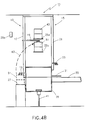
- FIGs. 4A-4F are side elevational views of the load buffer 11, which are useful in explaining a first aspect of wafer carrier transport through the load buffer 11.
- the components of the load buffer 11 are described above with reference to FIG. 1 and are therefore not repeated here.
- the entire load buffer apparatus 11 is maintained under a vacuum hood. However, it is understood that if the load buffer 11 were not under vacuum, the steps of opening a pod type wafer carrier and loading the wafers to the load lock would be performed within an enclosed vacuum chamber that would surround each wafer exchange port and the open load lock associated therewith.
- the first wafer carrier 43 is in storage at the storage location 25a.
- a second wafer carrier 51 is placed on the first load port 27 by, for example, an operator, automatic guided vehicle (AGV) or rail-guided vehicle (RGV), and the first x-axis component 19 of the first robot 13 lowers to pick up the second wafer carrier 51, as shown in FIG. 4A.
- the second robot 15 operates independently of the first robot 13, and may therefore be in any required position at a given time.
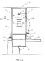
- the first x-axis component 19 lifts the second wafer carrier 51 and pivots to deposit the second wafer carrier 51 on the storage location 25b, as represented by arrow 63.
- the first x-axis component 19 may pivot and lower to pick up the third wafer carrier 53 from the first load port 27, as the second x-axis component 23 of the second robot 15 picks up the first wafer carrier 43 from the storage location 25a, pivots, lowers and deposits the first wafer carrier 43 at the first wafer exchange port 31, as represented by the arrow 65.
- the first lid 39 of the first load lock 35 elevates, and the wafer carrier-engaging mechanism 45, which engages the second lid 47, of the first wafer carrier 43, causes the second lid 47 to elevate.
- the first wafer carrier 43 is open and any number of wafers or the entire cassette 43a (i.e., the contents of the open pod type first wafer carrier 43) may be transferred from the first wafer exchange port 31 to the open first load lock 35.
- the first loader mechanism 37 may be a conventional apparatus, or, preferably, is as described in EP-A-0 848 412.
- the apparatus described in this application comprises a slotted assembly which extends to position the slots beneath the wafers to be extracted.
- the assembly then elevates, lifting the wafers, and retracts.
- the assembly can be modified such that the number of slots correspond to the number of wafers to be extracted, or can be modified to extend to a position beneath the entire cassette, thus transporting the entire cassette when the assembly retracts.
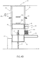
- FIG. 4E shows the wafer cassette 43a (extracted from the open first wafer carrier 43) positioned on the lift-lower mechanism 41 for subsequent lowering into the first load lock 35.
- FIG. 4F shows the wafer cassette 43a positioned within the first load lock 35, and the first lid 39 of the first load lock 35 in the closed position. Thereafter wafers may be extracted from the first load lock 35 and processed within the fabrication tool 33.
- the empty first wafer carrier 43 can be closed and moved to one of the storage locations 25a-25d or can remain positioned on first wafer exchange port 31 until wafers have been processed and returned to the first wafer carrier 43.
- the first robot 13 and the second robot 15 may continue to operate independent of the loading of the first wafer carrier 43 from the first wafer exchange port 31 to the first load lock 35.
- the first robot 13 may continue transferring wafer carriers between the first load port 27 and/or the overhead load port (e.g., a predetermined location along the monorail 29) and the plurality of storage locations 25a-25d; and the second robot 15 is able to pick up wafer carriers as required from the plurality of storage locations 25a-25d, and deposit them at either the first wafer exchange port 31 or the second wafer exchange port 61, provided the particular wafer exchange port is vacant.
- the configuration of the load buffer 11 advantageously enables independent operation of the first robot 13 and the second robot 15, and enables independent loading and unloading of each pair of load ports (e.g., the first load port and the first wafer exchange port) and the overhead load ports.
- load ports e.g., the first load port and the first wafer exchange port
- the specific operation of the load buffer 11 described with reference to FIGs. 4A- 4F is merely exemplary.
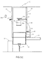
- FIGs. 5A-5C are side elevational views of the load buffer of FIG. 2, which are useful in explaining a second aspect of wafer carrier transport therethrough.
- the first x-axis component 19 of the first robot 13 pivots to pickup the first wafer carrier 43 from the monorail 29.
- the first x-axis component 19 lowers and pivots about the first y-axis component 17 to deposit the first wafer carrier 43 on the storage location 25b, as represented by the arrow 67.
- FIG. 5A-5C are side elevational views of the load buffer of FIG. 2, which are useful in explaining a second aspect of wafer carrier transport therethrough.
- the first x-axis component 19 of the first robot 13 pivots to pickup the first wafer carrier 43 from the monorail 29.
- the first x-axis component 19 lowers and pivots about the first y-axis component 17 to deposit the first wafer carrier 43 on the storage location 25b, as represented by the arrow 67.
- FIG. 5A-5C are side elevational views of the
- the second x-axis component 23 of the second robot 15 picks up the first wafer carrier 43 from the storage location 25b and pivots about the second y-axis component 21 and lowers to deposit the first wafer carrier 43 on the first wafer exchange port 31, as represented by arrow 69. Thereafter the first wafer carrier 43 is opened and lowered into the first load lock 35 as previously described with reference to FIGs. 4D-4F. While only the first wafer carrier 43 is shown traveling through the load buffer 11, it is understood that when the first x-axis component 19 and the second x-axis component 23 are not transporting the first wafer carrier 43, they may be picking up, transporting, or depositing other wafer carriers at any location within load buffer 11, as previously described.
- the operation of the first robot 13 and the second robot 15 may be synchronous at certain times, and also may operate asynchronously at other times. Therefore it is understood that the specific operation of the load buffer 11 described with reference to FIGs. 5A-5C is merely exemplary.
- the lid of load lock 35 elevates, the lift lower mechanism 41 lifts the wafers to the elevation of the first wafer exchange port 31, and the first loader mechanism 37 returns the wafers to the cassette 43 positioned on the wafer exchange port 31.
- the first lid 39 of load lock 35 lowers, lift/lower mechanism 41 lowers, and the second lid 47 of the wafer carrier 43 lowers, sealing around the cassette 43a.
- the second robot 15 transfers the wafer carrier 43 either to a storage shelf 25 or to the second overhead load port. If the second robot 15 places the wafer carrier 43 on one of the storage shelves 25, the first robot 13 may then transfer the wafer carrier 43 either to the first load port 27 or to the first overhead load port.
- a wafer carrier full of processed wafers travels backward through the load buffer 11 in the same manner as a wafer carrier of unprocessed wafers travels forward through the load buffer 11, only the direction of travel changes.
- Each robot elevates a wafer carrier between the respective load port or wafer exchange port and the overhead load ports or storage shelves.
- the term "elevate” refers to any y-axis movement and therefore includes both lifting and lowering.
- wafer carriers may be traveling both forward and backward through the load buffer 11.
- a robot may transfer a first wafer carrier to the storage shelves or to the overhead load ports, and then immediately pick up a second wafer carrier for transfer to one of the load ports or to the wafer exchange ports.
- FIGs. 1, 4A-F and 5A-C only the first side of the load buffer 11 is shown and described (i.e., the first load port through the first wafer exchange port) it is understood that the configuration and operation of the second side of the load buffer 11 (i.e., the second load port through the second wafer exchange port) is identical to that disclosed.
Landscapes
- Engineering & Computer Science (AREA)
- Physics & Mathematics (AREA)
- Condensed Matter Physics & Semiconductors (AREA)
- General Physics & Mathematics (AREA)
- Manufacturing & Machinery (AREA)
- Computer Hardware Design (AREA)
- Microelectronics & Electronic Packaging (AREA)
- Power Engineering (AREA)
- Container, Conveyance, Adherence, Positioning, Of Wafer (AREA)
- Warehouses Or Storage Devices (AREA)
Priority Applications (1)
| Application Number | Priority Date | Filing Date | Title |
|---|---|---|---|
| EP03006108A EP1335413A1 (en) | 1996-12-11 | 1997-12-10 | Compact apparatus and method for storing and loading semiconductor wafer carriers |
Applications Claiming Priority (2)
| Application Number | Priority Date | Filing Date | Title |
|---|---|---|---|
| US763596 | 1996-12-11 | ||
| US08/763,596 US5964561A (en) | 1996-12-11 | 1996-12-11 | Compact apparatus and method for storing and loading semiconductor wafer carriers |
Related Child Applications (1)
| Application Number | Title | Priority Date | Filing Date |
|---|---|---|---|
| EP03006108A Division EP1335413A1 (en) | 1996-12-11 | 1997-12-10 | Compact apparatus and method for storing and loading semiconductor wafer carriers |
Publications (3)
| Publication Number | Publication Date |
|---|---|
| EP0848413A2 EP0848413A2 (en) | 1998-06-17 |
| EP0848413A3 EP0848413A3 (en) | 2000-09-20 |
| EP0848413B1 true EP0848413B1 (en) | 2004-03-17 |
Family
ID=25068283
Family Applications (2)
| Application Number | Title | Priority Date | Filing Date |
|---|---|---|---|
| EP97309950A Expired - Lifetime EP0848413B1 (en) | 1996-12-11 | 1997-12-10 | Compact apparatus and method for storing and loading semiconductor wafer carriers |
| EP03006108A Withdrawn EP1335413A1 (en) | 1996-12-11 | 1997-12-10 | Compact apparatus and method for storing and loading semiconductor wafer carriers |
Family Applications After (1)
| Application Number | Title | Priority Date | Filing Date |
|---|---|---|---|
| EP03006108A Withdrawn EP1335413A1 (en) | 1996-12-11 | 1997-12-10 | Compact apparatus and method for storing and loading semiconductor wafer carriers |
Country Status (7)
| Country | Link |
|---|---|
| US (1) | US5964561A (ja) |
| EP (2) | EP0848413B1 (ja) |
| JP (1) | JPH10223728A (ja) |
| KR (1) | KR19980064020A (ja) |
| DE (1) | DE69728120T2 (ja) |
| SG (1) | SG71070A1 (ja) |
| TW (1) | TW362255B (ja) |
Families Citing this family (25)
| Publication number | Priority date | Publication date | Assignee | Title |
|---|---|---|---|---|
| US6447232B1 (en) * | 1994-04-28 | 2002-09-10 | Semitool, Inc. | Semiconductor wafer processing apparatus having improved wafer input/output handling system |
| US6540466B2 (en) * | 1996-12-11 | 2003-04-01 | Applied Materials, Inc. | Compact apparatus and method for storing and loading semiconductor wafer carriers |
| US6579052B1 (en) * | 1997-07-11 | 2003-06-17 | Asyst Technologies, Inc. | SMIF pod storage, delivery and retrieval system |
| US6161054A (en) * | 1997-09-22 | 2000-12-12 | On-Line Technologies, Inc. | Cell control method and apparatus |
| US6283692B1 (en) * | 1998-12-01 | 2001-09-04 | Applied Materials, Inc. | Apparatus for storing and moving a cassette |
| WO2000051921A1 (en) * | 1999-03-05 | 2000-09-08 | Pri Automation, Inc. | Material handling and transport system and process |
| DE19921246C2 (de) * | 1999-05-07 | 2003-06-12 | Infineon Technologies Ag | Anlage zur Fertigung von Halbleiterprodukten |
| JP3602372B2 (ja) * | 1999-06-07 | 2004-12-15 | 松下電器産業株式会社 | 真空処理装置 |
| US6318945B1 (en) * | 1999-07-28 | 2001-11-20 | Brooks Automation, Inc. | Substrate processing apparatus with vertically stacked load lock and substrate transport robot |
| US6354781B1 (en) * | 1999-11-01 | 2002-03-12 | Chartered Semiconductor Manufacturing Company | Semiconductor manufacturing system |
| US6506009B1 (en) * | 2000-03-16 | 2003-01-14 | Applied Materials, Inc. | Apparatus for storing and moving a cassette |
| US20020090282A1 (en) * | 2001-01-05 | 2002-07-11 | Applied Materials, Inc. | Actuatable loadport system |
| KR100597035B1 (ko) * | 2001-03-01 | 2006-07-04 | 에이에스엠엘 네델란즈 비.브이. | 마스크핸들링방법, 마스크, 그를 위한 그리퍼를 포함하는기구 또는 장치, 디바이스 제조방법 및 그 디바이스 |
| JP3862514B2 (ja) * | 2001-05-02 | 2006-12-27 | キヤノン株式会社 | ワーク搬送装置及びワーク搬送方法 |
| DE10157192A1 (de) * | 2001-11-23 | 2003-06-12 | Ortner C L S Gmbh | Lagereinrichtung |
| US6726429B2 (en) | 2002-02-19 | 2004-04-27 | Vertical Solutions, Inc. | Local store for a wafer processing station |
| TWI319123B (en) * | 2002-02-22 | 2010-01-01 | Asml Holding Nv | System and method for using a two part cover for protecting a reticle |
| TWI367192B (en) * | 2003-11-13 | 2012-07-01 | Applied Materials Inc | Calibration of high speed loader to substrate transport system |
| US7462011B2 (en) * | 2004-08-12 | 2008-12-09 | Tokyo Electron Limited | Substrate processing system, substrate processing method, sealed container storing apparatus, program for implementing the substrate processing method, and storage medium storing the program |
| JP4515275B2 (ja) * | 2005-01-31 | 2010-07-28 | 大日本スクリーン製造株式会社 | 基板処理装置 |
| TW200717689A (en) * | 2005-09-14 | 2007-05-01 | Applied Materials Inc | Methods and apparatus for a band to band transfer module |
| US8894344B2 (en) * | 2008-08-22 | 2014-11-25 | Applied Materials, Inc. | Vertical wafer buffering system |
| JP5284808B2 (ja) | 2009-01-26 | 2013-09-11 | 株式会社Sokudo | ストッカー装置及び基板処理装置 |
| JP5722092B2 (ja) * | 2011-03-18 | 2015-05-20 | 株式会社Screenホールディングス | 基板処理装置 |
| US11984335B2 (en) | 2021-12-29 | 2024-05-14 | Applied Materials, Inc. | FOUP or cassette storage for hybrid substrate bonding system |
Family Cites Families (31)
| Publication number | Priority date | Publication date | Assignee | Title |
|---|---|---|---|---|
| US3610445A (en) * | 1969-10-20 | 1971-10-05 | Westinghouse Electric Corp | Warehouse storage system and retrieving device therefor |
| US4047624A (en) * | 1975-10-21 | 1977-09-13 | Airco, Inc. | Workpiece handling system for vacuum processing |
| JPH067566B2 (ja) * | 1983-09-28 | 1994-01-26 | ヒューレット・パッカード・カンパニー | 集積回路処理装置 |
| US4615430A (en) * | 1983-10-06 | 1986-10-07 | Tokyo Electron Limited | Precision pallet stacking type storage system for use in clean environment or the like |
| EP0288455B1 (en) * | 1985-12-23 | 1990-05-16 | Asyst Technologies | Box door actuated retainer |
| US4826360A (en) * | 1986-03-10 | 1989-05-02 | Shimizu Construction Co., Ltd. | Transfer system in a clean room |
| JPS62222625A (ja) * | 1986-03-25 | 1987-09-30 | Shimizu Constr Co Ltd | 半導体製造装置 |
| GB2198413B (en) * | 1986-11-20 | 1990-01-17 | Shimizu Construction Co Ltd | Transporting robot for semiconductor wafers |
| FR2620049B2 (fr) * | 1986-11-28 | 1989-11-24 | Commissariat Energie Atomique | Procede de traitement, stockage et/ou transfert d'un objet dans une atmosphere de haute proprete, et conteneur pour la mise en oeuvre de ce procede |
| US4986715A (en) * | 1988-07-13 | 1991-01-22 | Tokyo Electron Limited | Stock unit for storing carriers |
| EP0358443B1 (en) * | 1988-09-06 | 1997-11-26 | Canon Kabushiki Kaisha | Mask cassette loading device |
| JP2905857B2 (ja) * | 1989-08-11 | 1999-06-14 | 東京エレクトロン株式会社 | 縦型処理装置 |
| US4981408A (en) * | 1989-12-18 | 1991-01-01 | Varian Associates, Inc. | Dual track handling and processing system |
| US5261935A (en) * | 1990-09-26 | 1993-11-16 | Tokyo Electron Sagami Limited | Clean air apparatus |
| US5399531A (en) * | 1990-12-17 | 1995-03-21 | United Micrpelectronics Corporation | Single semiconductor wafer transfer method and plural processing station manufacturing system |
| JPH0517006A (ja) * | 1991-04-09 | 1993-01-26 | Murata Mach Ltd | トランスフアーロボツト |
| US5215420A (en) * | 1991-09-20 | 1993-06-01 | Intevac, Inc. | Substrate handling and processing system |
| JP2873761B2 (ja) * | 1992-01-10 | 1999-03-24 | 東京エレクトロン株式会社 | 半導体製造装置 |
| US5363867A (en) * | 1992-01-21 | 1994-11-15 | Shinko Electric Co., Ltd. | Article storage house in a clean room |
| JP3275390B2 (ja) * | 1992-10-06 | 2002-04-15 | 神鋼電機株式会社 | 可搬式密閉コンテナ流通式の自動搬送システム |
| KR100302012B1 (ko) * | 1992-11-06 | 2001-11-30 | 조셉 제이. 스위니 | 미소-환경 콘테이너 연결방법 및 미소-환경 로드 로크 |
| JP3258748B2 (ja) * | 1993-02-08 | 2002-02-18 | 東京エレクトロン株式会社 | 熱処理装置 |
| JP3218488B2 (ja) * | 1993-03-16 | 2001-10-15 | 東京エレクトロン株式会社 | 処理装置 |
| US5527390A (en) * | 1993-03-19 | 1996-06-18 | Tokyo Electron Kabushiki | Treatment system including a plurality of treatment apparatus |
| KR100221983B1 (ko) * | 1993-04-13 | 1999-09-15 | 히가시 데쓰로 | 처리장치 |
| US5570990A (en) * | 1993-11-05 | 1996-11-05 | Asyst Technologies, Inc. | Human guided mobile loader stocker |
| US5645419A (en) * | 1994-03-29 | 1997-07-08 | Tokyo Electron Kabushiki Kaisha | Heat treatment method and device |
| JP3331746B2 (ja) * | 1994-05-17 | 2002-10-07 | 神鋼電機株式会社 | 搬送システム |
| DE4425208C2 (de) * | 1994-07-16 | 1996-05-09 | Jenoptik Technologie Gmbh | Einrichtung zur Kopplung von Be- und Entladegeräten mit Halbleiterbearbeitungsmaschinen |
| JPH08213446A (ja) * | 1994-12-08 | 1996-08-20 | Tokyo Electron Ltd | 処理装置 |
| US5586585A (en) * | 1995-02-27 | 1996-12-24 | Asyst Technologies, Inc. | Direct loadlock interface |
-
1996
- 1996-12-11 US US08/763,596 patent/US5964561A/en not_active Expired - Fee Related
-
1997
- 1997-12-04 SG SG1997004316A patent/SG71070A1/en unknown
- 1997-12-10 EP EP97309950A patent/EP0848413B1/en not_active Expired - Lifetime
- 1997-12-10 TW TW086118610A patent/TW362255B/zh active
- 1997-12-10 EP EP03006108A patent/EP1335413A1/en not_active Withdrawn
- 1997-12-10 DE DE69728120T patent/DE69728120T2/de not_active Expired - Fee Related
- 1997-12-11 KR KR1019970067667A patent/KR19980064020A/ko not_active Application Discontinuation
- 1997-12-11 JP JP9369792A patent/JPH10223728A/ja not_active Withdrawn
Also Published As
| Publication number | Publication date |
|---|---|
| EP0848413A2 (en) | 1998-06-17 |
| DE69728120D1 (de) | 2004-04-22 |
| JPH10223728A (ja) | 1998-08-21 |
| EP0848413A3 (en) | 2000-09-20 |
| EP1335413A1 (en) | 2003-08-13 |
| DE69728120T2 (de) | 2004-10-21 |
| KR19980064020A (ko) | 1998-10-07 |
| SG71070A1 (en) | 2000-03-21 |
| TW362255B (en) | 1999-06-21 |
| US5964561A (en) | 1999-10-12 |
Similar Documents
| Publication | Publication Date | Title |
|---|---|---|
| EP0848413B1 (en) | Compact apparatus and method for storing and loading semiconductor wafer carriers | |
| US6540466B2 (en) | Compact apparatus and method for storing and loading semiconductor wafer carriers | |
| US5957648A (en) | Factory automation apparatus and method for handling, moving and storing semiconductor wafer carriers | |
| US11587816B2 (en) | Container storage add-on for bare workpiece stocker | |
| US9881823B2 (en) | Automated material handling system for semiconductor manufacturing based on a combination of vertical carousels and overhead hoists | |
| US10957569B2 (en) | Access to one or more levels of material storage shelves by an overhead hoist transport vehicle from a single track position | |
| US5980183A (en) | Integrated intrabay buffer, delivery, and stocker system | |
| TWI416651B (zh) | 基板處理裝置 | |
| US7887277B2 (en) | Reticle storage pod (RSP) transport system utilizing FOUP adapter plate | |
| US20060188358A1 (en) | Direct tool loading | |
| US20080240892A1 (en) | Storage buffer device for automated material handling systems | |
| US20070092359A1 (en) | Access to one or more levels of material storage shelves by an overhead hoist transport vehicle from a single track position | |
| US20030076752A1 (en) | Apparatus and method for handling, storing and reloading carriers for disk-shaped items, such as semiconductor wafers or CDs |
Legal Events
| Date | Code | Title | Description |
|---|---|---|---|
| PUAI | Public reference made under article 153(3) epc to a published international application that has entered the european phase |
Free format text: ORIGINAL CODE: 0009012 |
|
| AK | Designated contracting states |
Kind code of ref document: A2 Designated state(s): BE CH DE FR GB IE IT LI NL |
|
| AX | Request for extension of the european patent |
Free format text: AL;LT;LV;MK;RO;SI |
|
| PUAL | Search report despatched |
Free format text: ORIGINAL CODE: 0009013 |
|
| AK | Designated contracting states |
Kind code of ref document: A3 Designated state(s): AT BE CH DE DK ES FI FR GB GR IE IT LI LU MC NL PT SE |
|
| AX | Request for extension of the european patent |
Free format text: AL;LT;LV;MK;RO;SI |
|
| 17P | Request for examination filed |
Effective date: 20010122 |
|
| AKX | Designation fees paid |
Free format text: BE CH DE FR GB IE IT LI NL |
|
| 17Q | First examination report despatched |
Effective date: 20020121 |
|
| GRAH | Despatch of communication of intention to grant a patent |
Free format text: ORIGINAL CODE: EPIDOS IGRA |
|
| GRAS | Grant fee paid |
Free format text: ORIGINAL CODE: EPIDOSNIGR3 |
|
| GRAA | (expected) grant |
Free format text: ORIGINAL CODE: 0009210 |
|
| AK | Designated contracting states |
Kind code of ref document: B1 Designated state(s): BE CH DE FR GB IE IT LI NL |
|
| PG25 | Lapsed in a contracting state [announced via postgrant information from national office to epo] |
Ref country code: NL Free format text: LAPSE BECAUSE OF FAILURE TO SUBMIT A TRANSLATION OF THE DESCRIPTION OR TO PAY THE FEE WITHIN THE PRESCRIBED TIME-LIMIT Effective date: 20040317 Ref country code: LI Free format text: LAPSE BECAUSE OF FAILURE TO SUBMIT A TRANSLATION OF THE DESCRIPTION OR TO PAY THE FEE WITHIN THE PRESCRIBED TIME-LIMIT Effective date: 20040317 Ref country code: IT Free format text: LAPSE BECAUSE OF FAILURE TO SUBMIT A TRANSLATION OF THE DESCRIPTION OR TO PAY THE FEE WITHIN THE PRESCRIBED TIME-LIMIT;WARNING: LAPSES OF ITALIAN PATENTS WITH EFFECTIVE DATE BEFORE 2007 MAY HAVE OCCURRED AT ANY TIME BEFORE 2007. THE CORRECT EFFECTIVE DATE MAY BE DIFFERENT FROM THE ONE RECORDED. Effective date: 20040317 Ref country code: FR Free format text: LAPSE BECAUSE OF FAILURE TO SUBMIT A TRANSLATION OF THE DESCRIPTION OR TO PAY THE FEE WITHIN THE PRESCRIBED TIME-LIMIT Effective date: 20040317 Ref country code: CH Free format text: LAPSE BECAUSE OF FAILURE TO SUBMIT A TRANSLATION OF THE DESCRIPTION OR TO PAY THE FEE WITHIN THE PRESCRIBED TIME-LIMIT Effective date: 20040317 Ref country code: BE Free format text: LAPSE BECAUSE OF FAILURE TO SUBMIT A TRANSLATION OF THE DESCRIPTION OR TO PAY THE FEE WITHIN THE PRESCRIBED TIME-LIMIT Effective date: 20040317 |
|
| REG | Reference to a national code |
Ref country code: GB Ref legal event code: FG4D |
|
| REG | Reference to a national code |
Ref country code: CH Ref legal event code: EP |
|
| REG | Reference to a national code |
Ref country code: IE Ref legal event code: FG4D |
|
| REF | Corresponds to: |
Ref document number: 69728120 Country of ref document: DE Date of ref document: 20040422 Kind code of ref document: P |
|
| NLV1 | Nl: lapsed or annulled due to failure to fulfill the requirements of art. 29p and 29m of the patents act | ||
| REG | Reference to a national code |
Ref country code: CH Ref legal event code: PL |
|
| PG25 | Lapsed in a contracting state [announced via postgrant information from national office to epo] |
Ref country code: IE Free format text: LAPSE BECAUSE OF NON-PAYMENT OF DUE FEES Effective date: 20041210 Ref country code: GB Free format text: LAPSE BECAUSE OF NON-PAYMENT OF DUE FEES Effective date: 20041210 |
|
| PLBE | No opposition filed within time limit |
Free format text: ORIGINAL CODE: 0009261 |
|
| STAA | Information on the status of an ep patent application or granted ep patent |
Free format text: STATUS: NO OPPOSITION FILED WITHIN TIME LIMIT |
|
| EN | Fr: translation not filed | ||
| 26N | No opposition filed |
Effective date: 20041220 |
|
| PG25 | Lapsed in a contracting state [announced via postgrant information from national office to epo] |
Ref country code: DE Free format text: LAPSE BECAUSE OF NON-PAYMENT OF DUE FEES Effective date: 20050701 |
|
| GBPC | Gb: european patent ceased through non-payment of renewal fee |
Effective date: 20041210 |
|
| REG | Reference to a national code |
Ref country code: IE Ref legal event code: MM4A |