EP0848249B1 - Temperaturregelung für Gassensoren - Google Patents
Temperaturregelung für Gassensoren Download PDFInfo
- Publication number
- EP0848249B1 EP0848249B1 EP97121648A EP97121648A EP0848249B1 EP 0848249 B1 EP0848249 B1 EP 0848249B1 EP 97121648 A EP97121648 A EP 97121648A EP 97121648 A EP97121648 A EP 97121648A EP 0848249 B1 EP0848249 B1 EP 0848249B1
- Authority
- EP
- European Patent Office
- Prior art keywords
- gas sensor
- resistor element
- elements
- measuring chamber
- accordance
- Prior art date
- Legal status (The legal status is an assumption and is not a legal conclusion. Google has not performed a legal analysis and makes no representation as to the accuracy of the status listed.)
- Expired - Lifetime
Links
- 238000010438 heat treatment Methods 0.000 claims abstract description 19
- BASFCYQUMIYNBI-UHFFFAOYSA-N platinum Chemical compound [Pt] BASFCYQUMIYNBI-UHFFFAOYSA-N 0.000 claims description 20
- 229910052697 platinum Inorganic materials 0.000 claims description 10
- 239000000919 ceramic Substances 0.000 claims description 8
- MCMNRKCIXSYSNV-UHFFFAOYSA-N ZrO2 Inorganic materials O=[Zr]=O MCMNRKCIXSYSNV-UHFFFAOYSA-N 0.000 claims description 4
- RVTZCBVAJQQJTK-UHFFFAOYSA-N oxygen(2-);zirconium(4+) Chemical compound [O-2].[O-2].[Zr+4] RVTZCBVAJQQJTK-UHFFFAOYSA-N 0.000 claims description 4
- 239000000203 mixture Substances 0.000 claims description 3
- 150000002500 ions Chemical class 0.000 claims 4
- 238000000034 method Methods 0.000 abstract description 9
- 239000007789 gas Substances 0.000 description 30
- 239000000523 sample Substances 0.000 description 8
- QVGXLLKOCUKJST-UHFFFAOYSA-N atomic oxygen Chemical compound [O] QVGXLLKOCUKJST-UHFFFAOYSA-N 0.000 description 4
- 238000005259 measurement Methods 0.000 description 4
- 229910052760 oxygen Inorganic materials 0.000 description 4
- 239000001301 oxygen Substances 0.000 description 4
- 238000007650 screen-printing Methods 0.000 description 4
- 238000004519 manufacturing process Methods 0.000 description 3
- 239000000463 material Substances 0.000 description 3
- PXHVJJICTQNCMI-UHFFFAOYSA-N Nickel Chemical compound [Ni] PXHVJJICTQNCMI-UHFFFAOYSA-N 0.000 description 2
- 239000000853 adhesive Substances 0.000 description 2
- 230000001070 adhesive effect Effects 0.000 description 2
- OKTJSMMVPCPJKN-UHFFFAOYSA-N Carbon Chemical compound [C] OKTJSMMVPCPJKN-UHFFFAOYSA-N 0.000 description 1
- 229910000990 Ni alloy Inorganic materials 0.000 description 1
- 229910001080 W alloy Inorganic materials 0.000 description 1
- 229910052799 carbon Inorganic materials 0.000 description 1
- 239000003054 catalyst Substances 0.000 description 1
- 238000005352 clarification Methods 0.000 description 1
- 230000000052 comparative effect Effects 0.000 description 1
- 230000007797 corrosion Effects 0.000 description 1
- 238000005260 corrosion Methods 0.000 description 1
- 239000003344 environmental pollutant Substances 0.000 description 1
- 239000003292 glue Substances 0.000 description 1
- 229910052751 metal Inorganic materials 0.000 description 1
- 239000002184 metal Substances 0.000 description 1
- TWNQGVIAIRXVLR-UHFFFAOYSA-N oxo(oxoalumanyloxy)alumane Chemical compound O=[Al]O[Al]=O TWNQGVIAIRXVLR-UHFFFAOYSA-N 0.000 description 1
- 231100000719 pollutant Toxicity 0.000 description 1
- 235000019353 potassium silicate Nutrition 0.000 description 1
- 239000010970 precious metal Substances 0.000 description 1
Images

Classifications
-
- G—PHYSICS
- G01—MEASURING; TESTING
- G01N—INVESTIGATING OR ANALYSING MATERIALS BY DETERMINING THEIR CHEMICAL OR PHYSICAL PROPERTIES
- G01N27/00—Investigating or analysing materials by the use of electric, electrochemical, or magnetic means
- G01N27/26—Investigating or analysing materials by the use of electric, electrochemical, or magnetic means by investigating electrochemical variables; by using electrolysis or electrophoresis
- G01N27/403—Cells and electrode assemblies
- G01N27/406—Cells and probes with solid electrolytes
- G01N27/4067—Means for heating or controlling the temperature of the solid electrolyte
Definitions
- the invention relates to a gas sensor according to the preamble of claim 1.
- Gas sensors are known in which the Heating current depending on the temperature with measured using a separate temperature sensor leaves. With such a regulation, the temperature sensor the controlled variable sensor and the Heating coil the actuator. Such probes are comparative expensive and complex to manufacture.
- Sensors for measuring the oxygen concentration in exhaust gases are known from US 4,500,412. These sensors are designed very specifically for this application. They can also be heated using the resistance element suitable for measuring the temperature.
- the object of the invention is to create a gas sensor according to the preamble of claim 1, which is inexpensive to manufacture is.
- the object is achieved by a gas sensor Claim 1 solved.
- the Temperature of the gas sensor can be measured with just one Resistance element can be set exactly. Since that Opposing element both as a temperature sensor and other components can also be used as heating save on. This is done on the resistance element temporarily an external voltage source is connected is a heating current via the resistance element is feedable. It is therefore possible to produce efficient and inexpensive gas sensors, which are characterized by high accuracy. Another advantage is that it is the easy one Design the use of materials for the resistance elements such as. Nickel or tungsten alloys not allowed for known arrangements can be processed.
- this regulation which is a resistance element both as a controlled variable sensor is also used as an actuator in gas sensors to be used especially with pump probes, those glued together using the thick-film process Surface elements are manufactured. So it can Resistor element in a simple manner e.g. by sticking can be integrated into the sandwich structure.
- the resistance element with a Ceramic adhesive glued to a wall of the measuring chamber. The resistance element has depending on the structure resistance of the gas sensor at room temperature between an ohm and a kiloohm. On this way, highly accurate and especially small ones Pump probes manufactured.
- the resistance element is particularly advantageous for the resistance element to use a platinum element.
- platinum elements are characterized by great linearity over a wide temperature range and through large Temperature coefficient.
- a known platinum element in particular a PT 20 that has a resistance of 20 ohms at room temperature has on the wall of the measuring chamber of the gas sensor.
- a PT 20 has just added the small gas sensors have a particularly good performance ratio, when operated as a heating resistor becomes.
- Resistance elements made of precious metal are advantageous because they're particularly resistant to the the high temperatures are corrosion. Platinum elements therefore contribute to increasing the Operational safety of the gas sensors.
- the electrical circuit of the resistance element is known to be done with a bridge circuit, with which the voltage drop Resistance change can be recorded. Through this Circuit, the temperature can also be optimal to adjust.
- the gas sensor produced by screen printing. This is the inexpensive manufacture of a very robust and small Sensor possible.
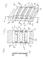
- a gas sensor 1 is shown, the primary for the measurement of oxygen is designed.
- the gas sensor 1 has a measuring chamber 2 in which an oxygen partial pressure P2 prevails.
- the measuring chamber 2 is surrounded by a bridge-shaped contact element 3 made of carbon or conductive metal.
- the contact element 3 is with a temperature-resistant ceramic adhesive on a flat surface Platinum resistance element 4, the one at room temperature Resistance between one ohm and one kiloohm in particular 20 Ohm (PT 20).
- About the Supply lines 5 can measure the voltage drop on the one hand and, on the other hand, via an temporarily connected external one Voltage source the heating element a heating current are fed.
- the heating or measuring coil is with a broken line.
- Elements 6 made of zirconium dioxide (ZrO 2 ) are glued to the resistance element 4 on both sides of the contact element 3, so that the closed measuring chamber 2 with ion-permeable walls is formed.
- Catalyst material 7 platinum is applied to the elements 6 on the outside.
- Figure 2 shows a section through a gas sensor on the resistance element is glued on.
- the geometry is a side view of a in FIG Contact element 3 shown.
- the partial pressure P1 of a gas in a gas mixture, especially in air, is like a pump probe measured.
- the pump probe is used in a first Process step (heating phase) by power supply on Resistor element heated while in a second Process step (measuring phase) the temperature of the PT 20 by means of the voltage drop across the resistance element is measured.
- FIG. 4 shows the structure of a gas sensor which is produced using the screen printing process.
- six free-standing conductive elements 13 made of platinum paste are printed in two rows a three on a resistance element 12 in a first method step.
- two beam-shaped chamber walls 14 made of zirconium dioxide of the same thickness are printed between the conductive elements 13 and cured in the next step.
- elements made of O 2 permeable ceramic 15 are introduced onto the free sides of the chamber walls 14 and into the free spaces.
- the structure is covered with a cover layer 16 made of O 2 impermeable ceramic.
- a method for Determination of the partial pressure of a gas in a Carry out gas mixture especially in air. This will over the resistance element 4 attached to the measuring chamber during a first operating phase (measuring phase) of the Voltage drop measured. In a second operating phase (Heating phase) then a voltage on the resistance element 4 applied so that a current flows that the gas sensor (1) heated. Thus, the resistance element 4 becomes both Measuring the temperature as well as for heating the gas sensor used.
Landscapes
- Chemical & Material Sciences (AREA)
- Life Sciences & Earth Sciences (AREA)
- Health & Medical Sciences (AREA)
- Biochemistry (AREA)
- Chemical Kinetics & Catalysis (AREA)
- Electrochemistry (AREA)
- Physics & Mathematics (AREA)
- Analytical Chemistry (AREA)
- Molecular Biology (AREA)
- General Health & Medical Sciences (AREA)
- General Physics & Mathematics (AREA)
- Immunology (AREA)
- Pathology (AREA)
- Investigating Or Analyzing Materials By The Use Of Electric Means (AREA)
- Investigating Or Analyzing Materials By The Use Of Fluid Adsorption Or Reactions (AREA)
- Measuring Oxygen Concentration In Cells (AREA)
Description
- Fig. 1
- einen Gassensor mit mehreren auf ein Widerstandselement aufgeklebten Kammerelementen,
- Fig. 2
- einen Schnitt durch einen Gassensor und
- Fig. 3
- ein Kontaktelement.
- Fig. 4
- einen im Siebdruckverfahren hergestellten Gassensor.
Claims (9)
- Gassensor (1) zur Bestimmung des Partialdrucks eines Gases in einem Gasgemisch, insbesondere in Luft, aufweisend eine Meßkammer (2) und aufweisend ein Widerstandselement (4), das zur Messung der Temperatur der Messkammer und zum Heizen der Messkammer dient, wobei das Widerstandselement (4) zeitweise an eine externe Spannungsquelle anschließbar ist, die dem Widerstandselement (4) einen Heizstrom zuführt,
dadurch gekennzeichnet, dass
die Meßkammer (2) nebeneinander angeordnete Kammerelemente (3,6) aufweist, die auf das Widerstandselement (4) aufgebracht sind, wobei ein mittleres der Kammerelemente von einem brückenförmigen Kontaktelement (3) gebildet ist, das die Meßkammer (2) über dem Widerstandselement (4) überspannt, wobei die zu beiden Seiten des Kontaktelementes (3) aufgebrachten Elemente (6) ionenpermeable Wände der Messkammer (2) bilden, wobei an die ionenpermeable Wände (6) jeweils ein brückenförmiges äußeres Kontaktelement (3a) angrenzt, wobei die Messkammer durch das Widerstandselement (4), das Kontaktelement (3) und die ionenpermeablen Wände abgeschlossen ist und wobei an die beiden äußeren Kontaktelemente (3a) jeweils ein abschließendes Keramikelement (4) angrenzt. - Gassensor nach Anspruch 1,
dadurch gekennzeichnet, dass das Widerstandselement (4) bei Zimmertemperatur einen Widerstand zwischen einem Ohm und einem Kiloohm hat. - Gassensor nach Anspruch 2,
dadurch gekennzeichnet, dass das Widerstandselement (4) ein Platinwiderstandselement (PT 20) ist, das einen Widerstand von etwa 20 Ohm bei Zimmertemperatur aufweist. - Gassensor nach einem der vorherigen Ansprüche,
dadurch gekennzeichnet, dass die Kammerelemente auf das Widerstandselement (4) aufgeklebt sind. - Gassensor nach einem der vorherigen Ansprüche,
dadurch gekennzeichnet, dass das Widerstandselement (4) im Siebdruckverfahren auf die Wandung der Meßkammer (2) oder die Kammerelemente (13,14,15,16) im Siebdruckverfahren auf das Widerstandselement (12) aufgedruckt sind. - Gassensor nach einem der vorherigen Ansprüche,
dadurch gekennzeichnet, dass das Widerstandselement (4) insbesondere mit Platin auf die Wandung der Meßkammer aufgedampft ist. - Gassensor nach einem der vorherigen Ansprüche,
dadurch gekennzeichnet , dass das Keramikelement (4) quaderförmig ist. - Gassensor nach einem der vorherigen Ansprüche,
dadurch gekennzeichnet, dass die ionenpermeablen Wände (6) von quaderförmigen Zirkondioxydelementen gebildet sind. - Gassensor nach Anspruch 8,
dadurch gekennzeichnet, dass das Kontaktelement (3) von den Zirkondioxydelementen (6) eingeschlossen und damit abgedichtet ist.
Applications Claiming Priority (2)
| Application Number | Priority Date | Filing Date | Title |
|---|---|---|---|
| DE19651328A DE19651328B4 (de) | 1996-12-11 | 1996-12-11 | Gassensor |
| DE19651328 | 1996-12-11 |
Publications (2)
| Publication Number | Publication Date |
|---|---|
| EP0848249A1 EP0848249A1 (de) | 1998-06-17 |
| EP0848249B1 true EP0848249B1 (de) | 2004-07-07 |
Family
ID=7814261
Family Applications (1)
| Application Number | Title | Priority Date | Filing Date |
|---|---|---|---|
| EP97121648A Expired - Lifetime EP0848249B1 (de) | 1996-12-11 | 1997-12-09 | Temperaturregelung für Gassensoren |
Country Status (3)
| Country | Link |
|---|---|
| EP (1) | EP0848249B1 (de) |
| AT (1) | ATE270776T1 (de) |
| DE (2) | DE19651328B4 (de) |
Families Citing this family (3)
| Publication number | Priority date | Publication date | Assignee | Title |
|---|---|---|---|---|
| DE19846487C5 (de) | 1998-10-09 | 2004-12-30 | Basf Ag | Meßsonde für die Detektion der Momentankonzentrationen mehrerer Gasbestandteile eines Gases |
| DE102007048049A1 (de) | 2007-10-05 | 2009-04-16 | Heraeus Sensor Technology Gmbh | Verwendung eines Ionenleiters für einen Gassensor |
| DE102013210903A1 (de) | 2013-06-11 | 2014-12-11 | Heraeus Sensor Technology Gmbh | Gassensor zur Messung unterschiedlicher Gase und dazugehöriges Herstellungsverfahren |
Family Cites Families (12)
| Publication number | Priority date | Publication date | Assignee | Title |
|---|---|---|---|---|
| NL7906833A (nl) * | 1979-09-13 | 1981-03-17 | Philips Nv | Gasanalyseapparaat. |
| US4500412A (en) * | 1981-08-07 | 1985-02-19 | Kabushiki Kaisha Toyota Chuo Kenkyusho | Oxygen sensor with heater |
| JPS59163556A (ja) * | 1983-03-08 | 1984-09-14 | Nippon Denso Co Ltd | 酸素濃度検出装置 |
| JPS60164241A (ja) * | 1984-02-06 | 1985-08-27 | Nippon Denso Co Ltd | 酸素濃度センサ用ヒ−タの制御装置 |
| DD268370A3 (de) * | 1986-06-02 | 1989-05-31 | Karl Marx Stadt Energie | Gasmeßfühler nach dem Wärmetönungsprinzip |
| DE8709786U1 (de) * | 1987-07-16 | 1987-09-10 | Conducta Gesellschaft für Meß- und Regeltechnik mbH & Co, 7016 Gerlingen | Multikombinationselektrode mit einem Temperaturfühler |
| US4953387A (en) * | 1989-07-31 | 1990-09-04 | The Regents Of The University Of Michigan | Ultrathin-film gas detector |
| DE4001048A1 (de) * | 1990-01-16 | 1991-07-18 | Draegerwerk Ag | Sensor fuer die gasmessung mit einem katalysatorfuehlerelement |
| DE4037528A1 (de) * | 1990-11-26 | 1992-05-27 | Energieversorgung Suedsachsen | Verfahren zur herstellung eines metalloxid-gassensors in hybridtechnik |
| CH684852A5 (de) * | 1991-06-07 | 1995-01-13 | Mettler Toledo Ag | Temperaturfühler für potentiometrische Messketten und Verfahren zu seiner Herstellung. |
| DE19515065A1 (de) * | 1995-04-27 | 1996-02-01 | Kurt Schwabe Inst Fuer Mes Und | Elektrochemischer Gassensor |
| DE19522347C1 (de) * | 1995-06-20 | 1996-09-19 | Siemens Ag | Verfahren und Anordnung zur Stabilisierung der Temperatur eines Heizelementes für einen Gassensor |
-
1996
- 1996-12-11 DE DE19651328A patent/DE19651328B4/de not_active Expired - Fee Related
-
1997
- 1997-12-09 DE DE59711765T patent/DE59711765D1/de not_active Expired - Lifetime
- 1997-12-09 AT AT97121648T patent/ATE270776T1/de not_active IP Right Cessation
- 1997-12-09 EP EP97121648A patent/EP0848249B1/de not_active Expired - Lifetime
Also Published As
| Publication number | Publication date |
|---|---|
| DE19651328B4 (de) | 2007-07-26 |
| DE19651328A1 (de) | 1998-06-18 |
| DE59711765D1 (de) | 2004-08-12 |
| ATE270776T1 (de) | 2004-07-15 |
| EP0848249A1 (de) | 1998-06-17 |
Similar Documents
| Publication | Publication Date | Title |
|---|---|---|
| DE4025715C1 (de) | ||
| DE4037740C2 (de) | ||
| DE4445243A1 (de) | Temperaturfühler | |
| DE2826515C2 (de) | ||
| EP0781409B1 (de) | Chemischer sensor | |
| DE68905993T2 (de) | Temperaturkompensierte, resistive sonde zum messen von konzentrationen von reaktiven fluid-sorten. | |
| DE10011562C2 (de) | Gassensor | |
| DE69409138T2 (de) | Sensor für brennbare Gase | |
| DE2658273B2 (de) | Gasdetektor | |
| EP0464244B1 (de) | Sensor zur Erfassung reduzierender Gase | |
| EP0464243B1 (de) | Sauerstoffsensor mit halbleitendem Galliumoxid | |
| DE19929625A1 (de) | Stickoxidgassensor | |
| WO2018210571A1 (de) | Sensor zur bestimmung von gasparametern | |
| DE19806110C2 (de) | Verfahren zur Ermittlung der Abgastemperatur und der Luft/Kraftstoff-Verhältniszahl Lambda und Sensoranordnung zur Durchführung des Verfahrens | |
| DE4006085A1 (de) | Sensor zur gleichzeitigen bestimmung der zusammensetzung von gasgemischen und der gasgeschwindigkeit | |
| EP0908721A1 (de) | Verfahren zur Ermittlung der Abgastemperatur und der Luft/Kraftstoff-Verhältniszahl Lambda und Sensoranordnung zur Durchführung des Verfahrens | |
| DE19910444C2 (de) | Temperaturfühler | |
| EP0377792A1 (de) | Sensor zur Bestimmung der Gaskonzentration in einem Gasgemisch durch Messung der Wärmetönung | |
| EP0104636A2 (de) | Sauerstoffsensor und Verfahren zu dessen Herstellung | |
| WO2000062056A1 (de) | Halbleiter-gassensor mit gehäuse und verfahren zur messung von gaskonzentrationen | |
| DE3446277A1 (de) | Messwertaufnehmer zur messung des taupunkts | |
| DE19651328B4 (de) | Gassensor | |
| DE102004034192A1 (de) | Hochtemperaturstabiler Sensor | |
| EP0649018B1 (de) | Vorrichtung zum kontinuierlichen Überwachen der Konzentrationen von gasförmigen Bestandteilen in Gasgemischen | |
| EP0987545A1 (de) | Röhrchenförmiger Gassensor mit aufgedruckten Sensor- und Heizflächen |
Legal Events
| Date | Code | Title | Description |
|---|---|---|---|
| PUAI | Public reference made under article 153(3) epc to a published international application that has entered the european phase |
Free format text: ORIGINAL CODE: 0009012 |
|
| AK | Designated contracting states |
Kind code of ref document: A1 Designated state(s): AT BE CH DE DK ES FI FR GB GR IE IT LI LU MC NL PT SE |
|
| AX | Request for extension of the european patent |
Free format text: LT;LV;RO;SI |
|
| 17P | Request for examination filed |
Effective date: 19981216 |
|
| AKX | Designation fees paid |
Free format text: AT BE CH DE DK ES FI FR GB GR IE IT LI LU MC NL PT SE |
|
| RBV | Designated contracting states (corrected) |
Designated state(s): AT BE CH DE DK ES FI FR GB GR IE IT LI LU MC NL PT SE |
|
| 17Q | First examination report despatched |
Effective date: 20020918 |
|
| RAP1 | Party data changed (applicant data changed or rights of an application transferred) |
Owner name: JUERGEN DITTRICH ELEKTRONIK |
|
| GRAP | Despatch of communication of intention to grant a patent |
Free format text: ORIGINAL CODE: EPIDOSNIGR1 |
|
| GRAS | Grant fee paid |
Free format text: ORIGINAL CODE: EPIDOSNIGR3 |
|
| GRAA | (expected) grant |
Free format text: ORIGINAL CODE: 0009210 |
|
| AK | Designated contracting states |
Kind code of ref document: B1 Designated state(s): AT BE CH DE DK ES FI FR GB GR IE IT LI LU MC NL PT SE |
|
| PG25 | Lapsed in a contracting state [announced via postgrant information from national office to epo] |
Ref country code: NL Free format text: LAPSE BECAUSE OF FAILURE TO SUBMIT A TRANSLATION OF THE DESCRIPTION OR TO PAY THE FEE WITHIN THE PRESCRIBED TIME-LIMIT Effective date: 20040707 Ref country code: IT Free format text: LAPSE BECAUSE OF FAILURE TO SUBMIT A TRANSLATION OF THE DESCRIPTION OR TO PAY THE FEE WITHIN THE PRESCRIBED TIME-LIMIT;WARNING: LAPSES OF ITALIAN PATENTS WITH EFFECTIVE DATE BEFORE 2007 MAY HAVE OCCURRED AT ANY TIME BEFORE 2007. THE CORRECT EFFECTIVE DATE MAY BE DIFFERENT FROM THE ONE RECORDED. Effective date: 20040707 Ref country code: IE Free format text: LAPSE BECAUSE OF FAILURE TO SUBMIT A TRANSLATION OF THE DESCRIPTION OR TO PAY THE FEE WITHIN THE PRESCRIBED TIME-LIMIT Effective date: 20040707 Ref country code: FI Free format text: LAPSE BECAUSE OF FAILURE TO SUBMIT A TRANSLATION OF THE DESCRIPTION OR TO PAY THE FEE WITHIN THE PRESCRIBED TIME-LIMIT Effective date: 20040707 |
|
| REG | Reference to a national code |
Ref country code: GB Ref legal event code: FG4D Free format text: NOT ENGLISH |
|
| REG | Reference to a national code |
Ref country code: CH Ref legal event code: EP |
|
| REG | Reference to a national code |
Ref country code: IE Ref legal event code: FG4D Free format text: GERMAN |
|
| REF | Corresponds to: |
Ref document number: 59711765 Country of ref document: DE Date of ref document: 20040812 Kind code of ref document: P |
|
| PG25 | Lapsed in a contracting state [announced via postgrant information from national office to epo] |
Ref country code: SE Free format text: LAPSE BECAUSE OF FAILURE TO SUBMIT A TRANSLATION OF THE DESCRIPTION OR TO PAY THE FEE WITHIN THE PRESCRIBED TIME-LIMIT Effective date: 20041007 Ref country code: GR Free format text: LAPSE BECAUSE OF FAILURE TO SUBMIT A TRANSLATION OF THE DESCRIPTION OR TO PAY THE FEE WITHIN THE PRESCRIBED TIME-LIMIT Effective date: 20041007 Ref country code: DK Free format text: LAPSE BECAUSE OF FAILURE TO SUBMIT A TRANSLATION OF THE DESCRIPTION OR TO PAY THE FEE WITHIN THE PRESCRIBED TIME-LIMIT Effective date: 20041007 |
|
| PG25 | Lapsed in a contracting state [announced via postgrant information from national office to epo] |
Ref country code: ES Free format text: LAPSE BECAUSE OF FAILURE TO SUBMIT A TRANSLATION OF THE DESCRIPTION OR TO PAY THE FEE WITHIN THE PRESCRIBED TIME-LIMIT Effective date: 20041018 |
|
| GBT | Gb: translation of ep patent filed (gb section 77(6)(a)/1977) | ||
| PG25 | Lapsed in a contracting state [announced via postgrant information from national office to epo] |
Ref country code: LU Free format text: LAPSE BECAUSE OF NON-PAYMENT OF DUE FEES Effective date: 20041209 Ref country code: AT Free format text: LAPSE BECAUSE OF NON-PAYMENT OF DUE FEES Effective date: 20041209 |
|
| PG25 | Lapsed in a contracting state [announced via postgrant information from national office to epo] |
Ref country code: MC Free format text: LAPSE BECAUSE OF NON-PAYMENT OF DUE FEES Effective date: 20041231 Ref country code: LI Free format text: LAPSE BECAUSE OF NON-PAYMENT OF DUE FEES Effective date: 20041231 Ref country code: CH Free format text: LAPSE BECAUSE OF NON-PAYMENT OF DUE FEES Effective date: 20041231 Ref country code: BE Free format text: LAPSE BECAUSE OF NON-PAYMENT OF DUE FEES Effective date: 20041231 |
|
| NLV1 | Nl: lapsed or annulled due to failure to fulfill the requirements of art. 29p and 29m of the patents act | ||
| REG | Reference to a national code |
Ref country code: IE Ref legal event code: FD4D |
|
| PLBE | No opposition filed within time limit |
Free format text: ORIGINAL CODE: 0009261 |
|
| STAA | Information on the status of an ep patent application or granted ep patent |
Free format text: STATUS: NO OPPOSITION FILED WITHIN TIME LIMIT |
|
| ET | Fr: translation filed | ||
| 26N | No opposition filed |
Effective date: 20050408 |
|
| BERE | Be: lapsed |
Owner name: *JURGEN DITTRICH ELEKTRONIK Effective date: 20041231 |
|
| REG | Reference to a national code |
Ref country code: CH Ref legal event code: PL |
|
| BERE | Be: lapsed |
Owner name: *JURGEN DITTRICH ELEKTRONIK Effective date: 20041231 |
|
| PG25 | Lapsed in a contracting state [announced via postgrant information from national office to epo] |
Ref country code: PT Free format text: LAPSE BECAUSE OF NON-PAYMENT OF DUE FEES Effective date: 20041207 |
|
| PGFP | Annual fee paid to national office [announced via postgrant information from national office to epo] |
Ref country code: FR Payment date: 20081216 Year of fee payment: 12 |
|
| PGFP | Annual fee paid to national office [announced via postgrant information from national office to epo] |
Ref country code: GB Payment date: 20081219 Year of fee payment: 12 |
|
| GBPC | Gb: european patent ceased through non-payment of renewal fee |
Effective date: 20091209 |
|
| REG | Reference to a national code |
Ref country code: FR Ref legal event code: ST Effective date: 20100831 |
|
| PG25 | Lapsed in a contracting state [announced via postgrant information from national office to epo] |
Ref country code: FR Free format text: LAPSE BECAUSE OF NON-PAYMENT OF DUE FEES Effective date: 20091231 |
|
| PG25 | Lapsed in a contracting state [announced via postgrant information from national office to epo] |
Ref country code: GB Free format text: LAPSE BECAUSE OF NON-PAYMENT OF DUE FEES Effective date: 20091209 |
|
| PGFP | Annual fee paid to national office [announced via postgrant information from national office to epo] |
Ref country code: DE Payment date: 20111229 Year of fee payment: 15 |
|
| REG | Reference to a national code |
Ref country code: DE Ref legal event code: R119 Ref document number: 59711765 Country of ref document: DE Effective date: 20130702 |
|
| PG25 | Lapsed in a contracting state [announced via postgrant information from national office to epo] |
Ref country code: DE Free format text: LAPSE BECAUSE OF NON-PAYMENT OF DUE FEES Effective date: 20130702 |