EP0848127A1 - Klemm-Befestigungsvorrichtung für Beschlagteile - Google Patents
Klemm-Befestigungsvorrichtung für Beschlagteile Download PDFInfo
- Publication number
- EP0848127A1 EP0848127A1 EP97115234A EP97115234A EP0848127A1 EP 0848127 A1 EP0848127 A1 EP 0848127A1 EP 97115234 A EP97115234 A EP 97115234A EP 97115234 A EP97115234 A EP 97115234A EP 0848127 A1 EP0848127 A1 EP 0848127A1
- Authority
- EP
- European Patent Office
- Prior art keywords
- claws
- longitudinal
- base
- fastening device
- support plate
- Prior art date
- Legal status (The legal status is an assumption and is not a legal conclusion. Google has not performed a legal analysis and makes no representation as to the accuracy of the status listed.)
- Granted
Links
Images


Classifications
-
- E—FIXED CONSTRUCTIONS
- E05—LOCKS; KEYS; WINDOW OR DOOR FITTINGS; SAFES
- E05C—BOLTS OR FASTENING DEVICES FOR WINGS, SPECIALLY FOR DOORS OR WINDOWS
- E05C9/00—Arrangements of simultaneously actuated bolts or other securing devices at well-separated positions on the same wing
- E05C9/004—Faceplates ; Fixing the faceplates to the wing
Definitions
- the invention relates to a clamp fastening device for Fitting parts in both sides with undercut areas provided longitudinal grooves or channels of metal or Plastic profiles, especially hollow profiles on window and Door frames or sashes, in which the hardware parts with a Base through a longitudinal opening or a longitudinal gap between the undercut areas in the longitudinal grooves or channels are retractable transversely to their longitudinal direction, in which the Base in its sinking direction on the bottom of the longitudinal grooves or channels and / or before their longitudinal opening or longitudinal gap rigid on the outer surfaces of the metal or plastic profiles is supported, and in the anchoring claws from the base sideways into the undercut areas of the longitudinal grooves or channels can be spread as well as by tightening Tendons, e.g. Screws that can be fixed.
- Tendons e.g. Screws that can be fixed.
- a generic clamp fastening device for one so-called faceplate fitting is known by the EP-B1-0 056 484.
- faceplate attached as a base U-shaped holder.
- Their Side legs have resilient tongues, which the Undercut areas snap automatically can reach behind after inserting the base through the longitudinal opening or the longitudinal gap of the longitudinal grooves or channels spring back.
- Anchoring projections should also be in the ground of the longitudinal grooves or channels of metal or Intervene in plastic profiles.
- the invention aims to provide a clamp fastening device of the genus initially specified from which, with high functional reliability, also an optimal and Anchoring effect unaffected by manufacturing tolerances for the fittings on the metal or plastic profiles can be expected.
- a clamp fastening device has proven to be particularly advantageous proven in the invention
- Base of the fitting part designed longitudinally symmetrical as well essentially on both sides of its longitudinal plane of symmetry outward facing support and guide surfaces for a Pair of claws is equipped that the support plate also executed longitudinally symmetrically and with Abutment troughs for each claw of the pair of claws is equipped and that the tendons between the base and Support plate also effective on the longitudinal plane of symmetry are.
- Such a clamp fastening device works with her Pair of pressure pads, so to speak, in the manner of a Expansion anchor on which the extent of the spread and thus also the anchoring force over the tendons is appropriate can be varied.
- the base also turned out to be recommended and the support plate of the fitting part also one to give transverse symmetrical design and on both sides of the To provide a pair of claws each across the transverse plane of symmetry, while as a central tendon for both pairs of claws a screw in the intersection of the plane of longitudinal symmetry and cross-symmetry plane between base and support plate is effective.
- a single tendon does it in this If possible, relatively large anchoring areas at the same time to bring effect and thereby a secure hold of the To ensure fitting part.
- a space-saving design of the clamp fastening device can be created if the support plate for the Pair of pressure claws on the fitting part in a window of the Pedestal each guided by lugs engaging in grooves is located on the transverse edges of the window and the support plate are located.
- the screw provided as a tendon can on the Bottom of the longitudinal grooves or channels in the metal or Plastic profile facing end of a cone tip have, which in the bottom of the longitudinal groove or the longitudinal channel is collectible.
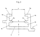
- Fig. 1 of the drawing is - on an enlarged scale - from a metal or plastic hollow profile 1 as it usually for the construction of window and door frames or - wing is used, only that Cross-sectional section shown, which for accommodation and / or fastening fittings with a longitudinal groove or a longitudinal channel 2 is equipped.
- This longitudinal groove or this longitudinal channel 2 has a longitudinal opening or a longitudinal gap 3.
- she or he is with undercut areas 4a and / or 4b on both sides provided, their cross-sectional shape and dimensions each is determined by profile webs 5a and / or 5b.
- Profile webs 5a directly the longitudinal opening or Limit the longitudinal gap 3 of the longitudinal groove or the longitudinal channel 2
- the two lateral boundaries of the longitudinal groove or the longitudinal channel 2 are mirror images of themselves opposite, approximately F-shaped profile pieces educated.
- the fitting part 7 has a base 8 through which Longitudinal opening or the longitudinal gap 3 and the constriction area 6, ie between the undercut areas 4a and 4b of the F-shaped profile pieces in the longitudinal groove or Longitudinal channel 2 can be sunk (Fig. 3). It can either the base 8 in the direction of its underside on the bottom 9 of the longitudinal groove or the longitudinal channel 2 support. But it can also the fitting part 7 with a shoulder 10 supporting the longitudinal opening or the Longitudinal gap 3 against the outer surfaces of the F-shaped Profile pieces of the metal or plastic hollow profile 1 create, as can be seen from FIGS. 4 to 9.
- each fitting part 7 For the purpose of fixing it to the metal or plastic hollow profile 1 or for anchoring in its longitudinal groove or Longitudinal channel 2 is each fitting part 7 with a special one Clamp fastening device 11 equipped.
- the pressure claws 12 on the one hand in a free space in the base 8 can be moved obliquely outwards, namely slidably guided and held.
- your abutment on one in the free space of the base 8 guided support plate 13, which via a tendon 14, preferably a screw on the base 8 against the Printing claws 12 is held adjustable.
- the clamp fastening device 11 For the insertion of the fitting parts 7 in the longitudinal groove or the longitudinal channel 2 of the metal or plastic hollow profile 1 is the clamp fastening device 11 initially 4 to 6 corresponding basic or Starting position.
- the Fitting part 7 becomes the clamping fastening device 11 however, from this FIGS. 4 to 6 basic or Starting position in the removable from FIGS. 7 to 9 Brought active position.
- the 12th anchoring claws carried out sideways from the base 8 pushed out. They push themselves with their free ones Ends below the profile webs 5b in the opposite direction Directions in the two undercut areas 4b of the Longitudinal groove or the longitudinal channel 2, as that of FIGS. 7 to 9 can be clearly seen.
- the drawing also shows that at least the Base 8 of the fitting part 7 to a level 15-15 is designed longitudinally symmetrical. On both sides of its longitudinal plane of symmetry 15-15 is the base 8 with in essentially outward support and Guide surfaces 16 for a pair of claws 12 Is provided.
- the support plate 13 is to level 15-15 designed longitudinally symmetrical and with abutment troughs 17 for each claw 12 of the pair of claws equipped.
- the tendon 14 used screw between the base 8 and the support plate 13 is also effective on the plane of symmetry 15-15 and engages there in a threaded bore 18 of the base 8.
- the back surfaces facing the longitudinal plane of symmetry 15-15 19 of the claws 12 of each pair of claws and also that these in the base 8 associated support and guide surfaces 16th preferably have an approximately complementary relationship arched contour.
- the back surfaces have 19 of the claws 12 has a convex curvature, while the Support and guide surfaces 16 in the free space of the base 8 a have concave curvature.
- FIGS. 2, 3 and 10 but also remove that used as tendon 14 Screw at the intersection of longitudinal plane of symmetry 15-15 and Transverse plane of symmetry 22-22 between the base 8 and the Support plate 13 of the fitting part 7 is effective.
- Both pairs of claws with their loops or brackets 20 and their intermediate webs 23 can be advantageous Way as an injection molded plastic part, but if necessary also produce as a die-cast molded part made of metal.
- the one used as a tendon 14 Screw on her the bottom 9 of the longitudinal groove or End facing a longitudinal channel 2 a cone tip 27 exhibit. Because when screwing in the screw Threaded bore 18 of the base 8 this cone tip 27 on the Bottom 9 moves, it can ultimately penetrate into this and an additional locking device for the fitting part 7 form, as is FIGS. 3 and 9 of the drawing can be removed.
- clamp fastening device 11 is particularly special advantageously applicable if that with her equipped fitting part 7, the bearing and guide plate for a so-called folding lever gear forms how it for Actuation of the locking bars for the tucking wing of double-leaf windows or doors without intermediate frames is needed.
Abstract
Description
- Fig. 1
- in vergrößertem Maßstab ein Querschnittsteilstück aus einem zum Bau von Fenster- und Türrahmen oder - flügeln geeigneten Metall- oder Kunststoff-Hohlprofil, das für den Einbau von Beschlagteilen Längsnuten oder -kanäle mit beidseitigen Hinterschneidungsbereichen aufweist,
- Fig. 2
- in Längsschnitt ein Beschlagteil, das in die Längsnuten des aus Fig. 1 ersichtlichen Querschnittsteilstücks einsetzbar ist,
- Fig. 3
- eine der Fig. 2 entsprechende Darstellung des in den Längsnuten eines Querschnittsteilstück nach Fig. 1 verankerten Beschlagteils,
- Fig. 4
- einen Schnitt entlang der Linie IV-IV durch das Beschlagteil nach Fig. 2 in seiner in eine Längsnut oder einen Längskanal eingesetzten Grund- bzw. Ausgangsstellung,
- Fig. 5
- einen Schnitt entlang der Linie V-V durch das Beschlagteil nach Fig. 2,
- Fig. 6
- einen Schnitt entlang der Linie VI-VI durch das Beschlagteil nach Fig. 2,
- Fig. 7
- einen der Fig. 4 entsprechenden Schnitt, wobei jedoch das Beschlagteil seinen der Fig. 3 entsprechnden verankerten Zustand hat,
- Fig. 8
- einen der Fig. 5 entsprechenden Schnitt durch das verankerte Beschlagteil,
- Fig. 9
- einen der Fig. 6 entsprechenden Schnitt durch das verankerte Beschlagteil, und
- Fig. 10
- die Einbau-Anordnung des Beschlagteils nach Fig. 3 in der Draufsicht.
- 1
- Metall- oder Kunststoff-Hohlprofil
- 2
- Längsnut/ Längskanal
- 3
- Längsöffnung/ Längsspalt
- 4a, 4b
- Hinterschneidungsbereiche
- 5a, 5b
- Profilstege
- 6
- Verengungsbereich
- 7
- Beschlagteil
- 8
- Sockel
- 9
- Boden
- 10
- Schulter
- 11
- Klemm-Befestigungsvorrichtung
- 12
- Druckpratzen
- 13
- Stützplatte
- 14
- Spannglied/ Schraube
- 15-15
- Längs-Symmetrieebene
- 16
- Stütz- und Führungsflächen
- 17
- Widerlagermulde
- 18
- Gewindebohrung
- 19
- Rückenfläche
- 20
- Schlaufe/ Bügel
- 21
- Öffnung/ Durchlaß
- 22-22
- Quer-Symmetrieebene
- 23
- Zwischensteg
- 24
- Fenster
- 25
- Nut
- 26
- Nase
- 27
- Kegelspitze
Claims (10)
- Klemm-Befestigungsvorrichtung (11) für Beschlagteile (7) in beidseitig mit Hinterschneidungsbereichen (4a, 4b) versehenen Längsnuten oder -kanälen (2) von Metall- oder Kunststoffprofilen (1), insbesondere Hohlprofilen an Fenster- und Türrahmen oder -flügeln,
bei der die Beschlagteile (7) mit einem Sockel (8) durch eine Längsöffnung bzw. einen Längsspalt (3) zwischen den Hinterschneidungsbereichen (4a, 4b) in die Längsnuten oder -kanäle (2) quer zu deren Längsrichtung einsenkbar sind, bei der der Sockel (8) in seiner Einsenkrichtung auf dem Boden (9) der Längsnuten oder -kanäle (2) oder vor deren Langsöffnung bzw. Längsspalt (3) am Außenflächen der Metall- oder Kunststoffprofile (1) starr abstütztbar ist, und bei der vom Sockel (8) her Verankerungsklauen (12) seitwärts in die Hinterschneidungsbereiche (4b) der Längsnuten oder Kanäle (2) einspreizbar sowie darin durch Anziehen von Spanngliedern (14), z.B. Schrauben, fixierbar sind,
dadurch gekennzeichnet,daß im Sockel (8) als Verankerungsklauen in sich starre Druckpratzen (12) schräg nach auswärts gleitfähig geführt und gehalten (16, 19) sind,daß die Druckpratzen (12) ihr Widerlager an einer im Sockel (8) geführten Stützplatte (13) haben,und daß die Stützplatte (13) über die Spannglieder (14) relativ zum Sockel (8) gegen die Druckpratzen (12) anstellbar gehalten ist. - Klemm-Befestigungsvorrichtung nach Anspruch 1,
dadurch gekennzeichnet,daß der Sockel (8) des Beschlagteils (7) längssymmetrisch gestaltet sowie beidseitig seiner Längs-Symmetrieebene (15-15) mit im wesentlichen nach auswärts gerichteten Stütz- und Führungsflächen (16) für ein Paar von Druckpratzen (12) ausgestattet ist,daß die Stützplatte (13) ebenfalls längssymmetrisch ausgeführt und mit Widerlagermulden (17) für jede Druckpratze (12) des Druckpratzen-Paares ausgestattet ist,und daß die Spannglieder (14) zwischen Sockel (8) und Stützplatte (13) ebenfalls auf der Längs-Symmetrieebene (15-15) wirksam sind. - Klemm-Befestigungsvorrichtung nach einem der Ansprüche 1 und 2,
dadurch gekennzeichnet,daß die der Längs-Symmetrieebene (15-15) zugewendeten Rückenflächen (19) der Druckpratzen (12) und - vorzugsweise - auch die ihnen im Sockel (8) zugeordneten Stütz- und Führungsflächen (16) zueinander etwa komplementär bogenförmig konturiert sind, wobei die Rückenflächen (19) der Druckpratzen (12) konvex, die Stütz- und Führungsflächen (16) des Sockels (8) aber konkav gewölbt verlaufen. - Klemm-Befestigungsvorrichtung nach einem der Ansprüche 1 bis 3,
dadurch gekennzeichnet,daß die beiden Druckpratzen (12) jedes Druckpratzen-Paares an ihrem oberen Ende durch eine Schlaufe oder einen Bügel (20) in Verbindung stehen, die bzw. der eine Öffnung bzw. einen Durchlaß (21) der Stützplatte (13) durchgreift. - Klemm-Befestigungsvorrichtung nach einem der Ansprüche 1 bis 4,
dadurch gekennzeichnet,daß Sockel (8) und Stützplatte (13) des Beschlagteils (7) auch eine quersymmetrische Ausgestaltung haben und beidseitig der Quer-Symmetrieebene (22-22) je ein Druckpratzen-Paar vorgesehen ist (Fig. 2 und 3), während als eine zentrales Spannglied (14) eine Schraube im Schnittpunkt von Längs-Symmetrieebene (15-15) und Quer-Symmetrieebene (22-22) zwischen Sockel (8) und Stützplatte (13) wirksam ist (Fig. 10). - Klemm-Befestigungsvorrichtung nach einem der Ansprüche 1 bis 5,
dadurch gekennzeichnet,daß die auf der gleichen Seite der Längs-Symmetrieebene (15-15) liegenden Druckpratzen (12) der beiden Druckpratzen-Paare je durch einen Zwischensteg (23) miteinander in Verbindung stehen (Fig. 6 und 9). - Klemm-Befestigungsvorrichtung nach einem der Ansprüche 1 bis 6,
dadurch gekennzeichnet,daß alle Druckpratzen-Paare mit ihren Schlaufen bzw. Bügeln (20) und Zwischenstegen (23) als ein Spritzguß-Formteil aus Kunststoff oder als ein Druckguß-Formteil aus Metall ausgebildet sind. - Klemm-Befestigungsvorrichtung nach einem der Ansprüche 1 bis 7,
dadurch gekennzeichnet,daß die Stützplatte (13) für die Druckpratzen-Paare am Beschlagteil (7) in einem Fenster (24) der Sockels (8) jeweils durch in Nuten (25) eingreifende Nasen (26) geführt ist, die sich an Querkanten des Fensters (24) und der Stützplatte (13) befinden (Fig. 10). - Klemm-Befestigungsvorrichtung nach einem der Ansprüche 1 bis 9,
dadurch gekennzeichnet,daß die als Spannglied (14) vorgesehene Schraube an ihrem dem Boden (9) der Längsnuten oder -kanäle (2) zugewendeten Ende eine Kegelspitze (27) aufweist, die in den Boden (9) der Längsnut bzw. des Längskanals (2) eintreibbar ist (Fig. 3 und 9). - Klemm-Befestigungsvorrichtung nach einem der Ansprüche 1 bis 9,
dadurch gekennzeichnet,daß das Beschlagteil (7) die Lager- und Führungsplatte eines Falz-Hebelgetriebes zur Betätigung der Riegelstangen für den unterschlagenden Flügel zweiflügeliger Fenster oder Türen ohne Rahmen-Zwischenpfosten bildet.
Applications Claiming Priority (2)
| Application Number | Priority Date | Filing Date | Title |
|---|---|---|---|
| DE29621561U DE29621561U1 (de) | 1996-12-12 | 1996-12-12 | Klemm-Befestigungsvorrichtung für Beschlagteile |
| DE29621561U | 1996-12-12 |
Publications (2)
| Publication Number | Publication Date |
|---|---|
| EP0848127A1 true EP0848127A1 (de) | 1998-06-17 |
| EP0848127B1 EP0848127B1 (de) | 2001-10-10 |
Family
ID=8033182
Family Applications (1)
| Application Number | Title | Priority Date | Filing Date |
|---|---|---|---|
| EP97115234A Expired - Lifetime EP0848127B1 (de) | 1996-12-12 | 1997-09-03 | Klemm-Befestigungsvorrichtung für Beschlagteile |
Country Status (5)
| Country | Link |
|---|---|
| EP (1) | EP0848127B1 (de) |
| AT (1) | ATE206795T1 (de) |
| DE (2) | DE29621561U1 (de) |
| DK (1) | DK0848127T3 (de) |
| ES (1) | ES2165552T3 (de) |
Cited By (1)
| Publication number | Priority date | Publication date | Assignee | Title |
|---|---|---|---|---|
| CN109158053A (zh) * | 2018-11-05 | 2019-01-08 | 西安建筑科技大学 | 一种自带导流通道的导流塞 |
Families Citing this family (2)
| Publication number | Priority date | Publication date | Assignee | Title |
|---|---|---|---|---|
| DE19923434B4 (de) * | 1999-05-21 | 2005-11-03 | Bayerwald Fenster-Türen Altenbuchinger GmbH & Co. KG | Vorrichtung zur Befestigung einer Beschlagleiste an einem Profil |
| FR3064292B1 (fr) * | 2017-03-23 | 2019-03-29 | Ferco | Ferrure de verrouillage, de type cremone ou similaire a encastrer |
Citations (7)
| Publication number | Priority date | Publication date | Assignee | Title |
|---|---|---|---|---|
| FR1572059A (de) * | 1967-07-19 | 1969-06-20 | ||
| FR2467276A3 (fr) * | 1979-10-11 | 1981-04-17 | Technal International Sa | Perfectionnements aux targettes, notamment pour montage sur feuillure de vantail |
| AT366755B (de) * | 1980-10-14 | 1982-05-10 | Lapp Finze Ag | Klemmeinrichtung zur befestigung von beschlaegeteilen |
| EP0056484A2 (de) * | 1981-01-17 | 1982-07-28 | SCHÜCO Heinz Schürmann GmbH & Co. | Mit einem Stulpschienenbeschlag ausgerüsteter Tür- oder Fensterflügel |
| DE3621811A1 (de) * | 1986-06-28 | 1988-01-07 | Dyna Plastik Gmbh | Schliessstueck fuer fenster und tueren |
| DE29508225U1 (de) * | 1995-05-18 | 1995-08-17 | Siegenia Frank Kg | Fenster oder Tür mit Schließstücken |
| DE29613816U1 (de) * | 1996-08-09 | 1996-09-26 | Siegenia Frank Kg | Falz-Hebelgetriebe für Fenster oder Türen |
-
1996
- 1996-12-12 DE DE29621561U patent/DE29621561U1/de not_active Expired - Lifetime
-
1997
- 1997-09-03 ES ES97115234T patent/ES2165552T3/es not_active Expired - Lifetime
- 1997-09-03 DE DE59704859T patent/DE59704859D1/de not_active Expired - Lifetime
- 1997-09-03 DK DK97115234T patent/DK0848127T3/da active
- 1997-09-03 EP EP97115234A patent/EP0848127B1/de not_active Expired - Lifetime
- 1997-09-03 AT AT97115234T patent/ATE206795T1/de not_active IP Right Cessation
Patent Citations (7)
| Publication number | Priority date | Publication date | Assignee | Title |
|---|---|---|---|---|
| FR1572059A (de) * | 1967-07-19 | 1969-06-20 | ||
| FR2467276A3 (fr) * | 1979-10-11 | 1981-04-17 | Technal International Sa | Perfectionnements aux targettes, notamment pour montage sur feuillure de vantail |
| AT366755B (de) * | 1980-10-14 | 1982-05-10 | Lapp Finze Ag | Klemmeinrichtung zur befestigung von beschlaegeteilen |
| EP0056484A2 (de) * | 1981-01-17 | 1982-07-28 | SCHÜCO Heinz Schürmann GmbH & Co. | Mit einem Stulpschienenbeschlag ausgerüsteter Tür- oder Fensterflügel |
| DE3621811A1 (de) * | 1986-06-28 | 1988-01-07 | Dyna Plastik Gmbh | Schliessstueck fuer fenster und tueren |
| DE29508225U1 (de) * | 1995-05-18 | 1995-08-17 | Siegenia Frank Kg | Fenster oder Tür mit Schließstücken |
| DE29613816U1 (de) * | 1996-08-09 | 1996-09-26 | Siegenia Frank Kg | Falz-Hebelgetriebe für Fenster oder Türen |
Cited By (1)
| Publication number | Priority date | Publication date | Assignee | Title |
|---|---|---|---|---|
| CN109158053A (zh) * | 2018-11-05 | 2019-01-08 | 西安建筑科技大学 | 一种自带导流通道的导流塞 |
Also Published As
| Publication number | Publication date |
|---|---|
| ES2165552T3 (es) | 2002-03-16 |
| DK0848127T3 (da) | 2001-11-19 |
| DE29621561U1 (de) | 1997-02-20 |
| ATE206795T1 (de) | 2001-10-15 |
| DE59704859D1 (de) | 2001-11-15 |
| EP0848127B1 (de) | 2001-10-10 |
Similar Documents
| Publication | Publication Date | Title |
|---|---|---|
| EP0056484B1 (de) | Mit einem Stulpschienenbeschlag ausgerüsteter Tür- oder Fensterflügel | |
| EP1020575B1 (de) | T-Verbindung zwischen einem Sprossen- und einem Pfostenprofil einer Fasade oder eines Lichtdaches | |
| DE102009012438B4 (de) | Pfostenverbinder | |
| WO1980001709A1 (fr) | Element de couplage pour supports ayant une rainure longitudinale a contre-depouille | |
| DE2614446A1 (de) | Scharnier | |
| EP1568838A2 (de) | Führungsschiene für Schiebe- oder Faltschiebetüren | |
| EP1501993B1 (de) | Anordnung mit türblatt und scharnieren sowie duschkabine | |
| DE202006004287U1 (de) | Keilvorrichtung | |
| DE3437430C1 (de) | Stoßverbindung eines Kämpferprofils mit einem Rahmen- oder Sprossenprofil für wärmegedämmte Fenster, Türen o.dgl. | |
| EP0848127B1 (de) | Klemm-Befestigungsvorrichtung für Beschlagteile | |
| DE2722758A1 (de) | Scharnier, insbesondere moebelscharnier | |
| DE3844486A1 (de) | Halteprofil fuer eine duschtrennwand | |
| DE102006012390A1 (de) | Keilvorrichtung | |
| DE19808847C2 (de) | Tür- oder Fensterbeschlag | |
| DE102007009667B4 (de) | Profilkonstruktion | |
| EP2085551A2 (de) | Führungsvorrichtung für einen Schiebeflügel | |
| DE102004054028A1 (de) | Vorrichtung zum Positionieren einer Tür | |
| DE202019000921U1 (de) | Halteanordnung, Dichtungsanordnung und Duschabtrennung | |
| DE4015742C2 (de) | Schließteil-Befestigung an Fenster- oder Türrahmen | |
| EP0006439B2 (de) | Vorrichtung zur Stossstellenüberlappung an Stulpschienen | |
| DE10354310A1 (de) | Dichtung insbesondere selbsttätig absenkende Bodendichtung für Türen | |
| DE3134162A1 (de) | Klemmeinrichtung zur befestigung von beschlaegeteilen | |
| DE10114083C1 (de) | Stoßverbindung eines Kämpferhohlprofils mit einem Rahmen- oder Sprossenprofil | |
| EP1518987B1 (de) | Fenster, Tür oder dergleichen mit einem Anbauteil mit Bauteilverankerung | |
| EP1038487B1 (de) | Duscheinrichtung mit einer Stütze und einer Befestigungseinrichtung für ein flaches Wandungselement |
Legal Events
| Date | Code | Title | Description |
|---|---|---|---|
| PUAI | Public reference made under article 153(3) epc to a published international application that has entered the european phase |
Free format text: ORIGINAL CODE: 0009012 |
|
| AK | Designated contracting states |
Kind code of ref document: A1 Designated state(s): AT BE CH DE DK ES FR GB IT LI NL |
|
| AX | Request for extension of the european patent |
Free format text: AL;LT;LV;RO;SI |
|
| 17P | Request for examination filed |
Effective date: 19980701 |
|
| AKX | Designation fees paid |
Free format text: AT BE CH DE DK ES FR GB IT LI NL |
|
| RBV | Designated contracting states (corrected) |
Designated state(s): AT BE CH DE DK ES FR GB IT LI NL |
|
| 17Q | First examination report despatched |
Effective date: 20000731 |
|
| GRAG | Despatch of communication of intention to grant |
Free format text: ORIGINAL CODE: EPIDOS AGRA |
|
| GRAG | Despatch of communication of intention to grant |
Free format text: ORIGINAL CODE: EPIDOS AGRA |
|
| GRAH | Despatch of communication of intention to grant a patent |
Free format text: ORIGINAL CODE: EPIDOS IGRA |
|
| ITF | It: translation for a ep patent filed |
Owner name: DE DOMINICIS & MAYER S.R.L. |
|
| GRAH | Despatch of communication of intention to grant a patent |
Free format text: ORIGINAL CODE: EPIDOS IGRA |
|
| GRAA | (expected) grant |
Free format text: ORIGINAL CODE: 0009210 |
|
| AK | Designated contracting states |
Kind code of ref document: B1 Designated state(s): AT BE CH DE DK ES FR GB IT LI NL |
|
| REF | Corresponds to: |
Ref document number: 206795 Country of ref document: AT Date of ref document: 20011015 Kind code of ref document: T |
|
| REG | Reference to a national code |
Ref country code: CH Ref legal event code: NV Representative=s name: PA ALDO ROEMPLER Ref country code: CH Ref legal event code: EP |
|
| GBT | Gb: translation of ep patent filed (gb section 77(6)(a)/1977) |
Effective date: 20011012 |
|
| REF | Corresponds to: |
Ref document number: 59704859 Country of ref document: DE Date of ref document: 20011115 |
|
| REG | Reference to a national code |
Ref country code: DK Ref legal event code: T3 |
|
| REG | Reference to a national code |
Ref country code: GB Ref legal event code: IF02 |
|
| ET | Fr: translation filed | ||
| REG | Reference to a national code |
Ref country code: ES Ref legal event code: FG2A Ref document number: 2165552 Country of ref document: ES Kind code of ref document: T3 |
|
| PLBE | No opposition filed within time limit |
Free format text: ORIGINAL CODE: 0009261 |
|
| STAA | Information on the status of an ep patent application or granted ep patent |
Free format text: STATUS: NO OPPOSITION FILED WITHIN TIME LIMIT |
|
| PGFP | Annual fee paid to national office [announced via postgrant information from national office to epo] |
Ref country code: DK Payment date: 20020923 Year of fee payment: 6 |
|
| 26N | No opposition filed | ||
| PG25 | Lapsed in a contracting state [announced via postgrant information from national office to epo] |
Ref country code: DK Free format text: LAPSE BECAUSE OF NON-PAYMENT OF DUE FEES Effective date: 20030930 |
|
| REG | Reference to a national code |
Ref country code: DK Ref legal event code: EBP |
|
| PGFP | Annual fee paid to national office [announced via postgrant information from national office to epo] |
Ref country code: GB Payment date: 20060821 Year of fee payment: 10 |
|
| PGFP | Annual fee paid to national office [announced via postgrant information from national office to epo] |
Ref country code: CH Payment date: 20060921 Year of fee payment: 10 |
|
| REG | Reference to a national code |
Ref country code: CH Ref legal event code: PL |
|
| GBPC | Gb: european patent ceased through non-payment of renewal fee |
Effective date: 20070903 |
|
| PG25 | Lapsed in a contracting state [announced via postgrant information from national office to epo] |
Ref country code: LI Free format text: LAPSE BECAUSE OF NON-PAYMENT OF DUE FEES Effective date: 20070930 Ref country code: CH Free format text: LAPSE BECAUSE OF NON-PAYMENT OF DUE FEES Effective date: 20070930 |
|
| PG25 | Lapsed in a contracting state [announced via postgrant information from national office to epo] |
Ref country code: GB Free format text: LAPSE BECAUSE OF NON-PAYMENT OF DUE FEES Effective date: 20070903 |
|
| PGFP | Annual fee paid to national office [announced via postgrant information from national office to epo] |
Ref country code: AT Payment date: 20090928 Year of fee payment: 13 |
|
| PG25 | Lapsed in a contracting state [announced via postgrant information from national office to epo] |
Ref country code: AT Free format text: LAPSE BECAUSE OF NON-PAYMENT OF DUE FEES Effective date: 20100903 |
|
| PGFP | Annual fee paid to national office [announced via postgrant information from national office to epo] |
Ref country code: DE Payment date: 20140930 Year of fee payment: 18 |
|
| PGFP | Annual fee paid to national office [announced via postgrant information from national office to epo] |
Ref country code: ES Payment date: 20140918 Year of fee payment: 18 |
|
| PGFP | Annual fee paid to national office [announced via postgrant information from national office to epo] |
Ref country code: IT Payment date: 20140924 Year of fee payment: 18 |
|
| PGFP | Annual fee paid to national office [announced via postgrant information from national office to epo] |
Ref country code: FR Payment date: 20140922 Year of fee payment: 18 |
|
| PGFP | Annual fee paid to national office [announced via postgrant information from national office to epo] |
Ref country code: NL Payment date: 20140921 Year of fee payment: 18 |
|
| PGFP | Annual fee paid to national office [announced via postgrant information from national office to epo] |
Ref country code: BE Payment date: 20140921 Year of fee payment: 18 |
|
| REG | Reference to a national code |
Ref country code: DE Ref legal event code: R119 Ref document number: 59704859 Country of ref document: DE |
|
| PG25 | Lapsed in a contracting state [announced via postgrant information from national office to epo] |
Ref country code: IT Free format text: LAPSE BECAUSE OF NON-PAYMENT OF DUE FEES Effective date: 20150903 |
|
| REG | Reference to a national code |
Ref country code: NL Ref legal event code: MM Effective date: 20151001 |
|
| REG | Reference to a national code |
Ref country code: FR Ref legal event code: ST Effective date: 20160531 |
|
| PG25 | Lapsed in a contracting state [announced via postgrant information from national office to epo] |
Ref country code: DE Free format text: LAPSE BECAUSE OF NON-PAYMENT OF DUE FEES Effective date: 20160401 |
|
| PG25 | Lapsed in a contracting state [announced via postgrant information from national office to epo] |
Ref country code: NL Free format text: LAPSE BECAUSE OF NON-PAYMENT OF DUE FEES Effective date: 20151001 Ref country code: FR Free format text: LAPSE BECAUSE OF NON-PAYMENT OF DUE FEES Effective date: 20150930 |
|
| REG | Reference to a national code |
Ref country code: ES Ref legal event code: FD2A Effective date: 20161027 |
|
| PG25 | Lapsed in a contracting state [announced via postgrant information from national office to epo] |
Ref country code: ES Free format text: LAPSE BECAUSE OF NON-PAYMENT OF DUE FEES Effective date: 20150904 |
|
| PG25 | Lapsed in a contracting state [announced via postgrant information from national office to epo] |
Ref country code: BE Free format text: LAPSE BECAUSE OF NON-PAYMENT OF DUE FEES Effective date: 20150930 |