EP0846059B1 - Verfahren zum spleissen von tropfbewässerungsschläuchen unter verwendung von verbindungsmitteln innerhalb des schlauches - Google Patents
Verfahren zum spleissen von tropfbewässerungsschläuchen unter verwendung von verbindungsmitteln innerhalb des schlauches Download PDFInfo
- Publication number
- EP0846059B1 EP0846059B1 EP96928968A EP96928968A EP0846059B1 EP 0846059 B1 EP0846059 B1 EP 0846059B1 EP 96928968 A EP96928968 A EP 96928968A EP 96928968 A EP96928968 A EP 96928968A EP 0846059 B1 EP0846059 B1 EP 0846059B1
- Authority
- EP
- European Patent Office
- Prior art keywords
- hose
- hoses
- splicing
- insert
- pair
- Prior art date
- Legal status (The legal status is an assumption and is not a legal conclusion. Google has not performed a legal analysis and makes no representation as to the accuracy of the status listed.)
- Expired - Lifetime
Links
Images



Classifications
-
- B—PERFORMING OPERATIONS; TRANSPORTING
- B29—WORKING OF PLASTICS; WORKING OF SUBSTANCES IN A PLASTIC STATE IN GENERAL
- B29C—SHAPING OR JOINING OF PLASTICS; SHAPING OF MATERIAL IN A PLASTIC STATE, NOT OTHERWISE PROVIDED FOR; AFTER-TREATMENT OF THE SHAPED PRODUCTS, e.g. REPAIRING
- B29C65/00—Joining or sealing of preformed parts, e.g. welding of plastics materials; Apparatus therefor
- B29C65/02—Joining or sealing of preformed parts, e.g. welding of plastics materials; Apparatus therefor by heating, with or without pressure
- B29C65/18—Joining or sealing of preformed parts, e.g. welding of plastics materials; Apparatus therefor by heating, with or without pressure using heated tools
- B29C65/22—Heated wire resistive ribbon, resistive band or resistive strip
- B29C65/221—Heated wire resistive ribbon, resistive band or resistive strip characterised by the type of heated wire, resistive ribbon, band or strip
- B29C65/224—Heated wire resistive ribbon, resistive band or resistive strip characterised by the type of heated wire, resistive ribbon, band or strip being a resistive ribbon, a resistive band or a resistive strip
-
- A—HUMAN NECESSITIES
- A01—AGRICULTURE; FORESTRY; ANIMAL HUSBANDRY; HUNTING; TRAPPING; FISHING
- A01G—HORTICULTURE; CULTIVATION OF VEGETABLES, FLOWERS, RICE, FRUIT, VINES, HOPS OR SEAWEED; FORESTRY; WATERING
- A01G25/00—Watering gardens, fields, sports grounds or the like
- A01G25/02—Watering arrangements located above the soil which make use of perforated pipe-lines or pipe-lines with dispensing fittings, e.g. for drip irrigation
- A01G25/026—Apparatus or processes for fitting the drippers to the hoses or the pipes
-
- B—PERFORMING OPERATIONS; TRANSPORTING
- B29—WORKING OF PLASTICS; WORKING OF SUBSTANCES IN A PLASTIC STATE IN GENERAL
- B29C—SHAPING OR JOINING OF PLASTICS; SHAPING OF MATERIAL IN A PLASTIC STATE, NOT OTHERWISE PROVIDED FOR; AFTER-TREATMENT OF THE SHAPED PRODUCTS, e.g. REPAIRING
- B29C65/00—Joining or sealing of preformed parts, e.g. welding of plastics materials; Apparatus therefor
- B29C65/02—Joining or sealing of preformed parts, e.g. welding of plastics materials; Apparatus therefor by heating, with or without pressure
- B29C65/38—Impulse heating
-
- B—PERFORMING OPERATIONS; TRANSPORTING
- B29—WORKING OF PLASTICS; WORKING OF SUBSTANCES IN A PLASTIC STATE IN GENERAL
- B29C—SHAPING OR JOINING OF PLASTICS; SHAPING OF MATERIAL IN A PLASTIC STATE, NOT OTHERWISE PROVIDED FOR; AFTER-TREATMENT OF THE SHAPED PRODUCTS, e.g. REPAIRING
- B29C65/00—Joining or sealing of preformed parts, e.g. welding of plastics materials; Apparatus therefor
- B29C65/78—Means for handling the parts to be joined, e.g. for making containers or hollow articles, e.g. means for handling sheets, plates, web-like materials, tubular articles, hollow articles or elements to be joined therewith; Means for discharging the joined articles from the joining apparatus
- B29C65/7802—Positioning the parts to be joined, e.g. aligning, indexing or centring
-
- B—PERFORMING OPERATIONS; TRANSPORTING
- B29—WORKING OF PLASTICS; WORKING OF SUBSTANCES IN A PLASTIC STATE IN GENERAL
- B29C—SHAPING OR JOINING OF PLASTICS; SHAPING OF MATERIAL IN A PLASTIC STATE, NOT OTHERWISE PROVIDED FOR; AFTER-TREATMENT OF THE SHAPED PRODUCTS, e.g. REPAIRING
- B29C66/00—General aspects of processes or apparatus for joining preformed parts
- B29C66/004—Preventing sticking together, e.g. of some areas of the parts to be joined
-
- B—PERFORMING OPERATIONS; TRANSPORTING
- B29—WORKING OF PLASTICS; WORKING OF SUBSTANCES IN A PLASTIC STATE IN GENERAL
- B29C—SHAPING OR JOINING OF PLASTICS; SHAPING OF MATERIAL IN A PLASTIC STATE, NOT OTHERWISE PROVIDED FOR; AFTER-TREATMENT OF THE SHAPED PRODUCTS, e.g. REPAIRING
- B29C66/00—General aspects of processes or apparatus for joining preformed parts
- B29C66/01—General aspects dealing with the joint area or with the area to be joined
- B29C66/02—Preparation of the material, in the area to be joined, prior to joining or welding
- B29C66/024—Thermal pre-treatments
- B29C66/0242—Heating, or preheating, e.g. drying
-
- B—PERFORMING OPERATIONS; TRANSPORTING
- B29—WORKING OF PLASTICS; WORKING OF SUBSTANCES IN A PLASTIC STATE IN GENERAL
- B29C—SHAPING OR JOINING OF PLASTICS; SHAPING OF MATERIAL IN A PLASTIC STATE, NOT OTHERWISE PROVIDED FOR; AFTER-TREATMENT OF THE SHAPED PRODUCTS, e.g. REPAIRING
- B29C66/00—General aspects of processes or apparatus for joining preformed parts
- B29C66/01—General aspects dealing with the joint area or with the area to be joined
- B29C66/05—Particular design of joint configurations
- B29C66/10—Particular design of joint configurations particular design of the joint cross-sections
- B29C66/11—Joint cross-sections comprising a single joint-segment, i.e. one of the parts to be joined comprising a single joint-segment in the joint cross-section
- B29C66/112—Single lapped joints
- B29C66/1122—Single lap to lap joints, i.e. overlap joints
-
- B—PERFORMING OPERATIONS; TRANSPORTING
- B29—WORKING OF PLASTICS; WORKING OF SUBSTANCES IN A PLASTIC STATE IN GENERAL
- B29C—SHAPING OR JOINING OF PLASTICS; SHAPING OF MATERIAL IN A PLASTIC STATE, NOT OTHERWISE PROVIDED FOR; AFTER-TREATMENT OF THE SHAPED PRODUCTS, e.g. REPAIRING
- B29C66/00—General aspects of processes or apparatus for joining preformed parts
- B29C66/01—General aspects dealing with the joint area or with the area to be joined
- B29C66/05—Particular design of joint configurations
- B29C66/20—Particular design of joint configurations particular design of the joint lines, e.g. of the weld lines
- B29C66/23—Particular design of joint configurations particular design of the joint lines, e.g. of the weld lines said joint lines being multiple and parallel or being in the form of tessellations
- B29C66/232—Particular design of joint configurations particular design of the joint lines, e.g. of the weld lines said joint lines being multiple and parallel or being in the form of tessellations said joint lines being multiple and parallel, i.e. the joint being formed by several parallel joint lines
-
- B—PERFORMING OPERATIONS; TRANSPORTING
- B29—WORKING OF PLASTICS; WORKING OF SUBSTANCES IN A PLASTIC STATE IN GENERAL
- B29C—SHAPING OR JOINING OF PLASTICS; SHAPING OF MATERIAL IN A PLASTIC STATE, NOT OTHERWISE PROVIDED FOR; AFTER-TREATMENT OF THE SHAPED PRODUCTS, e.g. REPAIRING
- B29C66/00—General aspects of processes or apparatus for joining preformed parts
- B29C66/01—General aspects dealing with the joint area or with the area to be joined
- B29C66/345—Progressively making the joint, e.g. starting from the middle
- B29C66/3452—Making complete joints by combining partial joints
-
- B—PERFORMING OPERATIONS; TRANSPORTING
- B29—WORKING OF PLASTICS; WORKING OF SUBSTANCES IN A PLASTIC STATE IN GENERAL
- B29C—SHAPING OR JOINING OF PLASTICS; SHAPING OF MATERIAL IN A PLASTIC STATE, NOT OTHERWISE PROVIDED FOR; AFTER-TREATMENT OF THE SHAPED PRODUCTS, e.g. REPAIRING
- B29C66/00—General aspects of processes or apparatus for joining preformed parts
- B29C66/50—General aspects of joining tubular articles; General aspects of joining long products, i.e. bars or profiled elements; General aspects of joining single elements to tubular articles, hollow articles or bars; General aspects of joining several hollow-preforms to form hollow or tubular articles
- B29C66/51—Joining tubular articles, profiled elements or bars; Joining single elements to tubular articles, hollow articles or bars; Joining several hollow-preforms to form hollow or tubular articles
- B29C66/52—Joining tubular articles, bars or profiled elements
- B29C66/522—Joining tubular articles
- B29C66/5221—Joining tubular articles for forming coaxial connections, i.e. the tubular articles to be joined forming a zero angle relative to each other
-
- B—PERFORMING OPERATIONS; TRANSPORTING
- B29—WORKING OF PLASTICS; WORKING OF SUBSTANCES IN A PLASTIC STATE IN GENERAL
- B29C—SHAPING OR JOINING OF PLASTICS; SHAPING OF MATERIAL IN A PLASTIC STATE, NOT OTHERWISE PROVIDED FOR; AFTER-TREATMENT OF THE SHAPED PRODUCTS, e.g. REPAIRING
- B29C66/00—General aspects of processes or apparatus for joining preformed parts
- B29C66/50—General aspects of joining tubular articles; General aspects of joining long products, i.e. bars or profiled elements; General aspects of joining single elements to tubular articles, hollow articles or bars; General aspects of joining several hollow-preforms to form hollow or tubular articles
- B29C66/61—Joining from or joining on the inside
- B29C66/612—Making circumferential joints
-
- B—PERFORMING OPERATIONS; TRANSPORTING
- B29—WORKING OF PLASTICS; WORKING OF SUBSTANCES IN A PLASTIC STATE IN GENERAL
- B29C—SHAPING OR JOINING OF PLASTICS; SHAPING OF MATERIAL IN A PLASTIC STATE, NOT OTHERWISE PROVIDED FOR; AFTER-TREATMENT OF THE SHAPED PRODUCTS, e.g. REPAIRING
- B29C66/00—General aspects of processes or apparatus for joining preformed parts
- B29C66/80—General aspects of machine operations or constructions and parts thereof
- B29C66/83—General aspects of machine operations or constructions and parts thereof characterised by the movement of the joining or pressing tools
- B29C66/832—Reciprocating joining or pressing tools
- B29C66/8322—Joining or pressing tools reciprocating along one axis
-
- B—PERFORMING OPERATIONS; TRANSPORTING
- B29—WORKING OF PLASTICS; WORKING OF SUBSTANCES IN A PLASTIC STATE IN GENERAL
- B29L—INDEXING SCHEME ASSOCIATED WITH SUBCLASS B29C, RELATING TO PARTICULAR ARTICLES
- B29L2023/00—Tubular articles
- B29L2023/005—Hoses, i.e. flexible
-
- B—PERFORMING OPERATIONS; TRANSPORTING
- B29—WORKING OF PLASTICS; WORKING OF SUBSTANCES IN A PLASTIC STATE IN GENERAL
- B29L—INDEXING SCHEME ASSOCIATED WITH SUBCLASS B29C, RELATING TO PARTICULAR ARTICLES
- B29L2023/00—Tubular articles
- B29L2023/22—Tubes or pipes, i.e. rigid
-
- Y—GENERAL TAGGING OF NEW TECHNOLOGICAL DEVELOPMENTS; GENERAL TAGGING OF CROSS-SECTIONAL TECHNOLOGIES SPANNING OVER SEVERAL SECTIONS OF THE IPC; TECHNICAL SUBJECTS COVERED BY FORMER USPC CROSS-REFERENCE ART COLLECTIONS [XRACs] AND DIGESTS
- Y02—TECHNOLOGIES OR APPLICATIONS FOR MITIGATION OR ADAPTATION AGAINST CLIMATE CHANGE
- Y02A—TECHNOLOGIES FOR ADAPTATION TO CLIMATE CHANGE
- Y02A40/00—Adaptation technologies in agriculture, forestry, livestock or agroalimentary production
- Y02A40/10—Adaptation technologies in agriculture, forestry, livestock or agroalimentary production in agriculture
- Y02A40/22—Improving land use; Improving water use or availability; Controlling erosion
-
- Y—GENERAL TAGGING OF NEW TECHNOLOGICAL DEVELOPMENTS; GENERAL TAGGING OF CROSS-SECTIONAL TECHNOLOGIES SPANNING OVER SEVERAL SECTIONS OF THE IPC; TECHNICAL SUBJECTS COVERED BY FORMER USPC CROSS-REFERENCE ART COLLECTIONS [XRACs] AND DIGESTS
- Y10—TECHNICAL SUBJECTS COVERED BY FORMER USPC
- Y10T—TECHNICAL SUBJECTS COVERED BY FORMER US CLASSIFICATION
- Y10T156/00—Adhesive bonding and miscellaneous chemical manufacture
- Y10T156/10—Methods of surface bonding and/or assembly therefor
- Y10T156/1052—Methods of surface bonding and/or assembly therefor with cutting, punching, tearing or severing
- Y10T156/1062—Prior to assembly
- Y10T156/1067—Continuous longitudinal slitting
Definitions
- the present invention relates to a method for splicing together a pair of drip irrigation hoses and, more specifically, a method for splicing together a pair of drip irrigation hoses using splicing means internal to the pair of hoses.
- Drip irrigation technology is employed throughout the world for use in the agricultural industry.
- Hoses for performing drip irrigation are typically installed in fields, orchards, vineyards, nurseries, greenhouses, or anywhere in which drip precipitation is desired, both above and below the ground.
- An exemplary example of a plastic drip irrigation hose is T-TAPE TSX, manufactured by T-Systems International, Inc., San Diego, California.
- Drip irrigation hose can generally be classified into two types: hose having discrete emitters and hose having continuous, integral emitters.
- An example of a drip irrigation hose having discrete emitters is shown in U.S. Patent No. 4,850,531.
- An example of a drip irrigation hose having continuous, integral emitters is shown in U.S. Patent No. 4,247,051.
- splice irrigation hoses together In the use of all types of drip irrigation hoses, it is commonly necessary to splice together a pair of hoses.
- Several techniques are employed to splice irrigation hoses together.
- One technique comprises splicing hoses together by using wire ties to secure a piece of rigid tubing inserted inside both hoses. A wire tie is wrapped several times around each hose over the section of the hose that overlaps the rigid tubing and the wire tie is twisted to form a water-tight seal. Problems with this technique are that the rigid tubing causes a substantial deformity in the hoses at the splice and the wire ties may work their way loose over time, thereby destroying the integrity of the water-tight seal.
- Another technique is splicing together drip irrigation hoses using a screw-on connector.
- An internally threaded connector is fit over the outside of each of the irrigation hoses.
- An externally threaded cylindrical insert is then inserted into both ends of the hoses.
- the threads on each end of the insert are diametrically oriented.
- the outer connectors are threaded onto the insert with the irrigation hoses frictionally and engageably squeezed between each of the outer connectors and the insert to form a water-tight seal.
- a problem with this technique is that a substantial deformity is formed in the hoses at the splice.
- the present invention enables the above problems to be overcome by providing a method for splicing drip irrigation hoses using splicing means internal to the hoses.
- the splicing means only bonds with one inside surface of the irrigation hoses and does not affect any other inside surface of the hoses.
- An embodiment of the present invention is a method according to claim 1 for splicing together a pair of drip irrigation hoses using splicing means internal to the pair of hoses.
- the pair of hoses are joined in axial alignment to form a junction with the splicing means interposed internal to each hose.
- the splicing means is bonded to an inside surface of each hose to fashion the pair of hoses and splicing means into a unitary structure using means for fusing the splicing means to another surface.
- a seal is formed using means for sealing circumferential at the junction to create a water-tight seal.
- An embodiment of the present invention is also a method according to claim 4 for splicing together a pair of drip irrigation hoses using a splicing insert internal to the pair of hoses.
- Each hose is preheated. Approximately half of the splicing insert is inserted into one hose.
- the pair of hoses are connected by inserting the other half of the splicing insert into the other hose, the pair of hoses being axially aligned and forming a junction.
- the pair of hoses are heated around the junction to fuse the splicing insert to an inside surface of each hose.
- the junction is fused circumferentially to create a primary water-tight seal.
- the present invention relates to a method for splicing drip irrigation hoses using splicing means internal to the hoses.
- An exemplary drip irrigation hose upon which the present method can be practiced is the aforementioned plastic drip irrigation hose manufactured by T-Systems International, Inc.
- FIG. 1 A view depicting a drip irrigation hose to which the present invention relates is shown in FIG. 1.
- the drip irrigation hose 1 is constructed of an elongated strip of plastic film, preferably ranging in thickness from 0,1 to 0,38 mm (4 mil to 15 mil), although the present method will work with other thicknesses of plastic film.
- the strip of plastic film is folded longitudinally to form overlapping margins.
- the resulting hose 1 has a generally flattened ovoidal shape with upper and lower inside surfaces 7a and 7b.
- the hose 1 also forms a supply tube 3 on the inside and parallel longitudinal seals that connect the overlapping margins to defme a longitudinal track 2 along an upper wall of the hose.
- a series of self contained, mutually sealed sections are defined longitudinally within the overlapping margins.
- Each sealed section comprises a series of inlets, channels and a slit outlet followed by a seal to prevent water from flowing between adjacent sealed sections.
- Each section operates independently of the other sections.
- Inlets 4 are defined longitudinally along the inward facing side of the track 2 to permit water flow from supply tube 3 to track 2.
- Turbulent flow regulating channels 5 extend longitudinally along track 2 from the inlets 4 to a slit outlet 6 through which water passes to the external surroundings to effect irrigation.
- the series of inlets 4, channels 5, and slit outlet 6 is repeated along the longitudinal length of the hose 1.
- FIG. 2 A plan view depicting preparation of a pair of hoses to be spliced is shown in FIG. 2.
- the cut 10 is made in hoses 1a and 1b preferably at an angle perpendicular to a longitudinal axis 11 of each hose and at a location centered between a pair of slit outlets 6.
- Each section of excess hose 12 should be discarded.
- each track 2 is shown oriented opposite to the other hose's track, the track orientation is immaterial to the present invention and the respective tracks can either be aligned or on opposite sides.
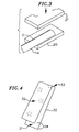
- each hose Prior to being spliced, each hose is preferably preheated, as shown for hose 1a in FIG. 3.
- Preheating serves several purposes. First, preheating increases the pliability of the plastic film that makes up each hose. Second, preheating facilitates bonding by decreasing the difference in the ambient temperature of the plastic film versus the melting point of the splicing insert that is bonded internally to each hose (described below). Preheating normalizes the hoses' ambient temperatures and the subsequent application of heat by a heating means (also described below) is directed solely to forming a perfect bond between the hoses and the splicing insert.
- preheating is required to crease the offsets formed in each of the hoses when thicker mils, such as 0,38 mm (15 mil), are used (described below as a further embodiment).
- preheating is not required for all mil thicknesses and ambient temperatures, it is useful to perform preheating nevertheless for the sake of consistency in performing the splicing process.
- hose 1a is placed on a lower heating element 20 with track 2 facing upwards.
- An upper stamp 21, preferably covered and padded, is moved downwardly to compress hose 1 which should remain in a compressed and heated state for approximately 3 seconds. The preheating is repeated for hose 1b.
- Splicing means for splicing together a pair of hoses 1a and 1b is shown in FIG. 4.
- a splicing insert 30 is sized to fit internal to the hoses affixed to an inside surface of each hose on a wall opposite track 2.
- splicing insert 30 has a bonding surface 31 made up of co-polymer polyethylene and an opposite non-bonding surface 32 made up of polyester.
- bonding surface 31 fuses to lower inside surface 7b of hoses 1a and 1b while non-bonding surface 32 does not fuse.
- This allows hoses 1a and 1b to be spliced with splicing means internal to the hoses that does not constrict supply tube 3. Water therefore flows unimpeded through the splice.
- Other materials having similar bonding characteristics could be used in addition to polyester/co-polymer polyethylene insert 30.
- splicing insert 30 is substantially equal in width to the transverse inner dimension of the hoses.
- Splicing insert 30 must be at least as long as the primary seal and, if a pair of secondary seals are used, as long as the primary seal and secondary seals combined. In a preferred embodiment, each seal 9,52 mm is (3/8") long.
- the primary seal and secondary seals are described below.
- the splicing insert 30 should be long enough so that there is a slight gap between the primary seal and each of the secondary seals with a slight extension on both outside ends of the secondary seals. The gaps and extensions are preferable so that the hoses do not seal themselves off during the steps of forming the secondary seals.
- the splicing insert 30 preferably folded to form transverse crease 33 and slight offset 34 from center with the bonding surface 31 on the inside.
- the offset 34 is formed along the transverse ends of the splicing insert 30, preferably offset by about (3/16") 4,76 mm.
- the splicing insert 30 is next unfolded and inserted into hose 1a with the bonding surface 31 facing downwards towards an inside hose surface on a wall opposite track 2. Additionally, the end of the splicing insert 30 defining offset 34 is inserted into hose 1a until transverse crease 33 is aligned with the end of hose 1a, as shown in FIG. 5. The transverse crease 33 serves as a measuring guide and ensures that the splicing insert 30 is properly centered when the other hose is positioned over it.
- the pair of hoses 1a and 1b are connected by inserting the other half of the splicing insert 30 into hose 1b, as shown in FIG. 6.
- the pair of hoses 1a and 1b must be aligned along the longitudinal axis 11 of hoses 1a and 1b and positioned to form an overlapping junction 40. It is critical that the pair of hoses be in axial alignment to ensure an optimal splice and that no creases are formed in the hose material at any point around the junction 40.
- the junction 40 forms an overlap 41 of substantially 4,76 mm (3/16"), that is, overlap 41 is equal in length to offset 34 so that equal lengths of insert 30 contact both hoses 1a and 1b.
- junction 40 could also be formed by butting together the ends of the pair of hoses or by adding material to bridge a gap formed between the respective hose ends. It is essential that a uniform overlap 41 be formed throughout the junction 40 of hoses 1a and 1b.
- junction 40 is manually pressed flat without heating and the connected hoses are allowed to rebound to their original ovoidal shapes.
- the overlap 41 is then checked for circumferential uniformity.
- Insert 30 is next fused to lower inside surface 7b of connected hoses 1a and 1b by heating the connected hoses between lower heating element 20 and upper stamp 21, as shown in FIG. 7.
- the connected hoses are placed on the lower heating element 20 with track 2 facing upwards.
- the upper stamp 21 is moved downwardly to compress the connected hoses which remains in a compressed and heated state long enough for insert 30 to properly bond to both hoses 1a and 1b.
- the amount of time needed varies according to the mil thickness and ambient temperatures, but is typically between 5 to 15 seconds.
- the combination of heat and pressure cause insert 30 to bond the inside surfaces of hoses 1a and 1b into a unitary structure with insert 30.
- the splicing insert 30 becomes permanently affixed to each hose 1.
- thermal impulse heat sealing is a process of welding thermal plastic films in which the films are clamped by a pair of jaws, heated to their welding temperature by a short powerful impulse and cooled while still under pressure.
- a typical thermal impulse heat sealer comprises a pair of jaws forming fusing surfaces, one of which is a resilient pressure jaw and the other a heater jaw containing a heating element in the form of a metal strip of very low heat capacity.
- an electrical impulse is applied to the heater jaw for a short period, generally less than a second, instantaneously heating the plastic films making up the hoses to their welding temperature. After a short time sufficient to allow the weld to cool under pressure and for the splice to develop satisfactory strength, the jaws are opened and the welded hoses removed.
- the overlapping junction 40 is fused circumferentially to create primary seal 50 by melting the pair of hose ends together.
- the junction 40 is placed on a lower fusing surface 52 with track 2 facing downwards and centered on junction 40, as shown in FIG. 9A so that the first half of a primary seal is formed on the track side of the junction 40.
- the hoses 1a and 1b are placed in horseshoe guides 53a and 53b.
- An upper resilient pressure element (not shown) is moved downwardly to compress hose 1.
- the compressed hoses are heated for approximately 3 seconds and remain in a compressed state for an additional 17 seconds.
- the entire thermal impulse heat sealing procedure takes approximately 20 seconds.
- the connected hoses are turned over and the fusing step is repeated, as shown in FIG. 9B so that the second half of a primary seal is formed on the underside of the junction 40.
- a pair of secondary seals 51a and 51b parallel to either side of the primary seal 50 on an underside surface of hoses 1a and 1b near the ends of splicing insert 30 are formed, as also shown in FIG. 8.
- the secondary seals 51a and 51b only seal the splicing insert 30 to lower inside surface 7b of hoses 1a and 1b and do not affect the other inside surfaces.
- the purpose of the secondary seals 51a and 51b is to ensure that the splicing insert 30 remains permanently affixed to the inside surface of each hose 1 and is generally only required for heavier plastic films of approximately 10 mil to 15 mil in thickness.
- the secondary seals 51a and 51b are precautionary measures for thicker mil plastic films to ensure that the splicing insert 30 stays sealed by further fusing the ends of the splicing insert 30 to hoses 1a and 1b.
- a similar procedure for forming the primary seal 50 is used for forming secondary seals 51a and 51b.
- hose 1b is placed on the lower fusing surface 52 parallel to the primary seal with track 2 facing upwards and the lower fusing surface 52 located near the end of splicing insert 30, as shown in FIG. 9C.
- the hoses 1a and 1b are placed in horseshoe guides 53a and 53b.
- An upper resilient pressure element (not shown) is moved downwardly to compress hose 1b. The compressed hoses are heated for approximately 3 seconds and remain in a compressed state for an additional 17 seconds.
- hose 1a is placed on the lower fusing surface 52 parallel to the primary seal with track 2 facing upwards and the lower fusing surface 52 near the other end of splicing insert 30, as shown in FIG. 9D.
- An upper resilient pressure element (not shown) is moved downwardly to compress hose 1a.
- the compressed hoses are heated for approximately 3 seconds and remain in a compressed state for an additional 17 seconds.
- the hoses 1a and 1b are placed in horseshoe guides 53a and 53b.
- the track 2 of hoses 1a and 1b is offset, as shown in FIGS. 10A and 10B and 11.
- Offsetting simply means that the hose is refolded so that the track 2 no longer runs longitudinally but is skewed either to the left (FIG. 10A) or the right (FIG. 10B) such that the respective tracks do not overlap when the pair of hoses 1a and 1b are connected together.
- the purpose of offsetting each hose is to lower the energy and heat required to fuse the junction 40 by minimizing the number of layers of overlapping plastic film.
- the offsetting of each track 2 causes the spliced hoses to define a discontinuous track, as shown in FIG. 12.
- each hose is offset by shifting the track to either the left or right and refolding the edges of the hose, preferably extending approximately 45,72 cm (18") away from the cut end.
- the respective offsets of hoses 1a and 1b are shown in the side view depicted in FIG. 11.
- each of the connected hoses 1 are again refolded at their edges, preferably extending about 36,58 cm (12") away from the primary seal 50.
- each track 2 continues in its longitudinal orientation outward from the offset in a normal condition beginning about 30,48 cm (12") from either side of the primary seal 50.
- the further embodiment is particularly of use with plastic films of 0,38 mm (15 mil) thickness.
Landscapes
- Engineering & Computer Science (AREA)
- Mechanical Engineering (AREA)
- Life Sciences & Earth Sciences (AREA)
- Soil Sciences (AREA)
- Water Supply & Treatment (AREA)
- Environmental Sciences (AREA)
- Physics & Mathematics (AREA)
- Thermal Sciences (AREA)
- Lining Or Joining Of Plastics Or The Like (AREA)
- Quick-Acting Or Multi-Walled Pipe Joints (AREA)
- Rigid Pipes And Flexible Pipes (AREA)
Claims (10)
- Ein Verfahren zum Spleißen eines Paars von Tropfbewässerungsschläuchen unter Verwendung von Verbindungsmitteln innerhalb des Schlauchespaars, das folgende Schritte umfasst:Verbinden des Schlauchpaars in axialer Fluchtung, um eine Verbindungsstelle mit dem Verbindungsmittel zu formen, das innerhalb jedes Schlauchs eingeschoben ist;Kleben des Verbindungsmittels an einen ersten Umfangsabschnitt einer Innenfläche jedes Schlauches, um das Schlauchpaar und das Verbindungsmitteln zu einer unitären Einheit zu gestalten; undFormen einer Dichtung unter Verwendung von Mitteln zur Umfangsabdichtung an der Verbindungsstelle, um eine wasserdichte Dichtung zu schaffen, wobei das Spleißmittel einen zweiten Umfangsabschnitt der Innenflächen der Schläuche, die dem Spleißmittel gegenüberliegen, darin hindert sich während der Dichtungsbildung an besagtes Spleißmittel zu kleben.
- Ein Verfahren nach Anspruch 1 wobei der Schritt des Klebens weiter folgende Schritte umfasst:Zusammenpressen des Schlauchpaars, unter Verwendung der Verschmelzmittel um die Verbindungsstelle; undVerschmelzen des Spleißmittels mit jedem Schlauch unter Verwendung eines Verschmelzmittels, um zu bewirken, dass sich das Verbindungsmittel mit der Innenfläche jedes Schlauchs verklebt.
- Ein Verfahren nach Anspruch 1 wobei der Schritt zum Formen einer Dichtung weiter folgende Schritte einschließt:Verschmelzen einer unteren Hälfte der Verbindungsstelle unter Verwendung des Dichtungsmittels; undVerschmelzen einer oberen Hälfte der Verbindungsstelle unter Verwendung des Dichtungsmittels.
- Ein Verfahren zum Spleißen eines Paars von Tropfbewässerungsschläuchen, das folgende Schritte umfasstEinschieben eines ersten Endes eines Spleißeinsatzes in ein Ende eines faltbaren ersten zu spleißenden Schlauches;Einschieben eines zweiten Endes des Spleißeinsatzes in ein Ende eines faltbaren zweiten zu spleißenden Schlauches;Kleben des Einsatzes an eine Innenfläche jedes Schlauches;Zusammendrücken der Schlauchenden über dem verklebten Einsatz durch Aufbringen von Druck über die Schlauchenden; undErwärmen der zusammengedrückten Schlauchenden, um die Schlauchenden zu verschmelzen und eine Spleißung zu schaffen.
- Ein Verfahren nach Anspruch 4 wobei der Spleißeinsatz verhindert, dass sich die Schläuche im zusammengefallenen Zustand zukleben.
- Ein Verfahren nach Anspruch 4 wobei der Spleißeinsatz nur eine aktivierbare Klebefläche aufweist und wobei der Klebeschritt weiter den Schritt der Aktivierung der Klebefläche zum Kleben des Spleißeinsatzes an die Innenfläche jedes Schlauches umfasst.
- Ein Verfahren nach Anspruch 7, das weiter den Schritt der Zentrierung des Einsatzes zwischen den ersten und zweiten Schläuchen umfasst.
- Ein Verfahren nach Anspruch 7 wobei der Spleißeinsatz eine Klebefläche aufweist und wobei der Zentrierschritt folgende Schritte umfasst:Falten des Einsatzes auf sich selbst, was eine Falte formt, die den Einsatz in einen ersten unteren Abschnitt und einen zweiten oberen Abschnitt teilt wobei sich der erste Abschnitt um eine vorbestimmte Distanz über den zweiten Abschnitt hinaus erstreckt und einen Absatz bildet;Entfalten des Einsatzes;Einschieben des ersten Abschnitts des Einsatzes in das Ende des ersten Schlauches, Fluchten der Falte mit dem Ende des ersten Schlauches und Positionieren der Klebefläche des ersten Abschnitts des gefalteten Einsatzes , um Kontakt mit einer unteren Fläche des ersten Schlauches zu machen;Einschieben des zweiten Abschnitts des Einsatzes in das Ende des zweiten Schlauches; undSchieben des Endes des zweiten Schlauches über das Ende des ersten Schlauches und Überlappen des Endes des ersten Schlauches um eine Distanz, die etwa der vorbestimmten Distanz des Absatzes gleicht.
- Ein Verfahren nach Anspruch 4 wobei das Paar von Schläuchen eine Tropfspur longitudinal entlang einer ersten Wand jedes Schlauches aufweist und wobei der Klebeschritt das Kleben des Einsatzes an eine Innenfläche einer Wand umfasst, die der ersten Wand gegenüberliegt.
- Ein Verfahren nach Anspruch 4 wobei jeder Schlauch Auslässe entlang seiner Tropfspur aufweist, das Verfahren weiter den Schritt des Schneidens jedes Schlauch senkrecht zu seiner Längsachse an einer Stelle umfasst, die in der Mitte zwischen Auslässen liegt, welche das zu verbindende Schlauchende formen.
Applications Claiming Priority (3)
| Application Number | Priority Date | Filing Date | Title |
|---|---|---|---|
| US517600 | 1983-07-26 | ||
| US08/517,600 US5690769A (en) | 1995-08-21 | 1995-08-21 | Method for splicing drip irrigation hoses using splicing means internal to the hoses |
| PCT/US1996/013525 WO1997006954A1 (en) | 1995-08-21 | 1996-08-21 | Method for splicing drip irrigation hoses using splicing means internal to the hoses |
Publications (3)
| Publication Number | Publication Date |
|---|---|
| EP0846059A1 EP0846059A1 (de) | 1998-06-10 |
| EP0846059A4 EP0846059A4 (de) | 2001-04-11 |
| EP0846059B1 true EP0846059B1 (de) | 2004-03-17 |
Family
ID=24060459
Family Applications (1)
| Application Number | Title | Priority Date | Filing Date |
|---|---|---|---|
| EP96928968A Expired - Lifetime EP0846059B1 (de) | 1995-08-21 | 1996-08-21 | Verfahren zum spleissen von tropfbewässerungsschläuchen unter verwendung von verbindungsmitteln innerhalb des schlauches |
Country Status (10)
| Country | Link |
|---|---|
| US (2) | US5690769A (de) |
| EP (1) | EP0846059B1 (de) |
| AT (1) | ATE261816T1 (de) |
| AU (1) | AU6853896A (de) |
| DE (1) | DE69631887T2 (de) |
| ES (1) | ES2213778T3 (de) |
| IL (1) | IL123446A (de) |
| PT (1) | PT846059E (de) |
| WO (1) | WO1997006954A1 (de) |
| ZA (1) | ZA967103B (de) |
Families Citing this family (15)
| Publication number | Priority date | Publication date | Assignee | Title |
|---|---|---|---|---|
| GB9719104D0 (en) | 1997-09-10 | 1997-11-12 | Supreme Plastics Group Ltd | Splicing unit and method of splicing |
| US6183584B1 (en) * | 1998-04-03 | 2001-02-06 | T-Systems International, Inc. | Method for splicing drip irrigation hoses using two member splicing coupling |
| US6090233A (en) * | 1998-05-01 | 2000-07-18 | Drip Tape Manufacturers & Engineers, Inc. | Irrigation hose splice and method of making same |
| US6368440B1 (en) * | 2000-03-22 | 2002-04-09 | Xerox Corporation | Method for fabricating a flexible belt with a puzzle-cut seam |
| US6632306B1 (en) | 2000-08-07 | 2003-10-14 | Roberts Group Holdings, Llc | Method and apparatus for splicing drip irrigation tape |
| USD450550S1 (en) | 2000-11-16 | 2001-11-20 | Roberts Group Holdings, Llc | Flow channel for drip irrigation with biased cavity |
| USD455055S1 (en) | 2000-11-16 | 2002-04-02 | Roberts Groups Holdings, Llc | Flow channel for drip irrigation with central cavity |
| US6540859B1 (en) | 2001-10-16 | 2003-04-01 | The Toro Company | Method for splicing hose |
| JP3965329B2 (ja) * | 2002-06-20 | 2007-08-29 | 東洋鋼鈑株式会社 | 樹脂フィルムの接続方法および接続装置 |
| WO2004102057A2 (en) * | 2003-05-13 | 2004-11-25 | Federal-Mogul Powertrain, Inc. | Sleeve splicing kit and method |
| US20090051159A1 (en) * | 2007-08-20 | 2009-02-26 | Scott Glenn Cameron | Fluid fitting for an agricultural drip irrigation system |
| USD781115S1 (en) * | 2014-08-29 | 2017-03-14 | Rivulis Irrigation Ltd. | Dripper |
| DE102017106906A1 (de) * | 2017-03-30 | 2018-10-04 | Tpu Plus Gmbh | Verfahren zum Verschweißen |
| CN116100630B (zh) * | 2023-02-07 | 2023-09-12 | 山东春雨节水灌溉设备有限公司 | 一种外镶管件输水带的加工设备及加工工艺 |
| CN116210566B (zh) * | 2023-03-15 | 2024-10-11 | 山东长江节水灌溉科技有限公司 | 具有层压复合紊流道的补偿式地埋渗灌管带及其加工方法 |
Family Cites Families (16)
| Publication number | Priority date | Publication date | Assignee | Title |
|---|---|---|---|---|
| US3635504A (en) * | 1968-10-07 | 1972-01-18 | Goodall Rubber Co | Hose splice |
| US3666586A (en) * | 1970-11-10 | 1972-05-30 | Edward H Lacey | Cord reinforced hose splicing method |
| NL157234B (nl) * | 1973-11-27 | 1978-07-17 | Wavin Bv | Werkwijze en inrichting voor het aan elkaar lassen van twee polyalkeenkunststofvoorwerpen, alsmede aan elkaar gelaste voorwerpen verkregen volgens deze werkwijze. |
| US4092193A (en) * | 1975-06-30 | 1978-05-30 | Raychem Corporation | Method for joining substrates utilizing coupling means |
| FR2322732A1 (fr) * | 1975-09-05 | 1977-04-01 | Viscora Sa | Procede d'aboutage de troncons tubulaires pour former des enveloppes tubulaires a communication longitudinale continue, et articles obtenus par ce procede |
| US4204897A (en) * | 1978-07-25 | 1980-05-27 | The Goodyear Tire & Rubber Company | Method and apparatus for splicing hose |
| US4215516A (en) * | 1979-04-18 | 1980-08-05 | Sheldahl, Inc. | Unidirectional tape |
| US4247051A (en) * | 1979-12-20 | 1981-01-27 | Davies Allport | Irrigation hose and method for its construction |
| SE436255B (sv) * | 1983-01-04 | 1984-11-26 | Fiab System Ab | Forfarande for skarvning av foretredesvis rorformiga kroppar ende mot ende samt en anordning for genomforande av forfarandet |
| US4630846A (en) * | 1983-04-07 | 1986-12-23 | Hitachi Zosen Corporation | Pipe joint |
| US4610742A (en) * | 1984-11-15 | 1986-09-09 | Teepak, Inc. | Methods and materials for splicing tubular food casings |
| DE3636891A1 (de) * | 1986-10-30 | 1988-05-11 | Armin Dommer | Verfahren und vorrichtung zum stumpfschweissen von kunststoff-rohrabschnitten oder kunststoff-formstuecken |
| US4736775A (en) * | 1986-12-24 | 1988-04-12 | Viskase Corporation | Food casing splice having dual pressure sensitive tapes |
| US4906313A (en) * | 1988-05-09 | 1990-03-06 | R. W. Lyall & Company, Inc. | Fusion weld method and assembly for forming a fusion welded joint between pipe sections |
| FR2654978B1 (fr) * | 1989-11-29 | 1992-02-21 | Gaz De France | Piece de raccordement du type a resistance electrique perfectionnee pour la reunion par thermosoudage d'elements en matiere plastique. |
| US5175032A (en) * | 1991-05-02 | 1992-12-29 | Shaw Industries Ltd. | Heat shrinkable closure sheets and sleeve structures and methods employing the same |
-
1995
- 1995-08-21 US US08/517,600 patent/US5690769A/en not_active Ceased
-
1996
- 1996-08-21 IL IL12344696A patent/IL123446A/xx not_active IP Right Cessation
- 1996-08-21 EP EP96928968A patent/EP0846059B1/de not_active Expired - Lifetime
- 1996-08-21 DE DE69631887T patent/DE69631887T2/de not_active Expired - Lifetime
- 1996-08-21 ES ES96928968T patent/ES2213778T3/es not_active Expired - Lifetime
- 1996-08-21 AU AU68538/96A patent/AU6853896A/en not_active Abandoned
- 1996-08-21 PT PT96928968T patent/PT846059E/pt unknown
- 1996-08-21 WO PCT/US1996/013525 patent/WO1997006954A1/en not_active Ceased
- 1996-08-21 AT AT96928968T patent/ATE261816T1/de not_active IP Right Cessation
- 1996-08-21 ZA ZA9607103A patent/ZA967103B/xx unknown
-
1999
- 1999-10-25 US US09/426,467 patent/USRE37097E1/en not_active Expired - Lifetime
Also Published As
| Publication number | Publication date |
|---|---|
| EP0846059A4 (de) | 2001-04-11 |
| PT846059E (pt) | 2004-05-31 |
| ATE261816T1 (de) | 2004-04-15 |
| US5690769A (en) | 1997-11-25 |
| USRE37097E1 (en) | 2001-03-20 |
| ZA967103B (en) | 1998-02-23 |
| AU6853896A (en) | 1997-03-12 |
| DE69631887D1 (de) | 2004-04-22 |
| WO1997006954A1 (en) | 1997-02-27 |
| IL123446A0 (en) | 1998-10-30 |
| DE69631887T2 (de) | 2005-03-03 |
| ES2213778T3 (es) | 2004-09-01 |
| EP0846059A1 (de) | 1998-06-10 |
| IL123446A (en) | 2000-10-31 |
Similar Documents
| Publication | Publication Date | Title |
|---|---|---|
| US5690769A (en) | Method for splicing drip irrigation hoses using splicing means internal to the hoses | |
| US4365144A (en) | Apparatus for welding a joint between plastic pipes | |
| US3788928A (en) | Method of forming a lap joint between tubular articles of thermoplastic material | |
| CA1193641A (en) | Bifilar resistance element, heating element made therefrom, and process for preparing heating element made therefrom | |
| KR102444335B1 (ko) | 폴리에틸렌 파이프라인의 전기융합을 위한 장치 및 시스템 | |
| AU2002330343B9 (en) | Method for sealing a plastic spout | |
| JPH0557480B2 (de) | ||
| CN112912316B (zh) | 方底包装袋、包装体、及方底包装袋的制造方法 | |
| BR0108576B1 (pt) | saco plástico "camiseta t" e método de fabricação de um saco plástico. | |
| US4851647A (en) | Process for welding butt-jointed plastic tubes and welding device for performing the process | |
| DE69709713D1 (de) | Verfahren und vorrichtung zum zusammenfügen, reparieren und wartung von mit einer isolierschicht versehenen rohren | |
| KR101635426B1 (ko) | 이중보온관 연결용 케이싱을 이용한 이중보온관 연결방법 | |
| FI70849B (fi) | Foerfarande och organ foer anslutning och taetning av materialdelar och anvaendning av ifraogavarande organ i behaollare | |
| EP1051328B1 (de) | Verfahren und vorrichtung zum verschliessen des endes von verpackungstuben | |
| JPS61266227A (ja) | パウチ溶接用チユ−ブインサ−ト | |
| JPH0694167B2 (ja) | 2個のフォイル間にそう入体を溶着する方法 | |
| CN100548818C (zh) | 用于逆密封包装容器的方法及设备 | |
| US6183584B1 (en) | Method for splicing drip irrigation hoses using two member splicing coupling | |
| EP0396713B1 (de) | Versiegelung von kabelverbindungsverschlüssen | |
| JP3093002B2 (ja) | 管継手の製造方法 | |
| JPH09324888A (ja) | 補修用電気融着プラグ | |
| WO2004008016A1 (en) | Method for joining and/or sealing thermoplastic pipes | |
| JPS6134375B2 (de) | ||
| JPH04201861A (ja) | ジッパー爪付袋及びその製法 | |
| JPH0377771B2 (de) |
Legal Events
| Date | Code | Title | Description |
|---|---|---|---|
| PUAI | Public reference made under article 153(3) epc to a published international application that has entered the european phase |
Free format text: ORIGINAL CODE: 0009012 |
|
| 17P | Request for examination filed |
Effective date: 19980223 |
|
| AK | Designated contracting states |
Kind code of ref document: A1 Designated state(s): AT BE DE ES FR GB GR IE IT PT |
|
| A4 | Supplementary search report drawn up and despatched |
Effective date: 20010222 |
|
| AK | Designated contracting states |
Kind code of ref document: A4 Designated state(s): AT BE DE ES FR GB GR IE IT PT |
|
| RIC1 | Information provided on ipc code assigned before grant |
Free format text: 7B 32B 31/00 A, 7A 01G 25/02 B, 7B 29C 65/00 B |
|
| GRAP | Despatch of communication of intention to grant a patent |
Free format text: ORIGINAL CODE: EPIDOSNIGR1 |
|
| GRAS | Grant fee paid |
Free format text: ORIGINAL CODE: EPIDOSNIGR3 |
|
| GRAA | (expected) grant |
Free format text: ORIGINAL CODE: 0009210 |
|
| AK | Designated contracting states |
Kind code of ref document: B1 Designated state(s): AT BE DE ES FR GB GR IE IT PT |
|
| REG | Reference to a national code |
Ref country code: GB Ref legal event code: FG4D |
|
| REG | Reference to a national code |
Ref country code: IE Ref legal event code: FG4D |
|
| REF | Corresponds to: |
Ref document number: 69631887 Country of ref document: DE Date of ref document: 20040422 Kind code of ref document: P |
|
| REG | Reference to a national code |
Ref country code: PT Ref legal event code: SC4A Free format text: AVAILABILITY OF NATIONAL TRANSLATION Effective date: 20040406 |
|
| REG | Reference to a national code |
Ref country code: GR Ref legal event code: EP Ref document number: 20040401797 Country of ref document: GR |
|
| REG | Reference to a national code |
Ref country code: ES Ref legal event code: FG2A Ref document number: 2213778 Country of ref document: ES Kind code of ref document: T3 |
|
| ET | Fr: translation filed | ||
| PLBE | No opposition filed within time limit |
Free format text: ORIGINAL CODE: 0009261 |
|
| STAA | Information on the status of an ep patent application or granted ep patent |
Free format text: STATUS: NO OPPOSITION FILED WITHIN TIME LIMIT |
|
| 26N | No opposition filed |
Effective date: 20041220 |
|
| PGFP | Annual fee paid to national office [announced via postgrant information from national office to epo] |
Ref country code: IE Payment date: 20090825 Year of fee payment: 14 Ref country code: FR Payment date: 20090817 Year of fee payment: 14 Ref country code: ES Payment date: 20090826 Year of fee payment: 14 |
|
| PGFP | Annual fee paid to national office [announced via postgrant information from national office to epo] |
Ref country code: PT Payment date: 20090805 Year of fee payment: 14 Ref country code: GB Payment date: 20090825 Year of fee payment: 14 Ref country code: AT Payment date: 20090803 Year of fee payment: 14 |
|
| PGFP | Annual fee paid to national office [announced via postgrant information from national office to epo] |
Ref country code: DE Payment date: 20090827 Year of fee payment: 14 |
|
| PGFP | Annual fee paid to national office [announced via postgrant information from national office to epo] |
Ref country code: BE Payment date: 20090915 Year of fee payment: 14 |
|
| PGFP | Annual fee paid to national office [announced via postgrant information from national office to epo] |
Ref country code: IT Payment date: 20090827 Year of fee payment: 14 |
|
| PGFP | Annual fee paid to national office [announced via postgrant information from national office to epo] |
Ref country code: GR Payment date: 20090827 Year of fee payment: 14 |
|
| BERE | Be: lapsed |
Owner name: *T-SYSTEMS INTERNATIONAL INC. Effective date: 20100831 |
|
| REG | Reference to a national code |
Ref country code: PT Ref legal event code: MM4A Free format text: LAPSE DUE TO NON-PAYMENT OF FEES Effective date: 20110221 |
|
| GBPC | Gb: european patent ceased through non-payment of renewal fee |
Effective date: 20100821 |
|
| REG | Reference to a national code |
Ref country code: FR Ref legal event code: ST Effective date: 20110502 |
|
| REG | Reference to a national code |
Ref country code: IE Ref legal event code: MM4A |
|
| PG25 | Lapsed in a contracting state [announced via postgrant information from national office to epo] |
Ref country code: IT Free format text: LAPSE BECAUSE OF NON-PAYMENT OF DUE FEES Effective date: 20100821 Ref country code: AT Free format text: LAPSE BECAUSE OF NON-PAYMENT OF DUE FEES Effective date: 20100821 Ref country code: PT Free format text: LAPSE BECAUSE OF NON-PAYMENT OF DUE FEES Effective date: 20110221 |
|
| REG | Reference to a national code |
Ref country code: DE Ref legal event code: R119 Ref document number: 69631887 Country of ref document: DE Effective date: 20110301 |
|
| PG25 | Lapsed in a contracting state [announced via postgrant information from national office to epo] |
Ref country code: GR Free format text: LAPSE BECAUSE OF NON-PAYMENT OF DUE FEES Effective date: 20110302 |
|
| PG25 | Lapsed in a contracting state [announced via postgrant information from national office to epo] |
Ref country code: IE Free format text: LAPSE BECAUSE OF NON-PAYMENT OF DUE FEES Effective date: 20100823 Ref country code: BE Free format text: LAPSE BECAUSE OF NON-PAYMENT OF DUE FEES Effective date: 20100831 Ref country code: FR Free format text: LAPSE BECAUSE OF NON-PAYMENT OF DUE FEES Effective date: 20100831 Ref country code: DE Free format text: LAPSE BECAUSE OF NON-PAYMENT OF DUE FEES Effective date: 20110301 |
|
| PG25 | Lapsed in a contracting state [announced via postgrant information from national office to epo] |
Ref country code: GB Free format text: LAPSE BECAUSE OF NON-PAYMENT OF DUE FEES Effective date: 20100821 |
|
| REG | Reference to a national code |
Ref country code: ES Ref legal event code: FD2A Effective date: 20111019 |
|
| PG25 | Lapsed in a contracting state [announced via postgrant information from national office to epo] |
Ref country code: ES Free format text: LAPSE BECAUSE OF NON-PAYMENT OF DUE FEES Effective date: 20100822 |