EP0844902B2 - Fixation rapide pour planche a neige - Google Patents
Fixation rapide pour planche a neige Download PDFInfo
- Publication number
- EP0844902B2 EP0844902B2 EP97932491A EP97932491A EP0844902B2 EP 0844902 B2 EP0844902 B2 EP 0844902B2 EP 97932491 A EP97932491 A EP 97932491A EP 97932491 A EP97932491 A EP 97932491A EP 0844902 B2 EP0844902 B2 EP 0844902B2
- Authority
- EP
- European Patent Office
- Prior art keywords
- binding
- locking member
- snowboard
- boot
- configuration
- Prior art date
- Legal status (The legal status is an assumption and is not a legal conclusion. Google has not performed a legal analysis and makes no representation as to the accuracy of the status listed.)
- Expired - Lifetime
Links
Images


Classifications
-
- A—HUMAN NECESSITIES
- A63—SPORTS; GAMES; AMUSEMENTS
- A63C—SKATES; SKIS; ROLLER SKATES; DESIGN OR LAYOUT OF COURTS, RINKS OR THE LIKE
- A63C10/00—Snowboard bindings
- A63C10/02—Snowboard bindings characterised by details of the shoe holders
- A63C10/10—Snowboard bindings characterised by details of the shoe holders using parts which are fixed on the shoe, e.g. means to facilitate step-in
- A63C10/103—Snowboard bindings characterised by details of the shoe holders using parts which are fixed on the shoe, e.g. means to facilitate step-in on the sides of the shoe
-
- A—HUMAN NECESSITIES
- A43—FOOTWEAR
- A43B—CHARACTERISTIC FEATURES OF FOOTWEAR; PARTS OF FOOTWEAR
- A43B5/00—Footwear for sporting purposes
- A43B5/04—Ski or like boots
- A43B5/0401—Snowboard boots
-
- A—HUMAN NECESSITIES
- A43—FOOTWEAR
- A43B—CHARACTERISTIC FEATURES OF FOOTWEAR; PARTS OF FOOTWEAR
- A43B5/00—Footwear for sporting purposes
- A43B5/04—Ski or like boots
- A43B5/0401—Snowboard boots
- A43B5/0403—Adaptations for soles or accessories with soles for snowboard bindings
-
- A—HUMAN NECESSITIES
- A43—FOOTWEAR
- A43B—CHARACTERISTIC FEATURES OF FOOTWEAR; PARTS OF FOOTWEAR
- A43B5/00—Footwear for sporting purposes
- A43B5/04—Ski or like boots
- A43B5/0415—Accessories
- A43B5/0417—Accessories for soles or associated with soles of ski boots; for ski bindings
- A43B5/0423—Accessories for soles or associated with soles of ski boots; for ski bindings located on the sides of the sole
-
- A—HUMAN NECESSITIES
- A63—SPORTS; GAMES; AMUSEMENTS
- A63C—SKATES; SKIS; ROLLER SKATES; DESIGN OR LAYOUT OF COURTS, RINKS OR THE LIKE
- A63C10/00—Snowboard bindings
- A63C10/02—Snowboard bindings characterised by details of the shoe holders
- A63C10/10—Snowboard bindings characterised by details of the shoe holders using parts which are fixed on the shoe, e.g. means to facilitate step-in
-
- A—HUMAN NECESSITIES
- A63—SPORTS; GAMES; AMUSEMENTS
- A63C—SKATES; SKIS; ROLLER SKATES; DESIGN OR LAYOUT OF COURTS, RINKS OR THE LIKE
- A63C10/00—Snowboard bindings
- A63C10/16—Systems for adjusting the direction or position of the bindings
- A63C10/18—Systems for adjusting the direction or position of the bindings about a vertical rotation axis relative to the board
Definitions
- the present invention relates to a snowboard binding for interfacing a boot to a snowboard.
- binding systems for soft snowboard boots suffer from a disadvantage in that they are not "step-in" systems that can be automatically actuated by the rider simply stepping into the binding.
- These bindings typically include a rigid high back piece into which the heel of the boot is placed, and one or more straps that secure the boot to the binding.
- Such bindings can be somewhat inconvenient to use because after each run, the rider must unbuckle each strap to release the boot when getting on the chair lift, and he must re-buckle each strap before the next run.
- a further disadvantage of conventional bindings that employ rigid engagement members and an actuation handle or lever is that they generally employ a large spring that biases the binding to hold it in the closed position. Thus, to open the binding, the rider must exert substantial force on the handle or lever, making the binding difficult to use.
- a snowboard binding for securing a boot to a snowboard.
- the binding comprises a base, a first engagement member that is supported by the base and adapted to engage a first lateral side of the boot, and a second engagement member, pivotally mounted to the base, that is adapted to engage a second lateral side of the boot opposite the first lateral side of the boot.
- the snowboard binding is provided with a trigger that is adapted to receive the bottom of the snowboard boot and, when moved via contact with boot, to cause the pivotal engagement member to pivot into engagement with the snowboard boot.
- the present invention is directed to an apparatus for engaging a snowboard boot to a snowboard.
- a binding is provided that is automatically closed when a rider steps into the binding. Furthermore, the binding advantageously provides substantial locking force while requiring a small opening force.
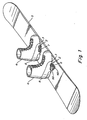
- Fig. 1 is a perspective view of a pair of snowboard boots 4 mounted to a snowboard 5 via a pair of bindings 2 in accordance with one illustrative embodiment of the present invention.
- the bindings each may include a hold down disc, discussed below, that enables the angle of the rider's feet relative to the longitudinal axis of the snowboard to be adjusted to a position that the rider finds most comfortable.
- the bindings 2 each includes a pair of engagement members for engaging the lateral sides of the boots, and a handle 40.
- the binding is constructed and arranged so that the engagement members automatically lock the boot 4 in the binding when the rider steps into the binding, without requiring actuation of the handle 40.
- the handle 40 is used only to move the binding from a locked position to an unlocked position, and can do so without substantial force from the rider.
- the binding of the present invention enables quick and easy engagement and disengagement of the rider's boots with the board.
- the rider simply steps into the bindings 2, which causes the engagement members to automatically secure the boots 4 to the board 5.
- the rider can lift the handle 40 of the rear binding to disengage the binding and free the rear boot, thereby enabling the rider to use the rear leg to push the snowboard along the chair lift.
- the binding 40 automatically assumes the open position wherein it is prepared to receive and automatically engage the boot.
- the rider can simply step into the binding to automatically lock the boot in place, and begin the next run.
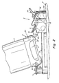
- the binding 2 includes a housing that includes a base plate 3 that is mounted to the snowboard and a cover 50 that covers the binding locking mechanism.
- the binding further includes a pair of engagement members 6 and 7 that are mounted to the housing.
- engagement member 7 is fixed to baseplate 3 and engagement member 6 is movable, and in particular pivotable, with respect thereto.
- the binding is adapted to engage a snowboard boot 4 having lateral recesses 54 on either side for receiving the engagement members 6 and 7.
- the lateral recesses 54 may be provided in the boot via an interface 8 (as described in DE 196 16 559 A1 which was published after the filing date of the present publication and to which the skilled reader is referred for details) which is a single-piece molded plastic part bonded to the sole of the boot.
- an interface 8 as described in DE 196 16 559 A1 which was published after the filing date of the present publication and to which the skilled reader is referred for details
- the invention is not limited in this respect, and that the binding of the present invention can be used with boots that are adapted in other ways to engage the binding.
- the rider steps into the binding by first aligning the fixed engagement member 7 with the recess 54 on the inside of the boot.
- the engagement member 7 is arranged in a substantially horizontal configuration that extends substantially parallel to the baseplate 3 and the snowboard.
- the boot 4 is angled slightly when bringing the recess 54 into contact with the engagement member 7.
- the upper surface 60 of the recess is angled upwardly from the back of the recess to the edge of the boot, and the lower surface 56 of the recess is angled downwardly so that the recess is widened at its outer periphery to make it easier to insert the engagement member 7 into the recess.
- the lower surface 58 ( Fig.
- each engagement member 6 and 7 may also be angled upwardly at the same angle that the lower surface 56 of the recess is angled downwardly to further facilitate mating of the recess with the engagement member.
- the lower surface 58 of the engagement member lies flush against the lower surface 56 of the recess when the binding is closed.
- angles suitable for the recess surfaces and the engagement member include angles ranging from ten to twenty-five degrees.
- the present invention is not limited to any particular range of angles, or even to requiring that the recess and/or engagement member be angled at all. All that is required is that the engagement member and recess have compatible shapes that enable the rider to step into the binding and to provide sufficient engagement forces to hold the boot in the binding.
- the binding includes an active locking mechanism so that after the rider steps down on the trigger and advances it past a bistable trigger point, the locking mechanism actively brings the movable engagement member 6 into a fully closed position wherein the binding is closed and the boot is held between the engagement members 6 and 7. Thereafter, the binding can be opened by lifting the handle 40 in the manner described below.
- the boot 4 is provided with a sole recess 62 that is adapted to receive the trigger 20.
- This recess can be provided in the interface 8, or in any number of other ways.
- the recess 62 permits the bottom of the boot to sit flat on the binding plate 3 when the binding is fully closed, as seen in Figs. 5-8 , without interference from the trigger 20.
- the rider can use the recess 62 to align the boot with the binding to ensure that the boot is properly positioned to receive the end 10 of the engagement member 6 when the rider steps down on the trigger.
- the sole recess provides these advantages, it should be understood that the invention is not limited to use with a boot that includes such a recess.
- the binding mechanism can be constructed so that the trigger does not extend parallel to the binding plate in the locked position, but rather, is received in a recess provided in the binding plate when the binding is in the locked position.
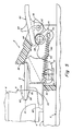
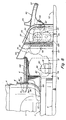
- Figs. 3-8 are partial rear views illustrating a boot stepping into the binding so that the binding moves from the open to the closed position.
- the locking mechanism includes a rocker 12 that mechanically couples the engagement member 6 to the trigger 20.
- the rocker is pivotally mounted, about an axis 18, within a binding cover 50 that is cut away in Figs. 3-6 , but shown in Figs. 7 and 8 .
- the trigger 20 and rocker 12 can be formed from a single molded plastic piece.
- the engagement member 6 is a metal piece that is fixedly attached to the rotatable rocker 12 by a pair of rods 14 best shown in the exploded views of Figs. 9 and 10 .
- the rods 14 extend through holes in the engagement member 6 and rocker 12, and are peened over a washer (not shown) underneath the rocker.
- the fixed engagement member 7 ( Figs. 2 and 9-10 ) can be attached to the binding housing in the same manner.
- the engagement members can alternatively be attached to the binding in a number of other ways.
- the rocker 12, engagement member 6 and trigger 20 are arranged so that when the binding is in the open position, the rider can step into the binding and onto the trigger 20 without interference from the engagement member 6. Furthermore, as the binding moves into the closed position, the member 6 is brought into engagement with the boot recess 54.
- the rocker 12, and consequently the trigger 20 and engagement member 6 that are fixed thereto rotates from the open to the closed position through an angle A ( Figs. 3-4 ) equal to approximately thirty degrees.
- an angle A Figs. 3-4
- the binding be arranged so that when it is in the open position, the rider can step into the binding and onto the trigger 20 without interference from the engagement member 6, and thereby cause the member 6 to be brought into engagement with the boot recess 54 as the boot is advanced into the binding.
- the rocker, latch plate and trigger are preferably dimensioned and configured so that the boot, trigger and engagement member mesh together like a gear when the rider steps into the binding.
- the rocker rotates through an angle of approximately 30° between the open and closed positions, and the bottom surface of the end of the engagement member is angled at approximately 20° to match the lower surface 56 of the boot recess.
- the trigger is slightly longer than the engagement member, and in one embodiment is approximately twenty-five mm long.
- the shape of the sole recess 62 ( Fig. 7 ) on the boot can be manipulated to control the rate at which the engagement member 6 closes as the boot steps down on the trigger.
- the upper surface of the recess is arched from the inside of the foot to the outside, and matches a radius on the upper surface of the trigger.
- the radius for each arc is approximately fifteen mm. The arc on the upper surface of the recess causes the engagement member to close more quickly than if the recess was formed in a rectangular shape.
- the locking mechanism includes a cam 26 that is pivotally mounted within the binding cover 50, about an axis 28, in a manner described below.
- the cam 26 is arranged to enable the rocker to rotate from the open to the closed position. In the closed position, the cam engages the rocker 12 to prevent it and the engagement member 6 fixed thereto from rotating back to the open position unless and until the handle 40 is actuated to open the binding.
- the cam 26 and rocker 12 meet at a contacting surface 36.
- the binding is held in the open position of Fig. 3 by a pair of tension springs 30 (only one of which is shown in phantom in Fig. 3 ) that is attached between the rocker 12 and the cam 26, with the springs extending substantially parallel to one another and being spaced apart about a central axis 9 ( Fig. 9 ) of the engagement member 6.
- the springs are disposed through channels in the rocker 12 and cam 26 and are mounted to rods 32 and 34 respectively disposed in rocker 12 and cam 26.
- the springs 30 act to pull the rods 32 and 34 toward one another, thereby causing the rocker 12 and cam 26 to each be biased for clockwise rotation about their respective axes 18 and 28. Biasing the rocker in the clockwise direction causes the binding to stay in the open position shown in Fig. 3 , with the contact 36 between the inwardly curved surface of the rocker and the outwardly curved surface of the cam limiting the amount of clockwise rotation of the rocker and cam.
- the amount of clockwise rotation of the rocker is further limited by engagement between an upper section 35 of the rocker and an inner surface 112 ( Fig. 10 ) that defines an opening 137 in the binding cover.
- the binding handle 40 is pivotally mounted to the cam 26 about a rod 42, which is mounted through holes in the cam and the handle as discussed below, and provides an axis of rotation for the handle relative to the cam.
- the handle is biased in the clockwise direction by a torsion spring (not shown) wrapped around the rod 42.
- a lip 164 ( Fig. 9 ) of the inner end 44 of the handle is received in a recess 37 ( Fig. 9 ) in the section 35 of the rocker 12.
- the upper surface of the handle adjacent its inner end 44 contacts an inner surface 51 ( Figs. 7-9 ) of the binding cover, which limits clockwise rotation of the handle 40 when the binding is in the open position.
- Fig. 4 illustrates the movement of the locking components as the rider steps into the binding and onto the trigger 20.
- the inner surface of the trigger recess 62 of the rider's boot 4 has contacted and displaced the trigger 20, and consequently the rocker 12 and engagement member 6 fixed thereto, approximately ten degrees in the counterclockwise direction so that the angle A between the bottom of the trigger and the binding plate is approximately twenty degrees.
- the cam 26 is biased in the clockwise direction by the pair of springs 30. Because of the contours of the outer surface of the rocker 12 and the inner surface of the cam 26, rotation of the rocker in the counterclockwise direction permits the cam to rotate in the clockwise direction while remaining in contact with the rocker at 48. If the rider were to lift the boot up away from the binding when in the position shown in Fig. 4 , the force of the tension springs 30 would cause the binding to revert to the open position of Fig. 3 .
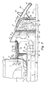
- Fig. 5 illustrates the configuration of the binding when the rider has completed the process of stepping into the binding and the trigger 20 is rotated fully forward to a position wherein it is substantially parallel with the snowboard.
- the bottom surface of the boot interface 8 lies flat on the binding plate 3, with the trigger 20 being received in the recess 64.
- the contact 49 between the cam 26 and the rocker 12 is unstable, in that the cam is not locked into a fixed engagement with the rocker in this configuration.
- the force of the tension springs 30 automatically causes the cam to snap into the position shown in Fig. 6 , in which the binding is configured in an over-center arrangement that locks the engagement member 6 into position in the boot recess 54 to lock the boot into the binding.
- the rocker 12 and cam 26 meet at contact surface 39, wherein the outer curved surface 172 of the rocker mates with the inwardly curved surface 173 of the cam.
- the contact surface 39 is a linear surface that is tangent to each of the two contacting curved surfaces 172 and 173.
- the line of force generated on the rocker and cam by the linear contact surface between them extends normally from the contact surface 39, which is tangent to the curved surfaces.
- the shapes and configurations of the rocker 12 and cam 26 ensure that the binding will remain locked, such that the tension springs 30 are not necessary to keep the binding locked. In this regard, once the binding is locked, it would stay in this position even if the springs were not present.
- the springs 30 need only provide sufficient force to hold the binding open as discussed above in connection with Figs. 2 and 3 , and to snap the cam into the over-center position from the unstable position of Fig. 5 when the trigger is fully depressed.
- Clockwise rotation of the handle 40 in this closed configuration is limited by engagement with an outer section 55 of the cam.
- the section 55 of the cam and the handle arc configured so that when they engage, the handle sits flush with the binding cover along the outer surface of the binding as shown in Fig. 7 .
- This provides a visual cue to the rider that the binding is fully closed and in a ready to ride position.
- the free end 54 of the handle is positioned quite close to the surface 52 of the snowboard (e.g., approximately one quarter inch), thereby minimizing the risk of branches, snow or other objects getting underneath the handle and lifting it inadvertently to release the binding while riding.
- the binding cover 50 is shown in Figs. 7 and 8 , with the rocker 12, cam 26 and the inner surface 51 of the cover being shown in phantom.
- the inner surface 51 of the binding cover includes a flange 53 that serves two purposes. First, the flange acts to limit rotation of the cam 26 in the clockwise direction when the binding is in the closed position. Second, the flange is adapted to be contacted by the cam when the cam snaps into the over-center position, thereby creating a popping sound that provides an audio indication to the rider that the binding is in the locked and ready to ride position.
- the rider lifts the handle 40 to rotate it in the clockwise direction about its pivot axis 42.
- the end 54 of the handle is disposed close to the surface of the snowboard 54 when the binding is in the closed position.
- the handle includes a flange 64 that can be used to rotate the handle to a ready to open position shown in Fig. 8 , making it easier to fit the rider's fingers under the handle.
- the handle includes a torsion spring that biases it in the clockwise direction so that if the rider releases the handle when in the position of Fig. 8 , the handle reverts back to the ready to ride position of Fig. 7 .
- the rider lifts the free end 54 of the handle 40 so that the inner end 44 of the handle contacts the cam 26 at a location 61 that is disposed on the opposite side of the cam pivot axis 28 from the axis 42 about which the handle rotates.
- the engagement with the inner end 44 of the handle causes the cam 26 to rotate counterclockwise about its pivot axis 28.
- the cam Once the cam reaches the bistable position of Fig. 5 , the binding is no longer in an over-center position such that a light lifting force applied on the side of the rider's boot that engages the pivotal engagement member 6 causes the rocker 12 to rotate clockwise into the open position of Fig. 3 .
- the rider can simply step out of the binding.
- the tension springs 30 bias the binding to keep it in the open configuration of Fig. 2 , so that the binding automatically assumes a configuration wherein it is ready to receive the rider's boot.
- the over-center configuration of the binding of the present invention provides secure engagement of the rider's boot, such that the binding will not inadvertently open during riding. Furthermore, a relatively small amount of force is necessary for the rider to open the binding when desired. To rotate the handle to the open position, the rider must only overcome the relatively small force of the torsion spring that biases the handle, and then generate sufficient force to move the cam out of the over-center position.
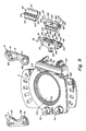
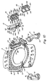
- Figs. 9 and 10 are respectively exploded top and bottom views of the various parts that can be used in implementing one illustrative embodiment of the binding of the present invention.
- the binding cover 50 and binding plate 3 can be formed as a single molded piece of plastic that further includes two substantially hollow posts 72 and 74 for receiving the fixed engagement member 7.
- the engagement member 7 can be a metal plate that is mounted on the posts 72 and 74 via metal rods 76 and 78 that respectively pass through openings in the posts 72 and 74.
- the rods can be peened over and attached via a washer disposed within recesses 80 and 82 ( Fig. 10 ) respectively disposed within the posts 72 and 74.
- the present invention is not limited to any particular technique for attaching the engagement member 7 to the binding, and that other techniques can be used such as press fitting the rods 76 and 78 within bores in the binding housing.
- each engagement member 6 and 7 has a pair of engagement fingers 84 and 86 that is adapted to engage two identical recesses 54 ( Fig. 7 ) formed on the lateral sides of the boot.
- the use of two spaced apart engagement fingers on each side of the boot is advantageous in that it strengthens the engagement between the binding and the boot, particularly when the boot recesses are formed from plastic.
- the present invention is not limited to a binding that uses dual engagement fingers.
- the engagement fingers 84 and 86 are angled upwardly to facilitate engagement with the downwardly angled lower recess surface 56 of the boot when the rider is stepping into the binding.
- the engagement fingers can be formed in any number of alternate configurations to mate with compatible recesses on the boot, and it should be understood that the present invention is not limited to the particular recess and engagement finger configuration shown in the figures.
- the engagement members 6 and 7 are identical to reduce the number of distinct parts in the binding by making it unnecessary to have different engagement member configurations for engaging the inside and outside of the boot.
- Binding cover 50 has a opening 88 for receiving the rocker 12.
- the rocker 12 includes ends 90 and 92 that are adapted to be slidably received in slots 94 and 96 along the inner surface of opening 88.
- Ends 90 and 92 have curved upper surfaces 98 and 100 for mating with corresponding curved surfaces in the slots 94 and 96 (only the curved surface 101 of slot 94 can be seen in the figures).
- the radius of curvature of the surfaces 98 and 100 matches the radius of curvature of the inwardly curved surfaces 101 to permit rotation of the rocker with respect to the binding housing through the angle A ( Fig. 3 ) as the binding moves between the closed and open positions.
- the rocker is held in place in opening 88 by the engagement member 6, which is mounted on the rocker via rods 14 that pass through holes (not shown) in the engagement member and holes 108 and 110 in the rocker, and are fixed underneath the rocker in the same manner as rods 76 and 78 of the fixed engagement member 7 discussed above.
- the rocker 12 essentially hangs from the engagement member 6 via pins 104 and 106.
- the engagement member 6 sits atop a pair of housing surfaces 102 and 103 that are curved to enable the bottom surface 116 of the engagement member to slide over the surfaces through the angles of rotation achieved when the binding moves between the open and closed positions.
- the rocker 12 is placed into the housing opening 88, and then the engagement member 6 is attached to the rocker to movably mount the rocker to the housing.
- the binding housing also includes a pair of slots 124 and 126 for receiving the cam 26.
- Cam 26 includes a pair of ends 120 and 122 that are slidably received in slots 124 and 126, respectively. Ends 120 and 122 include small diameter sections 128 and 130 that are respectively snap fit into circular recesses (not shown) at the top of slots 124 and 126 to establish the cam pivot axis 28 ( Figs 3-8 ).
- the slots 124 and 126 have ramps 132 and 134 adapted to slidably receive smaller diameter sections 128 and 130. The ramps are inclined toward and terminate at a lip before the circular recesses that receive the small diameter sections.
- the binding cover is forced to spread apart slightly to accommodate the sections 128 and 130 until they clear the ramp lips and are snap fit into the circular recesses on the side of the slots 124 and 126.
- An opening 137 in the binding cover provides the area in which the cam surface 138 ( Figs. 9 and 10 ) contacts the rocker surface 140 throughout the range of configurations between the open and closed positions of the binding.
- tension springs 30 ( Fig. 3 ) are attached at one end to the rocker and at the other end to the cam.
- the springs are attached to the trigger side of the rocker and pass through channels 142 and 144 in the rocker.
- the springs are attached to a metal rod (not shown) that is mounted in a groove 146 in the rocker that is disposed below the trigger and intersects both channels 142 and 144.
- the rod can be press fit in the groove 146.
- the springs pass through the rocker channels 142 and 144 and into openings 148 and 150 in the cam 26.
- a bore 152 ( Fig. 10 ) extends through the width of the cam and is adapted to receive a rod (not shown) that intersects openings 148 and 150 and can be press fit in the bore.
- the spring ends are attached to the portions of the rod exposed by the openings 148 and 150.
- the handle 40 is pivotally mounted to the cam 26 via a metal rod 42 ( Figs. 3-6 ) that defines the handle pivot axis.
- the rod passes through holes 154 defined in three sections 155, 156 and 158 of the handle, and through bores 163 in the cam.
- the section 155 of the handle is placed between two outer sections 160 and 162 of the cam, and sections 156 and 158 are respectively positioned outside the cam sections 160 and 162, such that the holes 154 of the three sections of the handle align with the bores 163 in the sections 160 and 162 of the cam.
- a torsion spring (not shown) is wrapped around the rod and acts against the handle surface 166 ( Fig. 10 ) to bias the handle to the ready to ride position as discussed above.
- the binding plate 3 includes an opening 170 for receiving a hold-down disc used to mount the binding to the snowboard in any of a number of rotational orientations relative to the snowboard. Ridges 171 in the plate are adapted to mate with corresponding ridges on the hold down disc.
- a hold-down disc suitable for use with the binding of the present invention is disclosed in U.S. patent no. 5,261,689 , to which the skilled reader is referred for details. However, it should be understood that the present invention is not limited to use with this or any other hold-down disc.
- the binding of the present invention has been described above as being used to engage a soft snowboard boot. Although well adapted to this application, it should be understood that the present invention is not limited in this respect, and that the binding of the present invention can be used to engage hard snowboard boots, ski boots or any of a number of other types of footwear.
- the left binding can simply be a mirror image of the right binding, with the moveable engagement member 6 and handle 40 being disposed on the outside of the foot.
- the movable engagement member and the handle could be configured on the inside of the binding.
- a number of the binding components can be made from metal.
- the present invention is not limited to any particular type of metals, but examples include stainless steel, carbon steel and aluminum.
- the molded plastic components can be formed from any suitable material.
- the molded plastic parts are formed from long fiber glass filled materials, such as nylon, polyurethane, polycarbonate and polypropylene. Long fiber glass filled materials are advantageous in that they maintain their impact strength at relatively cold temperatures where other materials may become brittle.
- the present invention is not limited to use with such materials.
Landscapes
- Health & Medical Sciences (AREA)
- General Health & Medical Sciences (AREA)
- Physical Education & Sports Medicine (AREA)
- Footwear And Its Accessory, Manufacturing Method And Apparatuses (AREA)
- Clamps And Clips (AREA)
Abstract
Claims (33)
- Fixation de planche de surf des neiges (2) pour fixation d'une chaussure de surf des neiges (4) sur une planche de surf des neiges (5), la fixation ayant une position ouverte et une position fermée, la fixation comportant :une base (3) prévue pour recevoir la chaussure de planche de surf des neiges ;un premier élément d'engagement (6), monté de façon pivotante sur la base, prévu pour engager un premier côté latéral de la chaussure de surf des neiges lorsque la fixation est dans la position fermée ; etun ensemble de blocage excentré qui bloque la fixation dans la position fermée, l'ensemble de blocage comprenant :un premier élément de blocage (12), monté de façon pivotante sur la base, qui supporte le premier élément d'engagement et monte le premier élément d'engagement sur la base; etun deuxième élément de blocage (26), monté sur la base pour un mouvement entre une configuration ouverte et une configuration fermée respectivement correspondant aux positions ouverte et fermée de la fixation, le deuxième élément de blocage étant prévu pour engager le premier élément de blocage lorsque le deuxième élément de blocage est dans sa configuration fermée, les premier et deuxième éléments de blocage étant construits et agencés de telle sorte que, lorsque la fixation est dans la position fermée, une force de soulèvement sur le premier élément d'engagement agit afin de maintenir le deuxième élément de blocage dans la configuration fermée, les premier et deuxième éléments de blocage étant montés séparément sur la base, de telle sorte que le premier élément de blocage n'est pas monté sur le deuxième élément de blocage et le deuxième élément de blocage n'est pas monté sur le premier élément de blocage.
- Fixation de planche de surf des neiges selon la revendication 1, dans laquelle le premier élément de blocage a une configuration ouverte et une configuration fermée respectivement qui correspondent aux positions ouverte et fermée de la fixation.
- Fixation de planche de surf des neiges selon la revendication 1 ou 2, dans laquelle :le premier élément de blocage est prévu pour tourner dans une première direction autour d'un premier axe de pivot (18) lorsque le premier élément de blocage se déplace de sa configuration ouverte vers sa configuration fermée ; etle deuxième élément de blocage est prévu pour tourner dans une deuxième direction autour d'un deuxième axe de pivot (28) lorsque le deuxième élément de blocage se déplace de sa configuration ouverte vers sa configuration fermée, la deuxième direction étant opposée à la première direction.
- Fixation de planche de surf des neiges selon l'une quelconque des revendications 1 à 3, comportant en outre un ressort (30) fixé à une première extrémité sur le premier élément de blocage et fixé à une deuxième extrémité sur le deuxième élément de blocage.
- Fixation de planche de surf des neiges selon la revendication 4, dans laquelle le premier élément de blocage est monté de façon pivotante sur la base autour d'un premier axe de pivot (18), dans laquelle le deuxième élément de blocage est monté de façon pivotante autour d'un deuxième axe de pivot (28), et dans laquelle le ressort est fixé au niveau de la deuxième extrémité sur une partie du deuxième élément de blocage qui est disposé sous le deuxième axe de pivot.
- Fixation de planche de surf des neiges selon l'une quelconque des revendications 4 et 5, dans laquelle le deuxième élément de blocage a une configuration instable entre ses configurations ouverte et fermée, et dans laquelle le ressort est prévu pour déplacer le deuxième élément de blocage de sa configuration instable vers sa configuration fermée.
- Fixation de planche de surf des neiges selon l'une quelconque des revendications 4 à 6, dans laquelle le ressort est agencé de telle sorte que, lorsque la fixation est dans la position ouverte, le ressort rappelle la fixation afin de rester dans la position ouverte.
- Fixation de planche de surf des neiges selon l'une quelconque des revendications 1 à 7, dans laquelle le premier côté de la chaussure est le côté médian de la chaussure.
- Fixation de planche de surf des neiges selon l'une quelconque des revendications 1 à 8, dans laquelle le deuxième élément de blocage est prévu pour tourner dans une deuxième direction autour d'un deuxième axe de pivot (28) lorsque le deuxième élément de blocage se déplace de sa configuration ouverte vers sa configuration fermée, et dans laquelle les premier et deuxième éléments de blocage sont agencés de telle sorte que, lorsqu'une force de soulèvement est générée par la chaussure sur le premier élément d'engagement lorsque la fixation est dans la position fermée, la force de soulèvement tend à amener le deuxième élément de blocage à tourner autour du deuxième axe de pivot dans la deuxième direction.
- Fixation de planche de surf des neiges selon l'une quelconque des revendications 2 à 9, dans laquelle le deuxième élément de blocage est construit et agencé afin d'empêcher le premier élément de blocage de se déplacer dans sa configuration ouverte lorsque le deuxième élément de blocage est dans sa configuration fermée.
- Fixation de planche de surf des neiges selon l'une quelconque des revendications 2 à 10, dans laquelle le deuxième élément de blocage est positionné dans sa configuration ouverte lorsque la fixation est dans la position ouverte, et dans laquelle le deuxième élément de blocage engage le premier élément de blocage lorsque chacun se trouve dans sa configuration ouverte.
- Fixation de planche de surf des neiges selon l'une quelconque des revendications 2 à 11, dans laquelle les premier et deuxième éléments de blocage sont agencés afin de maintenir un contact continu lorsque chacun se déplace entre ses configurations ouverte et fermée.
- Fixation de planche de surf des neiges selon l'une quelconque des revendications 1 à 12, dans laquelle le premier élément de blocage comprend une première surface courbe et le deuxième élément de blocage comprend une deuxième surface courbe, les première et deuxième surfaces courbes étant prévues de telle sorte que différentes parties des surfaces correspondent lorsque la fixation se déplace de la position ouverte vers la position fermée.
- Fixation de planche de surf des neiges selon l'une quelconque des revendications 2 à 13, dans laquelle le premier élément de blocage est un basculeur (12) monté de façon pivotante sur la base autour d'un premier axe de pivot (18), et dans laquelle le deuxième élément de blocage est une came (26) montée de façon pivotante sur la base autour d'un deuxième axe de pivot (28).
- Fixation de planche de surf des neiges selon la revendication 14, dans laquelle le basculeur comprend une surface courbée vers l'intérieur et la came comprend une surface courbée vers l'extérieur, et dans laquelle le basculeur et la came sont agencés de telle sorte que, lorsque chacun est dans sa configuration ouverte, une première partie de la surface courbée vers l'intérieur du basculeur vient en contact avec une première partie de la surface courbée vers l'extérieur du basculeur.
- Fixation de planche de surf des neiges selon la revendication 15,'' dans laquelle le basculeur comprend une surface courbée vers l'extérieur adjacente à la surface courbée vers l'intérieur, et dans laquelle le basculeur et la came sont agencés de telle sorte que, lorsque chacun est dans sa configuration fermée, une partie de la surface courbée vers l'extérieur du basculeur vient en contact avec une deuxième partie de la surface courbée vers l'extérieur de la carne.
- Fixation de planche de surf des neiges selon l'une quelconque des revendications 1 à 16, comportant en outre une détente (20), reliée mécaniquement au premier élément de blocage (6), qui est prévue pour être en contact avec la chaussure de surf des neiges (4) lorsque la chaussure rentre dans la fixation et, en réponse à cela, pour amener le premier élément de blocage à se déplacer de sa configuration ouverte vers sa configuration fermée.
- Fixation de planche de surf des neiges selon l'une quelconque des revendications 1 à 17, comportant en outre une poignée (40), reliée mécaniquement au deuxième élément de blocage (26), qui est construite et agencée afin de déplacer le deuxième élément hors de sa configuration fermée.
- Fixation de planche de surf des neiges selon la revendication 18, dans laquelle la poignée est montée de façon pivotante sur le deuxième élément de blocage.
- Fixation de planche de surf des neiges selon l'une quelconque des revendications 18 et 19, dans laquelle la fixation a une position instable entre les positions fermée et ouverte, dans laquelle le deuxième élément de blocage a une configuration instable correspondant à la position instable de la fixation, et dans laquelle la poignée est construite et agencée de telle sorte que la poignée ne vient pas en contact avec le premier élément de blocage lorsque la poignée déplace le deuxième élément de blocage de sa configuration fermée vers sa configuration instable.
- Fixation de planche de surf des neiges selon l'une quelconque des revendications 18 à 20, dans laquelle la poignée et le deuxième élément de blocage sont formés à partir de composants séparés qui sont fixés ensemble.
- Fixation de planche de surf des neiges selon l'une quelconque des revendications 1 à 21; dans laquelle le premier élément d'engagement et le premier élément de blocage sont formés à partir de composants séparés qui sont fixés ensemble.
- Fixation de planche de surf des neiges selon l'une quelconque des revendications 1 à 22, dans laquelle l'ensemble de blocage se compose de seulement deux éléments de blocage mobiles, les deux éléments de blocage mobiles étant le premier élément de blocage et le deuxième élément de blocage.
- Fixation de planche de surf des neiges selon l'une quelconque des revendications 1 à 23, dans laquelle la base a une longueur et une largeur, et dans laquelle le premier élément de blocage est monté de façon pivotante sur la base autour d'un premier axe de pivot (18) qui s'étend sur la longueur de la base.
- Fixation de planche de surf des neiges selon la revendication 24, dans laquelle le deuxième élément de blocage est monté de façon pivotante autour d'un deuxième axe de pivot (28) qui s'étend sur la longueur de la base.
- Fixation de planche de surf des neiges selon la revendication 25, dans laquelle le deuxième axe de pivot est disposé au-dessus du premier axe de pivot.
- Fixation de planche de surf des neiges selon l'une quelconque des revendications 1 à 26, comportant en outre un deuxième élément d'engagement (7), monté sur la base, qui est prévu pour engager un deuxième côté latéral de la chaussure de surf des neiges lorsque la fixation est dans la position fermée.
- Fixation de planche de surf des neiges selon la revendication 27, dans laquelle le deuxième élément d'engagement est fixé sur la base.
- Fixation de planche de surf des neiges selon l'une quelconque des revendications 1 à 28, dans laquelle le premier élément d'engagement comprend une paire d'éléments d'engagement espacés (84, 86) prévus pour engager séparément des première et deuxième sections du premier côté de la chaussure tout en étant espacés d'une troisième section du premier côté de la chaussure disposée entre elles.
- Fixation de planche de surf des neiges selon la revendication 29, en combinaison avec la chaussure de surf des neiges, dans laquelle la chaussure de surf des neiges comprend une paire de renfoncements prévus pour recevoir la paire d'éléments d'engagement espacés, la paire de renfoncements étant séparée par la troisième section du côté de la chaussure, la troisième section du côté de la chaussure étant sans renfoncement.
- Fixation de planche de surf des neiges selon l'une quelconque des revendications 27 à 28, en combinaison avec la chaussure de surf des neiges (4), dans laquelle la chaussure de surf des neiges comprend un premier renfoncement (54) prévu pour recevoir le premier élément d'engagement, et un deuxième renfoncement (54) prévu pour recevoir le deuxième élément d'engagement.
- Combinaison selon l'une quelconque des revendications 30 à 31, dans laquelle la fixation comprend en outre une détente (20), reliée mécaniquement au premier élément de blocage, qui est prévue pour être en contact avec la chaussure de surf des neiges lorsque la chaussure engage la fixation et, en réponse à cela, pour amener le premier élément de blocage à se déplacer de sa configuration ouverte vers sa configuration fermée, et dans laquelle la chaussure de surf des neiges comprend en outre un renfoncement de semelle (62) prévu pour recevoir la détente.
- Combinaison selon l'une quelconque des revendications 31 et 32, dans laquelle une surface inférieure (58) du premier élément d'engagement vient en contact avec une surface inférieure (56) du premier renfoncement lorsque le premier élément d'engagement engage le premier renfoncement, dans laquelle la surface inférieure du premier élément d'engagement est inclinée vers le haut à l'écart de la base lorsque la fixation est dans la position fermée, et dans laquelle la surface inférieure du premier renfoncement est inclinée vers le bas vers la base lorsque la chaussure de surf des neiges est engagée par la fixation dans la position fermée.
Priority Applications (1)
| Application Number | Priority Date | Filing Date | Title |
|---|---|---|---|
| EP99117429A EP0966994B1 (fr) | 1996-05-29 | 1997-05-29 | Fixation automatique de planche des neiges |
Applications Claiming Priority (3)
| Application Number | Priority Date | Filing Date | Title |
|---|---|---|---|
| US08/655,021 US5722680A (en) | 1996-05-29 | 1996-05-29 | Step-in snowboard binding |
| PCT/US1997/011708 WO1997045178A2 (fr) | 1996-05-29 | 1997-05-29 | Fixation rapide pour planche a neige |
| US655021 | 2000-09-05 |
Related Child Applications (1)
| Application Number | Title | Priority Date | Filing Date |
|---|---|---|---|
| EP99117429A Division EP0966994B1 (fr) | 1996-05-29 | 1997-05-29 | Fixation automatique de planche des neiges |
Publications (3)
| Publication Number | Publication Date |
|---|---|
| EP0844902A2 EP0844902A2 (fr) | 1998-06-03 |
| EP0844902B1 EP0844902B1 (fr) | 2000-03-08 |
| EP0844902B2 true EP0844902B2 (fr) | 2008-06-18 |
Family
ID=24627177
Family Applications (2)
| Application Number | Title | Priority Date | Filing Date |
|---|---|---|---|
| EP99117429A Expired - Lifetime EP0966994B1 (fr) | 1996-05-29 | 1997-05-29 | Fixation automatique de planche des neiges |
| EP97932491A Expired - Lifetime EP0844902B2 (fr) | 1996-05-29 | 1997-05-29 | Fixation rapide pour planche a neige |
Family Applications Before (1)
| Application Number | Title | Priority Date | Filing Date |
|---|---|---|---|
| EP99117429A Expired - Lifetime EP0966994B1 (fr) | 1996-05-29 | 1997-05-29 | Fixation automatique de planche des neiges |
Country Status (10)
| Country | Link |
|---|---|
| US (3) | US5722680A (fr) |
| EP (2) | EP0966994B1 (fr) |
| JP (1) | JP3050220U (fr) |
| CN (1) | CN1128644C (fr) |
| AT (1) | AT409936B (fr) |
| AU (1) | AU3593797A (fr) |
| CH (2) | CH689485A5 (fr) |
| DE (1) | DE19780549T1 (fr) |
| HK (1) | HK1018944A1 (fr) |
| WO (1) | WO1997045178A2 (fr) |
Families Citing this family (60)
| Publication number | Priority date | Publication date | Assignee | Title |
|---|---|---|---|---|
| EP0857499B1 (fr) | 1995-01-20 | 2000-05-03 | The Burton Corporation | Fixation d'une chaussure sur une planche de glisse |
| US6126179A (en) | 1995-01-20 | 2000-10-03 | The Burton Corporation | Method and apparatus for interfacing a snowboard boot to a binding |
| US5690351A (en) | 1995-07-21 | 1997-11-25 | Karol; Chris | Snowboard binding system |
| DE19544696A1 (de) * | 1995-11-30 | 1997-06-05 | Marker Deutschland Gmbh | Bindung für Snowboards o. dgl. |
| US6123354A (en) * | 1996-05-29 | 2000-09-26 | Laughlin; James | Step-in snowboard binding |
| DE69712506T2 (de) * | 1996-06-25 | 2002-11-14 | Richard W Berger | Snowboardbindung |
| US6499757B1 (en) * | 1996-06-25 | 2002-12-31 | Richard W. Berger | Wakeboard binding |
| IT1285538B1 (it) * | 1996-10-22 | 1998-06-08 | Twinex S R L | Attacco con bloccaggio rapido della calzatura particolarmente per tavole da neve |
| FR2755027B1 (fr) * | 1996-10-25 | 1999-01-15 | Salomon Sa | Dispositif de retenue d'une chaussure sur une planche de glisse destinee a la pratique du surf sur la neige |
| US6053524A (en) * | 1997-01-08 | 2000-04-25 | The Burton Corporation | Method and apparatus for indicating when a snowboard binding is locked |
| US6648365B1 (en) * | 1997-01-08 | 2003-11-18 | The Burton Corporation | Snowboard binding |
| EP1249259A3 (fr) | 1997-04-18 | 2002-10-30 | The Burton Corporation | Fixation pour planche à neige |
| US5975556A (en) * | 1997-06-18 | 1999-11-02 | Lehmann; Ernest | Snowboard binding |
| FR2767486B1 (fr) * | 1997-08-22 | 1999-10-22 | Salomon Sa | Dispositif de retenue d'une chaussure sur une planche de glisse destinee a la pratique du surf sur neige |
| US5941553A (en) * | 1997-09-15 | 1999-08-24 | Korman; Nathan M. | Boot binding apparatus for a snowboard |
| AUPO954697A0 (en) * | 1997-09-30 | 1997-10-23 | Powder Design Pty. Ltd. | Snowboard safety release binding |
| US6168173B1 (en) * | 1997-11-19 | 2001-01-02 | The Burton Corporation | Snowboard boot with binding interface |
| US6189913B1 (en) | 1997-12-18 | 2001-02-20 | K-2 Corporation | Step-in snowboard binding and boot therefor |
| US6663137B2 (en) | 1998-03-10 | 2003-12-16 | Karlsen Joergen | Snowboard |
| US6105995A (en) * | 1998-04-02 | 2000-08-22 | Zill; Ken | Snowboard binding |
| DE29806599U1 (de) * | 1998-04-09 | 1998-07-16 | Ms Trade Gmbh & Co Kissmark Sp | Snowboard-Einsteigbindung |
| IT1301952B1 (it) * | 1998-07-28 | 2000-07-20 | Piatti Mariadele | Attacco a piastra ad aggancio e sgancio rapido, particolarmente pertavole da neve e simili |
| US6193245B1 (en) * | 1998-09-08 | 2001-02-27 | Douglas Eugene Vensel | Snowboard releasable and reattachable binding system |
| US6231057B1 (en) | 1998-10-09 | 2001-05-15 | The Burton Corporation | Highback with an adjustable shape |
| US6325820B1 (en) * | 1998-11-16 | 2001-12-04 | Endotex Interventional Systems, Inc. | Coiled-sheet stent-graft with exo-skeleton |
| WO2000076337A1 (fr) | 1999-06-15 | 2000-12-21 | The Burton Corporation | Bride pour une chaussure, fixation ou interface de surf des neiges |
| US6416074B1 (en) | 1999-06-15 | 2002-07-09 | The Burton Corporation | Strap for a snowboard boot, binding or interface |
| US6267390B1 (en) | 1999-06-15 | 2001-07-31 | The Burton Corporation | Strap for a snowboard boot, binding or interface |
| GB9914450D0 (en) * | 1999-06-22 | 1999-08-18 | Tindall James J | Releasable fastenings for attaching boots to snowboards |
| FR2801222B1 (fr) * | 1999-11-23 | 2002-01-11 | Emery Sa | Fixation automatique de surf de neige |
| AU2634401A (en) | 2000-01-06 | 2001-07-16 | Burton Corporation, The | Highback formed of multiple materials |
| US6467795B1 (en) | 2000-12-29 | 2002-10-22 | Shimano Inc. | Snowboard binding with highback |
| US20020089150A1 (en) | 2001-01-05 | 2002-07-11 | Musho Edward J. | Snowboard boot with articulating binding interface |
| US6464237B1 (en) | 2001-02-23 | 2002-10-15 | Brian P. Gracie | Snowboard binding |
| US6733031B2 (en) | 2001-04-18 | 2004-05-11 | Shimano, Inc. | Snowboard binding system |
| US6742800B2 (en) | 2001-04-18 | 2004-06-01 | Shimano, Inc. | Snowboard binding system |
| US6536795B2 (en) | 2001-04-18 | 2003-03-25 | Shimano Inc. | Snowboard binding system |
| US6648364B2 (en) | 2001-04-18 | 2003-11-18 | Shimano Inc. | Snowboard binding system |
| US6729641B2 (en) | 2001-04-18 | 2004-05-04 | Shimano Inc. | Snowboard binding system |
| US6637768B2 (en) | 2001-04-18 | 2003-10-28 | Shimano, Inc. | Snowboard binding system |
| US6530590B2 (en) | 2001-04-18 | 2003-03-11 | Shimano Inc. | Snowboard binding system |
| US6684534B2 (en) * | 2001-09-28 | 2004-02-03 | K2 Snowshoes, Inc. | Step-in snowshoe binding system |
| US6722688B2 (en) | 2001-11-21 | 2004-04-20 | The Burton Corporation | Snowboard binding system |
| EP1314462B1 (fr) * | 2001-11-21 | 2005-03-16 | The Burton Corporation | Interface pour la fixation d'une chaussure à une planche de glisse |
| US7048295B2 (en) * | 2002-10-11 | 2006-05-23 | Ken Davies | Automatic, universal boot binding for board sports |
| US20080277904A1 (en) * | 2007-05-11 | 2008-11-13 | Peter Etges | Snowboard binding system |
| WO2008138068A1 (fr) * | 2007-05-16 | 2008-11-20 | Nicholas Fletcher | Fixation de botte |
| US8499474B2 (en) * | 2008-03-05 | 2013-08-06 | Steven Kaufman | Hands-free step-in closure apparatus |
| US8065819B2 (en) * | 2008-03-05 | 2011-11-29 | Steven Kaufman | Hands-free step-in closure apparatus |
| AT11239U1 (de) * | 2008-11-03 | 2010-07-15 | Atomic Austria Gmbh | Schibindung mit einer positionier- und fixiervorrichtung für deren backenkörper |
| AT507821B1 (de) * | 2009-01-19 | 2011-02-15 | Tyrolia Technology Gmbh | Skibindung |
| EP2840921B1 (fr) | 2010-10-27 | 2018-12-12 | Ben C. Debney | Combinaison de système de fixation et de chaussure pour planche à neige |
| US9149711B1 (en) | 2014-11-14 | 2015-10-06 | The Burton Corporation | Snowboard binding and boot |
| US10179272B2 (en) | 2014-11-14 | 2019-01-15 | The Burton Corporation | Snowboard binding and boot |
| US9220970B1 (en) | 2014-11-14 | 2015-12-29 | The Burton Corporation | Snowboard binding and boot |
| US10024493B2 (en) | 2016-08-24 | 2018-07-17 | Swarm Holdings Llc | Speaker mount and assembly and method of disengagement thereof |
| US10171897B2 (en) | 2016-08-24 | 2019-01-01 | Swarm Holdings Llc | Speaker mount and assembly and method of disengagement thereof |
| US11425478B2 (en) | 2018-09-05 | 2022-08-23 | Swarm Holdings Llc. | Speaker mount and assembly |
| US11344084B1 (en) * | 2019-05-09 | 2022-05-31 | Innovative Aerospace | Boot-binding system |
| WO2023092549A1 (fr) * | 2021-11-29 | 2023-06-01 | 孙寅贵 | Fixation de chaussure de snowboard connectée à quatre points pouvant être rapidement mise et retirée |
Family Cites Families (87)
| Publication number | Priority date | Publication date | Assignee | Title |
|---|---|---|---|---|
| US26972A (en) * | 1860-01-31 | Improvement in combined reaping and mowing machines | ||
| US33350A (en) * | 1861-09-24 | Improvement in metallic cars for railroads | ||
| US3140877A (en) * | 1961-07-24 | 1964-07-14 | Richard G Spademan | Safety binding |
| US3271040A (en) * | 1963-10-17 | 1966-09-06 | Richard G Spademan | Safety binding |
| US3280411A (en) * | 1964-07-13 | 1966-10-25 | Robert B Brock | Water ski shoe attachment |
| US3494628A (en) * | 1967-02-24 | 1970-02-10 | Spademan Richard George | Toe piece |
| AT318442B (de) * | 1968-10-15 | 1974-10-25 | Marker Hannes | Lösbare Bindung zwischen Ski und Schuh |
| US3560011A (en) * | 1968-10-22 | 1971-02-02 | Spademan Richard George | Safety binding mechanism |
| US3545103A (en) * | 1969-02-05 | 1970-12-08 | Sports Technology | Closure for boot door |
| AT315040B (de) * | 1972-04-18 | 1974-05-10 | Smolka & Co Wiener Metall | Skibindung |
| US3797841A (en) * | 1972-06-02 | 1974-03-19 | Anderson & Thompson Ski Co | Safety binding |
| US3869136A (en) * | 1972-11-28 | 1975-03-04 | Richard S Jackson | Ski release binding |
| US3824713A (en) * | 1972-12-26 | 1974-07-23 | F Vaccari | Ski boot |
| US3884492A (en) * | 1973-03-15 | 1975-05-20 | Spademan Richard George | Overcenter ski binding mechanism |
| US3900204A (en) * | 1973-06-25 | 1975-08-19 | Robert C Weber | Mono-ski |
| US3852896A (en) * | 1974-03-06 | 1974-12-10 | E Pyzel | Safety release ski boot system |
| US3944240A (en) * | 1974-07-19 | 1976-03-16 | Roland Bodendorfer | Ski binding |
| FR2282823A1 (fr) * | 1974-08-30 | 1976-03-26 | Salomon & Fils F | Chaussure de ski concue pour se deplacer librement apres declenchement dans une fixation comportant une machoire de retenue laterale |
| US3972134A (en) * | 1975-05-05 | 1976-08-03 | Hermann Kastinger | Skiing boot |
| FR2321912A1 (fr) * | 1975-08-28 | 1977-03-25 | Salomon & Fils F | Fixation destinee a retenir une chaussure sur un support, notamment un ski ou une plaque montee sur un ski |
| US4026045A (en) * | 1975-12-03 | 1977-05-31 | Chimera R. & D., Inc. | Boot sole structures |
| USRE33350E (en) * | 1976-04-16 | 1990-09-25 | Ski binding having preset means and detent trigger for said preset means | |
| DE2744758A1 (de) * | 1976-10-18 | 1978-05-24 | Peter Johann P Weninger | Schischuh |
| FR2385346A1 (fr) * | 1977-03-28 | 1978-10-27 | Beyl Jean Joseph Alfred | Ensemble forme par une chaussure de ski et une fixation specialement concue pour recevoir celle-ci |
| US4182525A (en) * | 1977-11-21 | 1980-01-08 | Spademan Richard George | Step-in side-clamp safety ski release system |
| US4395055A (en) * | 1978-03-20 | 1983-07-26 | Spademan Richard George | Ski release side clamping binding with hinged jaw members |
| US4270770A (en) * | 1978-12-07 | 1981-06-02 | Spademan Richard George | Step-in ski binding |
| US4403785A (en) * | 1979-01-15 | 1983-09-13 | Hottel John M | Monoski and releasable bindings for street shoes mountable fore and aft of the ski |
| US4352508A (en) * | 1980-01-07 | 1982-10-05 | Spademan Richard George | Releasable step-in ski binding |
| US4492387A (en) * | 1980-01-07 | 1985-01-08 | Spademan Richard George | Step-in side-clamp safety ski release system |
| IT8061913V0 (it) * | 1980-02-21 | 1980-02-21 | Dolomite Spa | Scarpone da sci con cinturini di chiusura amovibili. |
| US4669202A (en) * | 1984-09-28 | 1987-06-02 | Ottieri Enterprises | Ski boot |
| US4652007A (en) * | 1985-11-15 | 1987-03-24 | David Dennis | Releasable binding system for snowboarding |
| US4741550A (en) * | 1985-11-15 | 1988-05-03 | David Dennis | Releasable binding system for snowboarding |
| US4728116A (en) * | 1986-05-20 | 1988-03-01 | Hill Kurt J | Releasable binding for snowboards |
| FR2628981B1 (fr) * | 1988-03-24 | 1991-01-04 | Gilot Francois | Chaussures a spollers lateraux pour surf des neiges |
| FR2633842B1 (fr) * | 1988-07-07 | 1991-05-17 | Salomon Sa | Fixation de securite a interaction d'un pied sur l'autre pour surf de neige |
| DE3825681C2 (de) * | 1988-07-28 | 1994-04-28 | Look Sa | Sportgleitbrett mit zwei Stiefelbindungen |
| FR2639554B1 (fr) * | 1988-11-25 | 1992-04-30 | Salomon Sa | Fixation de surf de neige |
| FR2640882B1 (fr) * | 1988-12-26 | 1991-04-12 | Salomon Sa | |
| CH678494A5 (en) * | 1989-01-18 | 1991-09-30 | Haldemann Ag | Safety bindings for snow board with tension mechanism - has lateral clamps moved by cables connected to curved pivoting bar which is moved by V=shaped lever |
| FR2644074A1 (fr) * | 1989-03-09 | 1990-09-14 | Fontanille Thierry | Fixation, de securite, d'une chaussure alpine sur un element de glisse, comme, par exemple, un surf |
| US4964649A (en) * | 1989-03-15 | 1990-10-23 | Chamberlin Justin M | Snowboard boot binder attachments |
| US4973073A (en) * | 1989-03-17 | 1990-11-27 | Raines Mark A | Snowboard binding |
| DE3910156A1 (de) * | 1989-03-29 | 1990-10-04 | Peter Schablitzky | Snowboard-sicherheitsbindung |
| FR2646095B1 (fr) * | 1989-04-25 | 1991-08-16 | Salomon Sa | Dispositif de fixation d'une paire de chaussures d'un skieur sur une planche de glisse sur neige |
| CH676205A5 (fr) * | 1989-05-04 | 1990-12-28 | Urs P Meyer | |
| DE3916233A1 (de) * | 1989-05-18 | 1990-11-22 | Hannes Marker | Sicherheitsbindung fuer snowboards |
| DE3918939A1 (de) * | 1989-06-09 | 1990-12-13 | Look Sa | Schneegleitbrett mit zwei bindungen |
| US5028068A (en) * | 1989-09-15 | 1991-07-02 | Donovan Matt J | Quick-action adjustable snow boot binding mounting |
| FR2652753B1 (fr) * | 1989-10-06 | 1993-11-26 | Salomon Sa | Dispositif de fixation des chaussures d'un skieur sur une planche de glisse sur neige telle qu'un monoski ou une planche de surf. |
| DE3939883A1 (de) * | 1989-12-01 | 1991-06-06 | Look Sa | Sicherheitsvorderbacken einer skibindung |
| US4979760A (en) * | 1989-12-26 | 1990-12-25 | Derrah Steven J | Soft boot binding for snow boards |
| US5145202A (en) * | 1990-03-07 | 1992-09-08 | Miller Earl A | Snowboard release binding |
| US5035443A (en) * | 1990-03-27 | 1991-07-30 | Kincheloe Chris V | Releasable snowboard binding |
| CA2030429A1 (fr) * | 1990-11-21 | 1992-05-22 | Gad Shaanan | Fixations pour planche a neige et planche a neige comprenant ces fixations |
| AT402608B (de) * | 1990-12-21 | 1997-07-25 | Varpat Patentverwertung | Kupplungsvorrichtung zwischen einem schischuh kupplungsvorrichtung zwischen einem schischuh und einem schi und einem schi |
| US5172924A (en) * | 1991-03-27 | 1992-12-22 | Barci Robert S | Hard shell boot snowboard bindings and system |
| DE9108513U1 (fr) * | 1991-07-10 | 1991-09-26 | F 2 International Ges.M.B.H., Kirchdorf, At | |
| US5344179A (en) * | 1991-11-28 | 1994-09-06 | Fritschi Ag. Apparatebau | Adjustable length binding system for snowboards having independently variable heel and toe spans |
| US5232241A (en) * | 1992-02-24 | 1993-08-03 | K-2 Corporation | Snow ski with integral binding isolation mounting plate |
| US5188386A (en) * | 1992-02-26 | 1993-02-23 | Schweizer Russell J | Binding mounting apparatus |
| FR2689776B3 (fr) * | 1992-04-09 | 1994-06-17 | Thomas Jerome | Fixation de securite pour surf de neige. |
| DE9215995U1 (de) * | 1992-11-24 | 1993-12-23 | Hildebrand Bernd | Bindung für Snowboard |
| US5299823A (en) * | 1993-01-28 | 1994-04-05 | John Glaser | Snow board binding and method |
| CA2089313A1 (fr) * | 1993-02-11 | 1994-08-12 | Randy Jespersen | Systeme de fixation de chaussure pour planche a neige |
| US5354088A (en) * | 1993-03-15 | 1994-10-11 | Vetter Dennis A | Boot binding coupling for snow boards |
| FR2702935B1 (fr) * | 1993-03-24 | 1995-06-09 | Salomon Sa | Chaussure pour sport de glisse. |
| US5409244A (en) * | 1993-07-12 | 1995-04-25 | Young; Jeffrey A. | Plateless snowboard binding device |
| US5505477A (en) * | 1993-07-19 | 1996-04-09 | K-2 Corporation | Snowboard binding |
| JP2717620B2 (ja) * | 1993-07-27 | 1998-02-18 | 純正化學株式会社 | ジクロログリオキシム有機溶剤溶液の製造法 |
| US5417443A (en) * | 1993-09-01 | 1995-05-23 | Blattner; Jacob A. | Snowboard binding |
| DE4344647C2 (de) * | 1993-12-24 | 1996-07-04 | Christian Breuer | Snowboard-Bindung |
| US5480176A (en) * | 1994-01-18 | 1996-01-02 | Sims; Thomas P. | External mounted binding |
| US5544909A (en) * | 1994-01-27 | 1996-08-13 | The Burton Corporation | Step-in boot binding |
| EP0669147A3 (fr) * | 1994-02-23 | 1996-06-26 | Snowpro Gmbh | Fixation de surf des neiges automatique. |
| AT171U1 (de) * | 1994-05-11 | 1995-04-25 | Techno Circle Produktions Und | Kombination, bestehend aus einem snowboardschuh und einer snowboardbindung |
| US5971420A (en) * | 1994-06-06 | 1999-10-26 | Shimano, Inc. | Snowboard binding |
| DE4424737C1 (de) * | 1994-07-13 | 1996-01-25 | F2 Int Gmbh | Snowboardbindung |
| US5474322A (en) * | 1994-07-21 | 1995-12-12 | Crush Snowboard Products, Inc. | Snowboard binding |
| US5520406A (en) * | 1994-08-18 | 1996-05-28 | Switch Manufacturing | Snowboard binding |
| FR2732239B1 (fr) | 1995-03-29 | 1997-06-06 | Muntzer Emile Jacques | Enrobages bitumineux polyvalents a chaud et a froid |
| EP0857499B1 (fr) * | 1995-01-20 | 2000-05-03 | The Burton Corporation | Fixation d'une chaussure sur une planche de glisse |
| WO1996026774A2 (fr) * | 1995-03-02 | 1996-09-06 | Items International, Inc. | Ensemble fixation pour planche de surf des neiges |
| US5690351A (en) * | 1995-07-21 | 1997-11-25 | Karol; Chris | Snowboard binding system |
| DE19547329A1 (de) * | 1995-12-19 | 1997-06-26 | Marker Deutschland Gmbh | Bindung-Schuh-Kombination für Snowboards o. dgl. |
| DE19544696A1 (de) * | 1995-11-30 | 1997-06-05 | Marker Deutschland Gmbh | Bindung für Snowboards o. dgl. |
-
1996
- 1996-05-29 US US08/655,021 patent/US5722680A/en not_active Expired - Lifetime
-
1997
- 1997-05-29 CH CH00261/98A patent/CH689485A5/fr not_active IP Right Cessation
- 1997-05-29 DE DE19780549T patent/DE19780549T1/de not_active Withdrawn
- 1997-05-29 WO PCT/US1997/011708 patent/WO1997045178A2/fr active IP Right Grant
- 1997-05-29 AU AU35937/97A patent/AU3593797A/en not_active Abandoned
- 1997-05-29 CH CH00604/99A patent/CH690672A5/fr not_active IP Right Cessation
- 1997-05-29 EP EP99117429A patent/EP0966994B1/fr not_active Expired - Lifetime
- 1997-05-29 EP EP97932491A patent/EP0844902B2/fr not_active Expired - Lifetime
- 1997-05-29 AT AT0900597A patent/AT409936B/de not_active IP Right Cessation
- 1997-05-29 CN CN97190598.3A patent/CN1128644C/zh not_active Expired - Fee Related
- 1997-11-18 US US08/972,864 patent/US5957480A/en not_active Expired - Fee Related
- 1997-12-26 JP JP1997011343U patent/JP3050220U/ja not_active Expired - Lifetime
-
1999
- 1999-03-22 HK HK99101145A patent/HK1018944A1/xx not_active IP Right Cessation
- 1999-08-26 US US09/383,306 patent/US6203052B1/en not_active Expired - Fee Related
Also Published As
| Publication number | Publication date |
|---|---|
| EP0966994A3 (fr) | 2000-02-09 |
| DE19780549T1 (de) | 1998-10-01 |
| EP0844902B1 (fr) | 2000-03-08 |
| US6203052B1 (en) | 2001-03-20 |
| US5722680A (en) | 1998-03-03 |
| EP0966994B1 (fr) | 2001-06-27 |
| AU3593797A (en) | 1998-01-05 |
| WO1997045178A3 (fr) | 1998-03-05 |
| CN1194590A (zh) | 1998-09-30 |
| WO1997045178A2 (fr) | 1997-12-04 |
| HK1018944A1 (en) | 2000-01-14 |
| JP3050220U (ja) | 1998-06-30 |
| AT409936B (de) | 2002-12-27 |
| US5957480A (en) | 1999-09-28 |
| CN1128644C (zh) | 2003-11-26 |
| CH690672A5 (fr) | 2000-12-15 |
| EP0966994A2 (fr) | 1999-12-29 |
| CH689485A5 (fr) | 1999-05-14 |
| ATA900597A (de) | 2002-05-15 |
| EP0844902A2 (fr) | 1998-06-03 |
Similar Documents
| Publication | Publication Date | Title |
|---|---|---|
| EP0844902B2 (fr) | Fixation rapide pour planche a neige | |
| US6123354A (en) | Step-in snowboard binding | |
| US6899349B2 (en) | Snowboard binding | |
| EP0751806B1 (fr) | Fixation d'une chaussure sur une planche a neige | |
| US6523851B1 (en) | Binding mechanism for a touring snowboard | |
| EP2002870B1 (fr) | Fixation réglable sans outils pour planche à neige | |
| EP1045724B1 (fr) | Procede et appareil indiquant quand une fixation de planche a neige est verrouillee | |
| WO1996022137A9 (fr) | Fixation d'une chaussure sur une planche a neige | |
| US4893831A (en) | Safety ski binding | |
| US6302428B1 (en) | Snowboard step-in binding | |
| EP0969904B1 (fr) | Fixation pour planche a neige ou similaire | |
| US6460871B1 (en) | Step-in snowboard binding | |
| US6742801B1 (en) | Snowboard boot binding mechanism | |
| US6523852B2 (en) | Step-in snowboard binding | |
| JPS59207174A (ja) | セイフテイ・スキ−バインデイング |
Legal Events
| Date | Code | Title | Description |
|---|---|---|---|
| PUAI | Public reference made under article 153(3) epc to a published international application that has entered the european phase |
Free format text: ORIGINAL CODE: 0009012 |
|
| PUAK | Availability of information related to the publication of the international search report |
Free format text: ORIGINAL CODE: 0009015 |
|
| AK | Designated contracting states |
Kind code of ref document: A2 Designated state(s): FR IT |
|
| 17P | Request for examination filed |
Effective date: 19980128 |
|
| RBV | Designated contracting states (corrected) |
Designated state(s): FR IT |
|
| AK | Designated contracting states |
Kind code of ref document: A3 Designated state(s): AT BE CH DE DK ES FI FR GB GR IE IT LI LU MC NL PT SE |
|
| 17Q | First examination report despatched |
Effective date: 19980525 |
|
| REG | Reference to a national code |
Ref country code: DE Ref legal event code: 8566 |
|
| GRAG | Despatch of communication of intention to grant |
Free format text: ORIGINAL CODE: EPIDOS AGRA |
|
| GRAG | Despatch of communication of intention to grant |
Free format text: ORIGINAL CODE: EPIDOS AGRA |
|
| GRAH | Despatch of communication of intention to grant a patent |
Free format text: ORIGINAL CODE: EPIDOS IGRA |
|
| GRAH | Despatch of communication of intention to grant a patent |
Free format text: ORIGINAL CODE: EPIDOS IGRA |
|
| GRAA | (expected) grant |
Free format text: ORIGINAL CODE: 0009210 |
|
| AK | Designated contracting states |
Kind code of ref document: B1 Designated state(s): FR IT |
|
| ITF | It: translation for a ep patent filed |
Owner name: STUDIO TORTA S.R.L. |
|
| ET | Fr: translation filed | ||
| PLBQ | Unpublished change to opponent data |
Free format text: ORIGINAL CODE: EPIDOS OPPO |
|
| PLBI | Opposition filed |
Free format text: ORIGINAL CODE: 0009260 |
|
| PLBF | Reply of patent proprietor to notice(s) of opposition |
Free format text: ORIGINAL CODE: EPIDOS OBSO |
|
| 26 | Opposition filed |
Opponent name: MARKER DEUTSCHLAND GMBH Effective date: 20001208 |
|
| PLBF | Reply of patent proprietor to notice(s) of opposition |
Free format text: ORIGINAL CODE: EPIDOS OBSO |
|
| PLBF | Reply of patent proprietor to notice(s) of opposition |
Free format text: ORIGINAL CODE: EPIDOS OBSO |
|
| RDAH | Patent revoked |
Free format text: ORIGINAL CODE: EPIDOS REVO |
|
| APAC | Appeal dossier modified |
Free format text: ORIGINAL CODE: EPIDOS NOAPO |
|
| APBQ | Date of receipt of statement of grounds of appeal recorded |
Free format text: ORIGINAL CODE: EPIDOSNNOA3O |
|
| APAA | Appeal reference recorded |
Free format text: ORIGINAL CODE: EPIDOS REFN |
|
| APAH | Appeal reference modified |
Free format text: ORIGINAL CODE: EPIDOSCREFNO |
|
| PGFP | Annual fee paid to national office [announced via postgrant information from national office to epo] |
Ref country code: IT Payment date: 20060531 Year of fee payment: 10 |
|
| APBU | Appeal procedure closed |
Free format text: ORIGINAL CODE: EPIDOSNNOA9O |
|
| PUAH | Patent maintained in amended form |
Free format text: ORIGINAL CODE: 0009272 |
|
| STAA | Information on the status of an ep patent application or granted ep patent |
Free format text: STATUS: PATENT MAINTAINED AS AMENDED |
|
| 27A | Patent maintained in amended form |
Effective date: 20080618 |
|
| AK | Designated contracting states |
Kind code of ref document: B2 Designated state(s): FR IT |
|
| PLAB | Opposition data, opponent's data or that of the opponent's representative modified |
Free format text: ORIGINAL CODE: 0009299OPPO |
|
| PG25 | Lapsed in a contracting state [announced via postgrant information from national office to epo] |
Ref country code: IT Free format text: LAPSE BECAUSE OF NON-PAYMENT OF DUE FEES Effective date: 20070529 |
|
| PGFP | Annual fee paid to national office [announced via postgrant information from national office to epo] |
Ref country code: FR Payment date: 20091201 Year of fee payment: 13 |
|
| PG25 | Lapsed in a contracting state [announced via postgrant information from national office to epo] |
Ref country code: FR Free format text: LAPSE BECAUSE OF NON-PAYMENT OF DUE FEES Effective date: 20100531 |