EP0844475B1 - Particle sizing apparatus - Google Patents
Particle sizing apparatus Download PDFInfo
- Publication number
- EP0844475B1 EP0844475B1 EP97309373A EP97309373A EP0844475B1 EP 0844475 B1 EP0844475 B1 EP 0844475B1 EP 97309373 A EP97309373 A EP 97309373A EP 97309373 A EP97309373 A EP 97309373A EP 0844475 B1 EP0844475 B1 EP 0844475B1
- Authority
- EP
- European Patent Office
- Prior art keywords
- orifice
- signal
- fluid
- predetermined
- pulse
- Prior art date
- Legal status (The legal status is an assumption and is not a legal conclusion. Google has not performed a legal analysis and makes no representation as to the accuracy of the status listed.)
- Expired - Lifetime
Links
- 239000002245 particle Substances 0.000 title claims abstract description 38
- 238000004513 sizing Methods 0.000 title description 4
- 239000012530 fluid Substances 0.000 claims abstract description 37
- 238000005259 measurement Methods 0.000 claims description 31
- 230000001186 cumulative effect Effects 0.000 claims description 7
- 239000000463 material Substances 0.000 claims description 3
- 238000011084 recovery Methods 0.000 claims description 3
- 238000004458 analytical method Methods 0.000 claims description 2
- 230000000694 effects Effects 0.000 claims description 2
- 238000012544 monitoring process Methods 0.000 claims 10
- 230000000737 periodic effect Effects 0.000 claims 1
- 230000001052 transient effect Effects 0.000 claims 1
- 239000000523 sample Substances 0.000 description 45
- 239000003085 diluting agent Substances 0.000 description 26
- BASFCYQUMIYNBI-UHFFFAOYSA-N platinum Chemical compound [Pt] BASFCYQUMIYNBI-UHFFFAOYSA-N 0.000 description 6
- 238000006243 chemical reaction Methods 0.000 description 5
- 238000010586 diagram Methods 0.000 description 5
- 239000003792 electrolyte Substances 0.000 description 4
- 239000000565 sealant Substances 0.000 description 4
- NIXOWILDQLNWCW-UHFFFAOYSA-N acrylic acid group Chemical group C(C=C)(=O)O NIXOWILDQLNWCW-UHFFFAOYSA-N 0.000 description 3
- 239000000853 adhesive Substances 0.000 description 3
- 230000001070 adhesive effect Effects 0.000 description 3
- 230000003321 amplification Effects 0.000 description 3
- 238000013481 data capture Methods 0.000 description 3
- 238000000034 method Methods 0.000 description 3
- 238000003199 nucleic acid amplification method Methods 0.000 description 3
- 229910052697 platinum Inorganic materials 0.000 description 3
- 239000003522 acrylic cement Substances 0.000 description 2
- 238000004140 cleaning Methods 0.000 description 2
- 238000009826 distribution Methods 0.000 description 2
- 239000007788 liquid Substances 0.000 description 2
- 238000004519 manufacturing process Methods 0.000 description 2
- 238000001208 nuclear magnetic resonance pulse sequence Methods 0.000 description 2
- 230000003287 optical effect Effects 0.000 description 2
- 229920000642 polymer Polymers 0.000 description 2
- 230000037452 priming Effects 0.000 description 2
- 238000005086 pumping Methods 0.000 description 2
- 229920002631 room-temperature vulcanizate silicone Polymers 0.000 description 2
- 239000004945 silicone rubber Substances 0.000 description 2
- 230000003068 static effect Effects 0.000 description 2
- 238000012795 verification Methods 0.000 description 2
- KRHYYFGTRYWZRS-UHFFFAOYSA-M Fluoride anion Chemical compound [F-] KRHYYFGTRYWZRS-UHFFFAOYSA-M 0.000 description 1
- 235000014676 Phragmites communis Nutrition 0.000 description 1
- 239000004793 Polystyrene Substances 0.000 description 1
- XUIMIQQOPSSXEZ-UHFFFAOYSA-N Silicon Chemical compound [Si] XUIMIQQOPSSXEZ-UHFFFAOYSA-N 0.000 description 1
- 230000002547 anomalous effect Effects 0.000 description 1
- 230000003466 anti-cipated effect Effects 0.000 description 1
- 238000013459 approach Methods 0.000 description 1
- 230000004323 axial length Effects 0.000 description 1
- 239000003990 capacitor Substances 0.000 description 1
- 239000011248 coating agent Substances 0.000 description 1
- 238000000576 coating method Methods 0.000 description 1
- 230000000052 comparative effect Effects 0.000 description 1
- 230000001143 conditioned effect Effects 0.000 description 1
- 239000002178 crystalline material Substances 0.000 description 1
- 230000002950 deficient Effects 0.000 description 1
- 230000001419 dependent effect Effects 0.000 description 1
- 238000010790 dilution Methods 0.000 description 1
- 239000012895 dilution Substances 0.000 description 1
- 239000002305 electric material Substances 0.000 description 1
- 230000005670 electromagnetic radiation Effects 0.000 description 1
- 238000001914 filtration Methods 0.000 description 1
- 238000009499 grossing Methods 0.000 description 1
- 238000002847 impedance measurement Methods 0.000 description 1
- 230000010354 integration Effects 0.000 description 1
- 230000002093 peripheral effect Effects 0.000 description 1
- 230000002572 peristaltic effect Effects 0.000 description 1
- 239000004033 plastic Substances 0.000 description 1
- 239000004417 polycarbonate Substances 0.000 description 1
- 229920000515 polycarbonate Polymers 0.000 description 1
- 239000002861 polymer material Substances 0.000 description 1
- 229920002223 polystyrene Polymers 0.000 description 1
- 230000002265 prevention Effects 0.000 description 1
- 238000010926 purge Methods 0.000 description 1
- 239000012858 resilient material Substances 0.000 description 1
- 230000000630 rising effect Effects 0.000 description 1
- 239000010979 ruby Substances 0.000 description 1
- 229910001750 ruby Inorganic materials 0.000 description 1
- 229910052594 sapphire Inorganic materials 0.000 description 1
- 239000010980 sapphire Substances 0.000 description 1
- 239000004065 semiconductor Substances 0.000 description 1
- 229910052710 silicon Inorganic materials 0.000 description 1
- 239000010703 silicon Substances 0.000 description 1
- 230000003019 stabilising effect Effects 0.000 description 1
- 238000003860 storage Methods 0.000 description 1
- 238000012360 testing method Methods 0.000 description 1
- 230000009466 transformation Effects 0.000 description 1
- 238000005406 washing Methods 0.000 description 1
- XLYOFNOQVPJJNP-UHFFFAOYSA-N water Substances O XLYOFNOQVPJJNP-UHFFFAOYSA-N 0.000 description 1
Images


Classifications
-
- G—PHYSICS
- G01—MEASURING; TESTING
- G01N—INVESTIGATING OR ANALYSING MATERIALS BY DETERMINING THEIR CHEMICAL OR PHYSICAL PROPERTIES
- G01N15/00—Investigating characteristics of particles; Investigating permeability, pore-volume or surface-area of porous materials
- G01N15/10—Investigating individual particles
- G01N15/1031—Investigating individual particles by measuring electrical or magnetic effects
- G01N15/12—Investigating individual particles by measuring electrical or magnetic effects by observing changes in resistance or impedance across apertures when traversed by individual particles, e.g. by using the Coulter principle
- G01N15/13—Details pertaining to apertures
-
- G—PHYSICS
- G01—MEASURING; TESTING
- G01N—INVESTIGATING OR ANALYSING MATERIALS BY DETERMINING THEIR CHEMICAL OR PHYSICAL PROPERTIES
- G01N15/00—Investigating characteristics of particles; Investigating permeability, pore-volume or surface-area of porous materials
- G01N15/10—Investigating individual particles
- G01N15/1031—Investigating individual particles by measuring electrical or magnetic effects
- G01N15/12—Investigating individual particles by measuring electrical or magnetic effects by observing changes in resistance or impedance across apertures when traversed by individual particles, e.g. by using the Coulter principle
- G01N2015/137—Cleaning
-
- G—PHYSICS
- G01—MEASURING; TESTING
- G01N—INVESTIGATING OR ANALYSING MATERIALS BY DETERMINING THEIR CHEMICAL OR PHYSICAL PROPERTIES
- G01N15/00—Investigating characteristics of particles; Investigating permeability, pore-volume or surface-area of porous materials
- G01N15/10—Investigating individual particles
- G01N15/1031—Investigating individual particles by measuring electrical or magnetic effects
- G01N15/12—Investigating individual particles by measuring electrical or magnetic effects by observing changes in resistance or impedance across apertures when traversed by individual particles, e.g. by using the Coulter principle
- G01N2015/138—Detecting blocking debris
Definitions
- the invention relates to particle or cell sizing and counting apparatus and to methods of operation thereof.
- the invention relates to apparatus which uses a technique of measuring the impedance at an orifice to determine the volume of a particle passing through the orifice.
- GB 1371432 discloses an apparatus for determining the size of particles within a fluid on the basis of a variation in the impedance measured between two electrodes disposed on opposite sides of an orifice through which said fluid flows, wherein blockage of said orifice is determined by comparing a measured rate of occurence of signal pulses caused by particles passing through said orifice with a normally anticipated rate.
- the invention seeks to avoid or at least mitigate problems of the prior art including providing apparatus which detects blockage and optionally deblocks the orifice in the event of partial or complete blockage.
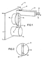
- a particle sizing apparatus 10 comprising a main housing 12 from which protrudes a sample chamber housing 14 having an inlet 16 through which a sample passes into first chamber 52 shown in figure 4. Additionally, a wand guide 18 protrudes from housing 12.
- Wand guide 18 comprises a vertical groove or channel 20 which enables alignment of nozzle 24 of hand-held wand 26 with inlet 16.
- Hand-held wand 26 further comprises a replaceable tip 28, a button 30, fluid inlet pipe 32 and electrical connection 34.
- wand guide 18 comprises a pair of detectors 22 such as optical detectors to determine if wand nozzle 24 is in place within groove 20.
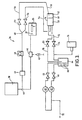
- fluid control system 36 used in apparatus 10.
- a diluent reservoir 38 which can house say three litres of electrolyte for example, is connected along one path to a three-way valve 40 which is connected at one outlet to a syringe drive 42 which can comprise a 12 volt stepper motor for example, and at another outlet is connectable to wand 26 by fluid inlet pipe 32.
- Reservoir 38 is also connected via a T-connector 44 to a diluent sensor 41, which can be an optical device for determining if diluent is present.
- a pump 46 such as a 12 volt DC peristaltic pump, drives diluent to sample chamber housing 14 via a Y-connector 48.
- Y-connector 48 One outlet of Y-connector 48 is connected to tube 50 having a valve 51 such as an electrically operated pinch valve, which controls flow of diluent through tube 50 to a first chamber 52 forming part of sample chamber housing 14.
- the other outlet from Y-connector 48 passes through tube 54 which has a valve 56, again such as an electrically driven pinch valve, which controls flow of fluid through tube 54 into a second chamber 58 of the sample chamber housing 14.
- First and second chambers 52 and 58 respectively, are separated by a flow restrictor 60 having an orifice 63 (see figure 7, 8 and 9).
- Sample chamber 14 is shown in greater detail in figures 4 to 6.
- System 36 further comprises a suction system comprising a pair of vacuum pumps 62.
- Each pump is connected to a vacuum reservoir 64 via a valve 66, such as an electrically driven pinch valve.
- Purge tubes 68 pass almost to the bottom of reservoir 64 thereby to enable expulsion of any liquid in reservoir 64 via at least one of valves 66, pump 62 and outlet 70 thus for disposal.
- Reservoir 64 is further connected via tube 72 to the second chamber 58 of housing 14.
- Tube 72 further comprises a valve 74 such as a pinch valve and a pressure transducer 76 such as a Honeywell Controls type 141PC05G device.
- Reservoir 64 is further connected to the first sample chamber 52 via tube 78 having a valve 80.
- sample chamber housing 14 which preferably comprises an outer shield 15 against electromagnetic radiation such as a metallic casing.
- Inlet 16 leads to first chamber 52 which is separated from second chamber 58 by flow restrictor 60.
- the chambers can be made in a body of inert material such as an acrylic or other plastic.
- the flow restrictor can comprise a crystalline material such as ruby, sapphire, or aluminia or a polymer having a orifice 63.
- the restrictor comprises a piezo-electric material.
- orifice 63 has length L and diameter D, for example a length of 80 microns and diameter of 30 microns is preferred for certain sizes or volumes of particle P which during measurement flow through orifice 63 along direction F.
- Diluent tube 50 enables diluent to pass into first chamber 52 whilst tube 78 enables evacuation of the first chamber.
- tube 54 allows diluent to pass into second chamber 58 and tube 72 enables the evacuation thereof.
- the tubes can comprise different types of passageways, channels and connectors as appropriate.
- tubes 50 and 54 are arranged to direct liquid at the flow restrictor 60. Inlets to sample chamber housing 14 are shown in figure 5.
- a recess 61 can be provided for holding flow restrictor 60 thereby to separate chamber 62 and 58.
- O-rings can also be used to seal the edges of flow restrictor 60.
- electrodes 82 and 84 are shown effectively on opposite sides of flow restrictor 60, i.e. one in each of chambers 52 and 58.
- the electrodes can be made of platinum for example and are connectable to an electronics control system via connector 86.
- the electrodes are mounted in a recess in housing 14 which can be made of acrylic or other polymer material.
- the upper part of the recess, that is adjacent the fluid chambers, is sealed with a water resistant and vacuum seal material such as a silicon based sealant, for example RTV silicone rubber.
- a second stage of adhesive is placed below the sealant to attach the electrode to the walls of the recess.
- a suitable adhesive is a structural acrylic adhesive.
- chamber housing 14 is made from acrylic, the electrodes have an outer platinum coating or are made of platinum and the two-stage sealant and fixing comprises RTV silicone rubber and structural acrylic adhesive.
- chamber housing 14 is easily detachable from main housing 12.
- electrical connector 86 is preferably a simple bayonet-type connector comprising male components adapted to fit into a female socket on housing 12 for example.
- tubes 72, 54 and 78 allow for easy mounting on housing 12 and can for example be the female part of a male/female connection. Accordingly, chamber housing 14 can be attached and removed from main housing 12 in a simple push/pull operation.
- a second embodiment of a flow restrictor 60 wherein orifice 63 is tapered.
- the aperture on one side of restrictor 60 could be 32 to 38 microns in diameter whilst the orifice on the other side could be 30 microns.
- a taper of say 2 to 8 microns in the diameter of the orifice is affected across its length of say 80 microns.
- the narrower orifice faces the second chamber 58 such that in use, as shown in figure a, where the restrictor 60 is made of resilient material, it flexes creating an orifice 63 having approximately parallel sides thereby enabling laminar flow through the orifice.
- the flow restrictor is made of a polymer such as a non-fluoride polycarbonate such as PET or polystyrene.
- the orifice can be laser etched into the flow restrictor.
- second chamber 58 comprises a tapered region 59 which narrows towards flow restrictor 60 (see figure 4).
- tube inlet 54 to chamber 58 is axially aligned with orifice 63 so that fluid passing into chamber 58 is directed to effect turbulence at flow restrictor 60 and possibly to cause reverse flow of diluent through to first chamber 52.
- the tapering of chamber 58 assists in this reverse flow and additionally causes circulation of diluent in chamber 58 assisting in the cleaning thereof.
- a flexible restrictor 60 provides the enhanced clearance configuration shown in figure c.
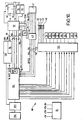
- System 88 comprises an amplifier stage 92 for detecting and amplifying a signal from electrodes 82 and 84.
- a signal power supply unit 94 is provided which generates a plus or minus voltage to be applied across electrodes 82 and 84, for example a voltage of 150 volts is preferred; across the electrodes however this can be somewhat less and can be about 30 volts.
- Amplifier board 92 provides an earth connection to shield 15 around sample chamber housing 14, and is additionally connected to vacuum transducer 76 and a thermocouple or temperature probe 95 such as a National Semi-Conductor type LM35CAH device which can be located for measurement of the diluent temperature in second chamber 58.
- An amplified sample signal is communicated to a 31 ⁇ 2 digit variable potentiometer 96 along line 98 from amplifier stage 92.
- the potentiometer forms part of an attenuator board 100 which enables adjustment of the signal gain as necessary for the selected orifice size and application.
- the output from the attenuator board 100 is fed to a 14 bit analogue to digital converter on measurement board 102.
- the electrode current, vacuum signal and temperature signal are fed along lines 104, 106 and 108 respectively from amplifier board 92 to an 8 bit analogue to digital converter on measurement board 102.
- Measurement board 102 comprises a channel of 500 kHz or 1 MHZ conversions at 14 bits, local storage for a channel of 14 bit data, eight channels of 8 bit (slow) A-D conversion at 100 microsecond conversion, controlling status registers for these devices, 16 bits of digital output control and 16 bits of digital input control.
- Lines 110 and 112 are provided between measurement board 102 and amplifier board 92 respectively to enable reversing of the voltage polarity across the electrodes 82 and 84 and also for commencing and stopping an electrode calibration sequence to be described later.
- a series of digital input/output ports are provided from measurement board 102. These are connected at lines 114 to 120 a stepper motor driver 43 which is in turn connected to syringe stepper motor 42.
- Line 114 carries an opto signal from the syringe drive indicating that the syringe is in its home position. Clock, enable and direction signals are relayed to stepper driver 43 via lines 116, 118 and 120 respectively.
- the other input/output ports on measurement board 102 communicate with driver board 122.
- This board controls the opening and closing of valves 51, 56, 66, 74 and 80. It also controls the diluent pump 46 and vacuum pumps 62.
- the diluent sensor 41 and user wand button 30 are also connected to driver board 122.
- a power supply unit 90 provides requisite voltage to drive the system 88. Also, a programmable device such as a computer 103 is provided to drive and communicate with boards 100 and 102 (or other elements as necessary). A peripheral device such as a display and/or printer 124 is also provided.
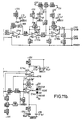
- a particle signal amplification path comprises four low noise op-amps IC10, IC11, IC12 and IC13 having frequency selective components which allow bandpass filtration of the signal to remove DC and high frequency noise.
- Amplifier IC11 has a gain adjustment potentiometer that can be set during manufacture and sealed.
- Amplifier IC13 provides amplifier board 92 with a DC offset adjustment (say -3.2V) using the resistor and potentiometer network R35, R36, VR3 and R37.
- An electrode (82 or 84) is connected at CN1 and is AC coupled to op-amp IC10 via capacitor C38.
- a signal generating voltage source 94 of say 150 volts in this example connects to the signal path at PL 5 and is controlled by reed relay RL1.
- Resistors R23 and R22 form a high impedance path in comparison to the diluent electrolyte through the orifice making the source 94 appear as a constant current generator.
- the amplified signal output at CN2 passes along line 98 to attenuator board 100 shown in figure 10.
- An orifice current signal can be derived from DC current flowing through the chain VR4, RL1, R23, R22, R21, R47 and orifice 63 via CN1.
- the electrode voltage source 94 connects at PL5 and a voltage proportional to the orifice current is expressed across VR4 and R47 and amplified by IC14a. This is further conditioned at amplifier IC14b and output to measurement board 102 via line 104 shown in figure 10.
- first and second chambers 52 and 58 of the sample chamber 14 are washed by alternately opening valve 51 and 56, and valves 80 and 74 respectively, and pumping diluent using pump 46.
- chambers 52 and 58 can be filled and emptied using the vacuum system including pump 62 and tube 72 and 78, for example a series of three times before again filling chamber 62 and 58 to enable an electrical calibration test.
- a series of calibration pulses is applied to one of the electrodes 82 or 84 at CN1 using IC9 shown in Figures 11a and 11b such as a CMOS 555 timer device.
- the output voltage at CN1 can be controlled for example at 12 volt peak to peak thereby to enable an impedance measurement across the orifice which signal might for example be in the order of 1 millivolt for a nominal 30 micron orifice.
- the pulse width can be in the order of 20 to 40 microseconds for frequencies in the order of 15 to 20kHz, or 100 microseconds for 10 kHz.
- the mean pulse height and number of pulses are monitored as part of the calibration verification, a total of three repeated calibration measurements can be attempted before the sequence is aborted and an error condition signal provided to the user for example at a VDU display or similar output device 124 connected to board 102.
- the fluid content of the diluent reservoir 38 is then checked for example using a sensor 41 connected to board 122 shown in figure 10.
- Syringe 42 is then loaded by directing the three way valve 40 to relay fluid from reservoir 38 into syringe 42 and driving stepper motor 43 a calibrated number of steps in order to load the syringe unit with a known volume of diluent such as 1 millilitre.
- the user is then requested to place a disposable sterilised tip 28 on the end of nozzle 24 of wand 26 and press the button 30 to confirm.
- the user places the disposable tip in the sample fluid and again operates button 30 and syringe 42 is driven down a pre-programmed amount thereby to draw sample fluid into the disposable tip 28.
- the user places the sample wand so that nozzle 24 is aligned in groove 20 and tip 28 protrudes into first chamber 52.
- First chamber 52 is emptied by opening valve 80 and using pump 62.
- the operator presses button 30 to initiate a dispense sequence wherein syringe 42 is driven with valve 40 directing fluid through pipe 32 such that the sample and diluent are emitted from wand 26 into first chamber 52.
- detectors 22 determine that nozzle 24 is not in position or has moved away from this position in channel 20, the system waits for the nozzle to be correctly re-positioned. If the sample aspiration, dilution and presentation to chamber 52 is not completed in a predetermined interval, eg 2 minutes, the measurement is aborted and the sample chamber cleaned and the process re-initiated.
- Second chamber 58 is primed with fresh diluent through tube 54 by opening valve 56 and operating pump 46 to ensure that it is substantially full.
- the amount of diluent should be sufficient to enable an electrically conductive path between electrodes 82 and 84 across the flow restrictor 60.
- an initial priming of second chamber 58 is conducted by passing diluent through tube 54, as previously described, causing turbulence in chamber 58. This acts to reduce the possibility of blockage of orifice 63.
- the vacuum reservoir 64 is evacuated of fluid using pumps 62 such that when valve 80 and 74 close a vacuum in the order of 130 mm Hg is established in reservoir 64 as read by transducer 76.
- pumps 62 can be turned off or the associated valve 66 closed, on reaching 90% of the predetermined vacuum pressure and using only one of pump 62 to achieve the predetermined level of vacuum.
- Valve 74 is opened with valve 56 closed and accordingly some sample and diluent is drawn through the orifice 63 of flow restrictor 61, that is between chambers 52 and 58.
- the known voltage is applied to the electrode 82 (or 84).
- the current through the orifice, i.e. between electrodes 82 and 84 is checked at line 104 (see figure 10).
- the current start value or initial value is stored for use in later comparative checks.
- the large DC voltage is removed and a calibrator reference signal applied to electrode 82 (or 84) as previously described.
- the known DC voltage is applied to electrode 82 and the resulting signal amplified between CN 1 and CN2 of Figures 11a and 11b and output from the amplifier board 92 at line 98 is shown in figure 8.
- the pulse signal S has a height, or voltage, determined by the volume of the particle.
- the width W of the pulse is determined by the time for the particle to flow through the orifice, i.e. the flow rate and axial length L of the orifice.
- the signal also has a characteristic background noise N.
- the programmable device 103 sends a signal to measurement board 102 to initiate 14 bit data conversion at 16384 conversions every two microseconds each.
- the gain on the attenuator board 100 can then be adjusted as necessary to bring the signal within a suitable range.
- the data can be sent from measurement board 102 to be stored for example in computer RAM forming part of device 103.
- the signal such as shown in figure 10 is analysed by, for example, applying a smoothing algorithm to the raw data to remove high frequency noise.
- the system detects a pulse signal S by an increasing leading edge over time.
- a minimum number of positive going sample values are required to trigger the search for a corresponding negative going edge thereby to detect a pulse signal S.
- a potential pulse is rejected if a minimum number of negative going samples is not detected after passing through a peak position.
- the system measures the width of the signal as the point half way along the leading edge to a point on a trailing edge where the voltage becomes less than the starting point on the leading edge. Knowing the expected particle flow rates, it is possible to detect falling fluid flow through the orifice by an increasing pulse width. This can be indicative of a partial blockage of orifice 63.
- the pulse height of the signal S can be measured between a net baseline level in the noise N, adjacent signal S and mean or average, peak value of the signal S.
- the peak height can be determined simply from the value at the first positive going point in a detected pulse signals and taking the difference between this value and that at the pulse maximum.
- the pulse area is calculated by integration of signal S and is stored both for a batch and an accumulative histogram for the sample.
- both particles pass through orifice 63 at the same time. This can result in a single pulse representative of the volume of both particles, however, sometimes both pulses are resolvable from one another since a first peak is observed followed by a negative going pulse which does not reach the base line voltage before a second positive going pulse due to the second particle occurs. These incidences can be referred to as primary and secondary coincidence respectively.
- the sample concentration of say a million particles per ml is such that these coincidences very rarely occur, however, pulses from secondary coincidence can still be analysed and form part of the data by extrapolating along the negative going edge of the first pulse to determine a pulse width and also by extrapolating the positive going edge of the second pulse also to determine a pulse width.
- the initial value at the leading edge of the first pulse can be used in the determination of the height of the second pulse.
- each batch of data represents the signals over 32 ms of data capture.
- the number of pulses detected is stored as a current batch value and total for all batches for a given sample (i.e. series of measurements).
- a further store of noise can also be conducted of say any region of noise not containing a pulse signal S for a given a set of captured data.
- a current value derived from that before and after the batch of data is stored as a mean value of the two measurements. The current value is output at PCRT of the circuit shown in figure 9, or line 104 of amplifier board 92 shown in figure 10. The level of vacuum in reservoir 76 is also measured for each batch. Batch data is added to overall sample data to provide cumulative sample histograms.
- measurements of a sample are made over a twenty to thirty second time period during which the sample is caused to flow through orifice 63, preferably a particle at a time.
- the flow can be maintained by repeated evacuation of vacuum reservoir 64 using pump 62 so as to retain an under pressure in the reservoir which draws sample from chamber 62 through to chamber 58, ie. due to the over pressure of atmospheric pressure at inlet 16 to chamber 52.
- three successive evacuations of chamber 64 to a preset pressure might be necessary in a thirty second measurement period, depending on how often a deblocking sequence, described later, is conducted.
- a pulse signal S can approach that of a square wave. This can be monitored by analysing a detected pulse signal S from the time difference between the signal increasing through two distinct and predetermined voltage thresholds above the DC off-set level, and the time for the signal to return back through the two predetermined voltage levels. If the time difference between passing through the lower levels and the upper levels is substantially equal and non-zero then it is indicative of a block having occurred at orifice 63.
- the background noise N is also monitored. By analysing the frequency domain of the noise, following Fourier transformation, it is possible to detect a partial block since the gain of the amplifier is affected and anomalous frequency amplification can be seen. If a factor of say two difference in amplitude is seen in any frequency component then the data can be rejected. Accordingly, the comparison between background noise and an average background noise can indicate partial or complete blockage of orifice 63.
- a first check can be the number of pulses observed in the period of the data capture. If the number of pulses vary significantly in comparison to the mean number of pulses per batch, say by greater than or less than 50%, or alternatively one standard deviation from the mean or slightly more, the data can be rejected. Also, comparison of the mean current value at the start and finish of batch data capture with the start current value can be made. If the difference is greater than say +/- 20% then the batch data can be rejected. Additionally, the mean current value compared to the mean current value for the previous batch of data can be checked. If the difference is more than say an increase of 10% or a decrease of 5%, then the second batch data can be rejected. Additionally, comparison of the noise with static limits can be made.
- a given frequency component varies by a factor of two in comparison with the mean, then this can be taken as defective data.
- Comparison of the individual or mean pulse width for a batch of data with the cumulative mean pulse width is made. If the discrepancy is greater than say 10% then the batch of data can be rejected assuming that a significant number of pulses is detected per batch, say at least 30 and preferably 100 pulses per batch. Additionally, the number of rejected pulses, or square wave pulses is monitored, data can be rejected when observing either one or more rejected pulses in a given batch. In the event of any of these events occurring which leads to data rejection, a deblock sequence is preferably initiated.
- the deblock sequence is initiated by turning off the DC voltage on electrode 82 and applying a pulse sequence which can be the calibration pulse sequence.
- a pulse sequence which can be the calibration pulse sequence.
- a high frequency vibration in the frequency range of say 5 to 20 kHz, is set up within the electrolyte.
- Chamber 58 is also primed by operating pump 46, opening valve 56, whilst valve 74 is also open.
- the priming sequence is terminated after a short time period of say 100 milliseconds, and the calibration or ultrasonic pulses are also turned off.
- the large DC voltage is reapplied to electrode 84 and a time delay of say one second is allowed to elapse to stabilize fluid flow.
- the data measurement sequence is then recommenced as the measurement board is re-initiated, again the attenuator board is adjusted and an initial current value recorded.
- the data received immediately preceding a deblock sequence is subtracted from cumulative data and rejected as being inconsistent.
- the measurement sequence is repeated until the required quantity of fluid has passed through the orifice. This is determined knowing the size of orifice 63, the flow rate from pulse widths and the duration of measurement. Measurement of a sample can also be stopped when the required number of particles within a set range has been measured, or a fatal error occurs and is not rectified such as the orifice current changing and not returning to the value of the start current, the diluent reservoir becoming empty, the data repetition becoming inconsistent, or the base line noise level rising above an acceptable static level.
- the sample Upon completion of a measurement sequence, the sample is evacuated from chamber 52 by opening the valve 80.
- the sample side of the chamber 52 can then be cleaned through a number of rinse cycles by opening valve 51 and pumping at pump 46.
- an intelligent washing sequence is performed whereby the concentration of sample particles from a previous sample is monitored i.e. from the number of particle signals detected in a known measurement volume.
- the apparatus can be calibrated to determine how many rinses are required to clean the chambers following a given concentration of sample.
Landscapes
- Chemical & Material Sciences (AREA)
- General Physics & Mathematics (AREA)
- Pathology (AREA)
- Health & Medical Sciences (AREA)
- Life Sciences & Earth Sciences (AREA)
- Analytical Chemistry (AREA)
- Biochemistry (AREA)
- General Health & Medical Sciences (AREA)
- Dispersion Chemistry (AREA)
- Physics & Mathematics (AREA)
- Immunology (AREA)
- Investigating Or Analyzing Materials By The Use Of Electric Means (AREA)
- Investigating Or Analysing Biological Materials (AREA)
- Seeds, Soups, And Other Foods (AREA)
- Analysing Materials By The Use Of Radiation (AREA)
- Length Measuring Devices By Optical Means (AREA)
- Sampling And Sample Adjustment (AREA)
- Diaphragms For Electromechanical Transducers (AREA)
Applications Claiming Priority (3)
| Application Number | Priority Date | Filing Date | Title |
|---|---|---|---|
| GBGB9624096.5A GB9624096D0 (en) | 1996-11-20 | 1996-11-20 | Apparatus and method of use thereof |
| GB9624096 | 1996-11-20 | ||
| US08/754,823 US6389912B1 (en) | 1996-11-20 | 1996-11-21 | Particle sizing apparatus and method of use thereof |
Publications (3)
| Publication Number | Publication Date |
|---|---|
| EP0844475A2 EP0844475A2 (en) | 1998-05-27 |
| EP0844475A3 EP0844475A3 (en) | 1999-12-08 |
| EP0844475B1 true EP0844475B1 (en) | 2007-01-17 |
Family
ID=26310434
Family Applications (1)
| Application Number | Title | Priority Date | Filing Date |
|---|---|---|---|
| EP97309373A Expired - Lifetime EP0844475B1 (en) | 1996-11-20 | 1997-11-20 | Particle sizing apparatus |
Country Status (7)
| Country | Link |
|---|---|
| US (1) | US6389912B1 (da) |
| EP (1) | EP0844475B1 (da) |
| AT (1) | ATE352031T1 (da) |
| DE (1) | DE69737255T2 (da) |
| DK (1) | DK0844475T3 (da) |
| ES (1) | ES2284178T3 (da) |
| GB (2) | GB9624096D0 (da) |
Cited By (1)
| Publication number | Priority date | Publication date | Assignee | Title |
|---|---|---|---|---|
| US11644410B2 (en) | 2011-01-21 | 2023-05-09 | Labrador Diagnostics Llc | Systems and methods for sample use maximization |
Families Citing this family (26)
| Publication number | Priority date | Publication date | Assignee | Title |
|---|---|---|---|---|
| GB9624096D0 (en) | 1996-11-20 | 1997-01-08 | Microbial Systems Ltd | Apparatus and method of use thereof |
| US6418802B1 (en) * | 1996-11-21 | 2002-07-16 | Michael Anthony Wood | Particle sizing apparatus and method of use thereof |
| GB9810493D0 (en) * | 1998-05-16 | 1998-07-15 | Microbial Systems Ltd | Particle detector system |
| CA2381285C (en) | 1999-08-06 | 2010-04-27 | Ulrik Darling Larsen | Particle characterisation apparatus |
| US6864979B2 (en) * | 2000-12-08 | 2005-03-08 | Horiba, Ltd | Particle size distribution measuring apparatus |
| DE60233708D1 (de) | 2001-11-30 | 2009-10-29 | Sysmex Corp | Teilchenanalysator |
| JP2005534895A (ja) | 2002-06-11 | 2005-11-17 | ケムパック エイ/エス | 異なるタイプの白血球細胞の同時計数のための溶解試薬、カートリッジおよび自動電子細胞カウンタ |
| JP4359452B2 (ja) * | 2003-06-26 | 2009-11-04 | シスメックス株式会社 | 試料分析装置 |
| EP1528387A3 (en) * | 2003-10-27 | 2006-05-24 | Leister Process Technologies | Method for discrimination of particles in a flow cytometer |
| US8028566B2 (en) | 2005-02-10 | 2011-10-04 | Chempaq A/S | Dual sample cartridge and method for characterizing particles in liquid |
| WO2006084472A1 (en) | 2005-02-10 | 2006-08-17 | Chempaq A/S | Dual sample cartridge and method for characterizing particle in liquid |
| NZ564141A (en) | 2005-05-09 | 2011-02-25 | Theranos Inc | Two way communication system for monitoring an analyte |
| US11287421B2 (en) | 2006-03-24 | 2022-03-29 | Labrador Diagnostics Llc | Systems and methods of sample processing and fluid control in a fluidic system |
| US8007999B2 (en) | 2006-05-10 | 2011-08-30 | Theranos, Inc. | Real-time detection of influenza virus |
| US8012744B2 (en) | 2006-10-13 | 2011-09-06 | Theranos, Inc. | Reducing optical interference in a fluidic device |
| US20080113391A1 (en) | 2006-11-14 | 2008-05-15 | Ian Gibbons | Detection and quantification of analytes in bodily fluids |
| US8158430B1 (en) | 2007-08-06 | 2012-04-17 | Theranos, Inc. | Systems and methods of fluidic sample processing |
| ES2447875T3 (es) | 2007-10-02 | 2014-03-13 | Theranos, Inc. | Dispositivos modulares para punto de cuidados y usos de los mismos |
| US8146407B2 (en) * | 2008-06-20 | 2012-04-03 | Beckman Coulter, Inc. | Particle counter with electronic detection of aperture blockage |
| CA3081708C (en) | 2009-10-19 | 2023-10-03 | Theranos Ip Company, Llc | Integrated health data capture and analysis system |
| CN102533536B (zh) * | 2010-12-28 | 2017-04-05 | 深圳迈瑞生物医疗电子股份有限公司 | 计数器组件、鞘液阻抗计数装置及流式细胞分析仪 |
| US9459194B2 (en) | 2013-03-14 | 2016-10-04 | Cardio Metrix | Apparatuses, processes, and systems for measuring particle size distribution and concentration |
| CA3116447A1 (en) | 2018-10-18 | 2020-04-23 | Cellfacts Analytics Limited | A method and apparatus for monitoring microbial contaminants in an industrial process |
| CN111257204B (zh) * | 2018-11-30 | 2021-11-23 | 深圳市帝迈生物技术有限公司 | 用于样本分析仪的微孔堵塞的侦测方法及样本分析仪 |
| CN114543957B (zh) * | 2020-11-26 | 2024-08-16 | 梅特勒-托利多(常州)测量技术有限公司 | 检测信号的实时处理方法及检测器 |
| CN112683949B (zh) * | 2020-11-30 | 2023-09-19 | 深圳市科曼医疗设备有限公司 | 一种宝石孔堵塞的检测方法、系统及存储介质 |
Family Cites Families (38)
| Publication number | Priority date | Publication date | Assignee | Title |
|---|---|---|---|---|
| US2656508A (en) | 1949-08-27 | 1953-10-20 | Wallace H Coulter | Means for counting particles suspended in a fluid |
| US3259891A (en) * | 1964-05-01 | 1966-07-05 | Coulter Electronics | Debris alarm |
| US3395344A (en) | 1964-11-25 | 1968-07-30 | Coulter Electronics | Particle studying apparatus with selfclearing scanner element |
| US3444464A (en) | 1965-11-26 | 1969-05-13 | Coulter Electronics | Multiple aperture fittings for particle analyzing apparatus |
| US3530381A (en) | 1968-01-15 | 1970-09-22 | Coulter Electronics | Voting circuit control apparatus for multiple aperture particle analyzing device |
| US3567321A (en) | 1968-07-22 | 1971-03-02 | Coulter Electronics | Bath for containing and receiving a plurality of aperture tubes |
| DE1806512B2 (de) | 1968-11-02 | 1971-08-12 | Vorrichtung zum klassieren von in einer untersuchungs fluessigkeit suspendierten partikeln | |
| US3678382A (en) | 1970-04-09 | 1972-07-18 | Coulter Electronics | Malfunction detection circuit and method |
| US3739258A (en) | 1971-08-20 | 1973-06-12 | Iit Res Inst | Method and apparatus for detecting and sizing microscopic particles |
| CH544971A (de) | 1972-03-29 | 1973-11-30 | Contraves Ag | Verfahren zum Feststellen von Fehlern beim Zählen von in einem bestimmten Flüssigkeitsvolumen enthaltenen Teilchen |
| GB1371432A (en) | 1972-05-12 | 1974-10-23 | Coulter Electronics | Particle study apparatus having particle resolution means |
| US3783376A (en) * | 1972-06-21 | 1974-01-01 | Becton Dickinson Co | Particle counter having removable aperture slide |
| US3768084A (en) | 1972-07-14 | 1973-10-23 | Becton Dickinson Co | Particle counter having a clog and bubble alarm |
| US3973194A (en) * | 1972-08-07 | 1976-08-03 | Becton, Dickinson And Company | Particle counter |
| DD102215A1 (da) | 1973-02-02 | 1973-12-12 | ||
| US3863056A (en) | 1973-06-29 | 1975-01-28 | Coulter Electronics | Method and apparatus for multichannel voting |
| US3930736A (en) | 1974-07-01 | 1976-01-06 | Coulter Electronics, Inc. | Aperture tube with attached thief |
| US3963984A (en) | 1974-11-04 | 1976-06-15 | Coulter Electronics, Inc. | Method and system for cleaning an aperture in a particle study device |
| US4014611A (en) | 1975-04-30 | 1977-03-29 | Coulter Electronics, Inc. | Aperture module for use in particle testing apparatus |
| US4078211A (en) | 1976-09-29 | 1978-03-07 | Coulter Electronics, Inc. | Method and apparatus for balancing particle detecting signals generated in a particle study device having multiple apertures |
| IL53921A (en) | 1977-02-15 | 1979-12-30 | Coulter Electronics | Electronic particle sensing aperture module with perforated electrode |
| US4290011A (en) | 1978-05-18 | 1981-09-15 | Particle Data, Inc. | Particle length and volume comeasurement with controlled orientation |
| US4491786A (en) | 1978-09-13 | 1985-01-01 | Coulter Electronics, Inc. | Transducer for measuring particles suspended in a fluid |
| FR2472183B1 (fr) | 1979-12-12 | 1986-03-07 | Coulter Electronics | Procede de nettoyage d'une ouverture pour un dispositif d'etude de particules et appareil pour la mise en oeuvre de ce procede |
| US4412175A (en) | 1981-04-30 | 1983-10-25 | Coulter Electronics, Inc. | Debris alarm |
| US4450435A (en) * | 1981-11-30 | 1984-05-22 | Bobby Dencil James | Analog debris alarm |
| US4600880A (en) | 1983-03-03 | 1986-07-15 | Limca Research Inc. | Apparatus for the detection and measurement of particulates in molten metal |
| US4564803A (en) | 1983-08-29 | 1986-01-14 | Coulter Corporation | Method and apparatus for removing foreign matter from a flow cell of a particle study device |
| GB8410500D0 (en) | 1984-04-25 | 1984-05-31 | Orbec Ltd | Monitoring particles in liquids |
| FR2569477B1 (fr) | 1984-08-24 | 1987-01-02 | Descartes Universite Rene | Appareil et procede pour la determination de la deformabilite des globules rouges du sang |
| GB8505047D0 (en) | 1985-02-27 | 1985-03-27 | Alcan Int Ltd | Studying particles |
| US4775833A (en) | 1986-10-03 | 1988-10-04 | Coulter Electronics, Inc. | Lodged debris detector for a particle analyzer |
| DE3786657D1 (de) | 1987-02-17 | 1993-08-26 | Ratcom Inc | Durchflusszytometrie. |
| US4977517A (en) | 1988-09-21 | 1990-12-11 | Toni Diagnostics, Inc. | Leak and clog detection and removal system for use with particle counters |
| WO1992001934A1 (en) | 1990-07-17 | 1992-02-06 | Pasula Mark J | Blood testing apparatus |
| JP2965688B2 (ja) * | 1990-11-30 | 1999-10-18 | シスメックス株式会社 | 粒子検出装置 |
| JPH07301595A (ja) | 1994-05-09 | 1995-11-14 | Toa Medical Electronics Co Ltd | 粒子測定装置およびその粒子測定方法 |
| GB9624096D0 (en) | 1996-11-20 | 1997-01-08 | Microbial Systems Ltd | Apparatus and method of use thereof |
-
1996
- 1996-11-20 GB GBGB9624096.5A patent/GB9624096D0/en active Pending
- 1996-11-21 US US08/754,823 patent/US6389912B1/en not_active Expired - Fee Related
-
1997
- 1997-11-20 ES ES97309373T patent/ES2284178T3/es not_active Expired - Lifetime
- 1997-11-20 GB GB9724611A patent/GB2319618B/en not_active Expired - Fee Related
- 1997-11-20 EP EP97309373A patent/EP0844475B1/en not_active Expired - Lifetime
- 1997-11-20 DK DK97309373T patent/DK0844475T3/da active
- 1997-11-20 AT AT97309373T patent/ATE352031T1/de not_active IP Right Cessation
- 1997-11-20 DE DE69737255T patent/DE69737255T2/de not_active Expired - Lifetime
Cited By (1)
| Publication number | Priority date | Publication date | Assignee | Title |
|---|---|---|---|---|
| US11644410B2 (en) | 2011-01-21 | 2023-05-09 | Labrador Diagnostics Llc | Systems and methods for sample use maximization |
Also Published As
| Publication number | Publication date |
|---|---|
| GB9724611D0 (en) | 1998-01-21 |
| EP0844475A3 (en) | 1999-12-08 |
| DE69737255D1 (de) | 2007-03-08 |
| EP0844475A2 (en) | 1998-05-27 |
| DK0844475T3 (da) | 2007-05-21 |
| GB9624096D0 (en) | 1997-01-08 |
| GB2319618B (en) | 2000-08-23 |
| GB2319618A (en) | 1998-05-27 |
| US6389912B1 (en) | 2002-05-21 |
| ATE352031T1 (de) | 2007-02-15 |
| ES2284178T3 (es) | 2007-11-01 |
| DE69737255T2 (de) | 2007-10-31 |
Similar Documents
| Publication | Publication Date | Title |
|---|---|---|
| EP0844475B1 (en) | Particle sizing apparatus | |
| US6418802B1 (en) | Particle sizing apparatus and method of use thereof | |
| US6909269B2 (en) | Particle detector and particle analyzer employing the same | |
| US4651555A (en) | Apparatus for detecting discontinuities in a fluid stream | |
| EP1080362B1 (en) | Particle detector system | |
| US3973189A (en) | Hematology system | |
| JPH07301586A (ja) | 試料処理装置 | |
| EP0527059B1 (en) | Method for agitating and sampling a liquid specimen | |
| US6417658B1 (en) | Flow cell for particle analyzer using electrical sensing zone method | |
| GB2337599A (en) | Particle sizing apparatus | |
| JPH0261709B2 (da) | ||
| US6534965B2 (en) | Particle signal processing apparatus and particle measurement apparatus using same | |
| US4564803A (en) | Method and apparatus for removing foreign matter from a flow cell of a particle study device | |
| US3973194A (en) | Particle counter | |
| JPH0627120A (ja) | 閉塞検出付分注装置 | |
| JPH06109745A (ja) | ノズルの詰まり検知装置 | |
| JP2784694B2 (ja) | 自動化学分析装置 | |
| JP2001264233A (ja) | 粒子測定装置 | |
| CA1248776A (en) | Method and apparatus for removing foreign matter from a flow cell of a particle study device | |
| JPH0263183B2 (da) | ||
| JPS6225713Y2 (da) | ||
| JPS6025736B2 (ja) | 光学濁度測定装置の自動洗浄制御方法およびその装置 | |
| GB2065311A (en) | Particle study device aperture cleaning systems and methods | |
| JPH07333186A (ja) | 液体濃度測定装置 | |
| JPS5883231A (ja) | 赤血球の特性を測定する方法およびその装置 |
Legal Events
| Date | Code | Title | Description |
|---|---|---|---|
| PUAI | Public reference made under article 153(3) epc to a published international application that has entered the european phase |
Free format text: ORIGINAL CODE: 0009012 |
|
| AK | Designated contracting states |
Kind code of ref document: A2 Designated state(s): AT BE CH DE DK ES FI FR GB GR IE IT LI NL PT SE |
|
| AX | Request for extension of the european patent |
Free format text: AL;LT;LV;MK;RO;SI |
|
| PUAL | Search report despatched |
Free format text: ORIGINAL CODE: 0009013 |
|
| AK | Designated contracting states |
Kind code of ref document: A3 Designated state(s): AT BE CH DE DK ES FI FR GB GR IE IT LI LU MC NL PT SE |
|
| AX | Request for extension of the european patent |
Free format text: AL;LT;LV;MK;RO;SI |
|
| 17P | Request for examination filed |
Effective date: 20000606 |
|
| AKX | Designation fees paid |
Free format text: AT BE CH DE DK ES FI FR GB GR IE IT LI NL PT SE |
|
| 17Q | First examination report despatched |
Effective date: 20030620 |
|
| GRAP | Despatch of communication of intention to grant a patent |
Free format text: ORIGINAL CODE: EPIDOSNIGR1 |
|
| GRAS | Grant fee paid |
Free format text: ORIGINAL CODE: EPIDOSNIGR3 |
|
| GRAA | (expected) grant |
Free format text: ORIGINAL CODE: 0009210 |
|
| AK | Designated contracting states |
Kind code of ref document: B1 Designated state(s): AT BE CH DE DK ES FI FR GB GR IE IT LI NL PT SE |
|
| PG25 | Lapsed in a contracting state [announced via postgrant information from national office to epo] |
Ref country code: FI Free format text: LAPSE BECAUSE OF FAILURE TO SUBMIT A TRANSLATION OF THE DESCRIPTION OR TO PAY THE FEE WITHIN THE PRESCRIBED TIME-LIMIT Effective date: 20070117 |
|
| REG | Reference to a national code |
Ref country code: GB Ref legal event code: FG4D |
|
| REG | Reference to a national code |
Ref country code: CH Ref legal event code: EP |
|
| REG | Reference to a national code |
Ref country code: IE Ref legal event code: FG4D |
|
| REF | Corresponds to: |
Ref document number: 69737255 Country of ref document: DE Date of ref document: 20070308 Kind code of ref document: P |
|
| REG | Reference to a national code |
Ref country code: PT Ref legal event code: SC4A Free format text: AVAILABILITY OF NATIONAL TRANSLATION Effective date: 20070417 |
|
| REG | Reference to a national code |
Ref country code: SE Ref legal event code: TRGR |
|
| REG | Reference to a national code |
Ref country code: DK Ref legal event code: T3 |
|
| REG | Reference to a national code |
Ref country code: PT Ref legal event code: PC4A Owner name: CELLFACTS INSTRUMENTS LIMITED, GB Effective date: 20070628 |
|
| RAP2 | Party data changed (patent owner data changed or rights of a patent transferred) |
Owner name: CELLFACTS INSTRUMENTS LIMITED |
|
| ET | Fr: translation filed | ||
| REG | Reference to a national code |
Ref country code: CH Ref legal event code: PUE Owner name: CELLFACTS INSTRUMENTS LIMITED Free format text: MICROBIAL SYSTEMS LIMITED#THE VISCOUNT CENTRE, UNIVERSITY OF WARWICK SCIENCE PARK, MILBURN HILL ROAD#COVENTRY CV4 7HS (GB) -TRANSFER TO- CELLFACTS INSTRUMENTS LIMITED#THE VISCOUNT CENTRE UNIVERSITY OF WARWICK SCIENCE PARK MILBURN HILL ROAD#COVENTRY CV4 7HS (GB) Ref country code: CH Ref legal event code: NV Representative=s name: KELLER & PARTNER PATENTANWAELTE AG |
|
| NLT2 | Nl: modifications (of names), taken from the european patent patent bulletin |
Owner name: CELLFACTS INSTRUMENTS LIMITED Effective date: 20070808 |
|
| REG | Reference to a national code |
Ref country code: ES Ref legal event code: FG2A Ref document number: 2284178 Country of ref document: ES Kind code of ref document: T3 |
|
| PLBE | No opposition filed within time limit |
Free format text: ORIGINAL CODE: 0009261 |
|
| STAA | Information on the status of an ep patent application or granted ep patent |
Free format text: STATUS: NO OPPOSITION FILED WITHIN TIME LIMIT |
|
| 26N | No opposition filed |
Effective date: 20071018 |
|
| BECA | Be: change of holder's address |
Owner name: CELLFACTS INSTRUMENTS LTDTHE VISCOUNT CENTRE, UNIV Effective date: 20070117 |
|
| BECH | Be: change of holder |
Owner name: CELLFACTS INSTRUMENTS LTD Effective date: 20070117 |
|
| PG25 | Lapsed in a contracting state [announced via postgrant information from national office to epo] |
Ref country code: GR Free format text: LAPSE BECAUSE OF FAILURE TO SUBMIT A TRANSLATION OF THE DESCRIPTION OR TO PAY THE FEE WITHIN THE PRESCRIBED TIME-LIMIT Effective date: 20070418 |
|
| NLS | Nl: assignments of ep-patents |
Owner name: CELLFACTS INSTRUMENTS LIMITED Effective date: 20080522 |
|
| PGFP | Annual fee paid to national office [announced via postgrant information from national office to epo] |
Ref country code: IE Payment date: 20081120 Year of fee payment: 12 |
|
| PGFP | Annual fee paid to national office [announced via postgrant information from national office to epo] |
Ref country code: PT Payment date: 20081120 Year of fee payment: 12 Ref country code: ES Payment date: 20081127 Year of fee payment: 12 |
|
| PGFP | Annual fee paid to national office [announced via postgrant information from national office to epo] |
Ref country code: BE Payment date: 20081126 Year of fee payment: 12 Ref country code: SE Payment date: 20081120 Year of fee payment: 12 Ref country code: IT Payment date: 20081126 Year of fee payment: 12 |
|
| PGFP | Annual fee paid to national office [announced via postgrant information from national office to epo] |
Ref country code: NL Payment date: 20090527 Year of fee payment: 12 |
|
| REG | Reference to a national code |
Ref country code: PT Ref legal event code: MM4A Free format text: LAPSE DUE TO NON-PAYMENT OF FEES Effective date: 20100520 |
|
| BERE | Be: lapsed |
Owner name: CELLFACTS INSTRUMENTS LTD Effective date: 20091130 |
|
| REG | Reference to a national code |
Ref country code: NL Ref legal event code: V1 Effective date: 20100601 |
|
| EUG | Se: european patent has lapsed | ||
| PG25 | Lapsed in a contracting state [announced via postgrant information from national office to epo] |
Ref country code: PT Free format text: LAPSE BECAUSE OF NON-PAYMENT OF DUE FEES Effective date: 20100520 |
|
| PGFP | Annual fee paid to national office [announced via postgrant information from national office to epo] |
Ref country code: FR Payment date: 20100603 Year of fee payment: 13 Ref country code: DK Payment date: 20100512 Year of fee payment: 13 |
|
| PGFP | Annual fee paid to national office [announced via postgrant information from national office to epo] |
Ref country code: DE Payment date: 20100511 Year of fee payment: 13 Ref country code: AT Payment date: 20100513 Year of fee payment: 13 |
|
| PG25 | Lapsed in a contracting state [announced via postgrant information from national office to epo] |
Ref country code: NL Free format text: LAPSE BECAUSE OF NON-PAYMENT OF DUE FEES Effective date: 20100601 Ref country code: IE Free format text: LAPSE BECAUSE OF NON-PAYMENT OF DUE FEES Effective date: 20091120 Ref country code: BE Free format text: LAPSE BECAUSE OF NON-PAYMENT OF DUE FEES Effective date: 20091130 |
|
| PGFP | Annual fee paid to national office [announced via postgrant information from national office to epo] |
Ref country code: CH Payment date: 20100517 Year of fee payment: 13 |
|
| PG25 | Lapsed in a contracting state [announced via postgrant information from national office to epo] |
Ref country code: IT Free format text: LAPSE BECAUSE OF NON-PAYMENT OF DUE FEES Effective date: 20091120 |
|
| REG | Reference to a national code |
Ref country code: ES Ref legal event code: FD2A Effective date: 20110408 |
|
| PG25 | Lapsed in a contracting state [announced via postgrant information from national office to epo] |
Ref country code: SE Free format text: LAPSE BECAUSE OF NON-PAYMENT OF DUE FEES Effective date: 20091121 |
|
| REG | Reference to a national code |
Ref country code: CH Ref legal event code: PL |
|
| REG | Reference to a national code |
Ref country code: DK Ref legal event code: EBP |
|
| GBPC | Gb: european patent ceased through non-payment of renewal fee |
Effective date: 20101120 |
|
| PG25 | Lapsed in a contracting state [announced via postgrant information from national office to epo] |
Ref country code: LI Free format text: LAPSE BECAUSE OF NON-PAYMENT OF DUE FEES Effective date: 20101130 Ref country code: CH Free format text: LAPSE BECAUSE OF NON-PAYMENT OF DUE FEES Effective date: 20101130 Ref country code: ES Free format text: LAPSE BECAUSE OF NON-PAYMENT OF DUE FEES Effective date: 20110324 |
|
| REG | Reference to a national code |
Ref country code: FR Ref legal event code: ST Effective date: 20110801 |
|
| PG25 | Lapsed in a contracting state [announced via postgrant information from national office to epo] |
Ref country code: AT Free format text: LAPSE BECAUSE OF NON-PAYMENT OF DUE FEES Effective date: 20101120 |
|
| REG | Reference to a national code |
Ref country code: DE Ref legal event code: R119 Ref document number: 69737255 Country of ref document: DE Effective date: 20110601 Ref country code: DE Ref legal event code: R119 Ref document number: 69737255 Country of ref document: DE Effective date: 20110531 |
|
| PG25 | Lapsed in a contracting state [announced via postgrant information from national office to epo] |
Ref country code: ES Free format text: LAPSE BECAUSE OF NON-PAYMENT OF DUE FEES Effective date: 20091121 Ref country code: DE Free format text: LAPSE BECAUSE OF NON-PAYMENT OF DUE FEES Effective date: 20110531 |
|
| PG25 | Lapsed in a contracting state [announced via postgrant information from national office to epo] |
Ref country code: DK Free format text: LAPSE BECAUSE OF NON-PAYMENT OF DUE FEES Effective date: 20101130 Ref country code: FR Free format text: LAPSE BECAUSE OF NON-PAYMENT OF DUE FEES Effective date: 20101130 |
|
| PG25 | Lapsed in a contracting state [announced via postgrant information from national office to epo] |
Ref country code: GB Free format text: LAPSE BECAUSE OF NON-PAYMENT OF DUE FEES Effective date: 20101120 |
|
| REG | Reference to a national code |
Ref country code: GB Ref legal event code: S28 Free format text: APPLICATION FILED |
|
| REG | Reference to a national code |
Ref country code: GB Ref legal event code: 732E Free format text: REGISTERED BETWEEN 20120726 AND 20120801 |
|
| REG | Reference to a national code |
Ref country code: GB Ref legal event code: S28 Free format text: RESTORATION ALLOWED Effective date: 20130220 |
|
| PGFP | Annual fee paid to national office [announced via postgrant information from national office to epo] |
Ref country code: GB Payment date: 20130213 Year of fee payment: 16 |
|
| GBPC | Gb: european patent ceased through non-payment of renewal fee |
Effective date: 20131120 |
|
| PG25 | Lapsed in a contracting state [announced via postgrant information from national office to epo] |
Ref country code: GB Free format text: LAPSE BECAUSE OF NON-PAYMENT OF DUE FEES Effective date: 20131120 |