EP0843990B1 - Ballonkatheter und Vorrichtung zum Setzen eines Stents - Google Patents
Ballonkatheter und Vorrichtung zum Setzen eines Stents Download PDFInfo
- Publication number
- EP0843990B1 EP0843990B1 EP96203188A EP96203188A EP0843990B1 EP 0843990 B1 EP0843990 B1 EP 0843990B1 EP 96203188 A EP96203188 A EP 96203188A EP 96203188 A EP96203188 A EP 96203188A EP 0843990 B1 EP0843990 B1 EP 0843990B1
- Authority
- EP
- European Patent Office
- Prior art keywords
- balloon
- balloon catheter
- covering sleeve
- catheter according
- catheter shaft
- Prior art date
- Legal status (The legal status is an assumption and is not a legal conclusion. Google has not performed a legal analysis and makes no representation as to the accuracy of the status listed.)
- Expired - Lifetime
Links
- 230000010339 dilation Effects 0.000 claims description 13
- 239000000463 material Substances 0.000 claims description 5
- 230000001419 dependent effect Effects 0.000 claims description 2
- 238000009954 braiding Methods 0.000 claims 1
- 239000010903 husk Substances 0.000 claims 1
- 230000002787 reinforcement Effects 0.000 abstract description 12
- 208000031481 Pathologic Constriction Diseases 0.000 description 4
- 208000027418 Wounds and injury Diseases 0.000 description 4
- 230000006378 damage Effects 0.000 description 3
- 238000004519 manufacturing process Methods 0.000 description 3
- 230000036262 stenosis Effects 0.000 description 3
- 208000037804 stenosis Diseases 0.000 description 3
- 230000002792 vascular Effects 0.000 description 3
- 208000014674 injury Diseases 0.000 description 2
- 239000000853 adhesive Substances 0.000 description 1
- 230000001070 adhesive effect Effects 0.000 description 1
- 210000004204 blood vessel Anatomy 0.000 description 1
- 238000005253 cladding Methods 0.000 description 1
- 238000006073 displacement reaction Methods 0.000 description 1
- 238000002513 implantation Methods 0.000 description 1
- 239000012744 reinforcing agent Substances 0.000 description 1
- 230000008719 thickening Effects 0.000 description 1
Images

Classifications
-
- A—HUMAN NECESSITIES
- A61—MEDICAL OR VETERINARY SCIENCE; HYGIENE
- A61M—DEVICES FOR INTRODUCING MEDIA INTO, OR ONTO, THE BODY; DEVICES FOR TRANSDUCING BODY MEDIA OR FOR TAKING MEDIA FROM THE BODY; DEVICES FOR PRODUCING OR ENDING SLEEP OR STUPOR
- A61M25/00—Catheters; Hollow probes
- A61M25/10—Balloon catheters
-
- A—HUMAN NECESSITIES
- A61—MEDICAL OR VETERINARY SCIENCE; HYGIENE
- A61F—FILTERS IMPLANTABLE INTO BLOOD VESSELS; PROSTHESES; DEVICES PROVIDING PATENCY TO, OR PREVENTING COLLAPSING OF, TUBULAR STRUCTURES OF THE BODY, e.g. STENTS; ORTHOPAEDIC, NURSING OR CONTRACEPTIVE DEVICES; FOMENTATION; TREATMENT OR PROTECTION OF EYES OR EARS; BANDAGES, DRESSINGS OR ABSORBENT PADS; FIRST-AID KITS
- A61F2/00—Filters implantable into blood vessels; Prostheses, i.e. artificial substitutes or replacements for parts of the body; Appliances for connecting them with the body; Devices providing patency to, or preventing collapsing of, tubular structures of the body, e.g. stents
- A61F2/95—Instruments specially adapted for placement or removal of stents or stent-grafts
- A61F2/958—Inflatable balloons for placing stents or stent-grafts
-
- A—HUMAN NECESSITIES
- A61—MEDICAL OR VETERINARY SCIENCE; HYGIENE
- A61M—DEVICES FOR INTRODUCING MEDIA INTO, OR ONTO, THE BODY; DEVICES FOR TRANSDUCING BODY MEDIA OR FOR TAKING MEDIA FROM THE BODY; DEVICES FOR PRODUCING OR ENDING SLEEP OR STUPOR
- A61M25/00—Catheters; Hollow probes
- A61M25/10—Balloon catheters
- A61M2025/1043—Balloon catheters with special features or adapted for special applications
- A61M2025/1068—Balloon catheters with special features or adapted for special applications having means for varying the length or diameter of the deployed balloon, this variations could be caused by excess pressure
-
- A—HUMAN NECESSITIES
- A61—MEDICAL OR VETERINARY SCIENCE; HYGIENE
- A61M—DEVICES FOR INTRODUCING MEDIA INTO, OR ONTO, THE BODY; DEVICES FOR TRANSDUCING BODY MEDIA OR FOR TAKING MEDIA FROM THE BODY; DEVICES FOR PRODUCING OR ENDING SLEEP OR STUPOR
- A61M25/00—Catheters; Hollow probes
- A61M25/10—Balloon catheters
- A61M2025/1043—Balloon catheters with special features or adapted for special applications
- A61M2025/1081—Balloon catheters with special features or adapted for special applications having sheaths or the like for covering the balloon but not forming a permanent part of the balloon, e.g. retractable, dissolvable or tearable sheaths
Definitions
- the invention relates to a balloon catheter with a tubular Catheter shaft, which has a proximal and a distal end, one elongated dilatation balloon located on the catheter shaft near the distal End is arranged, and a slidable along the catheter shaft, diameter-stable cover sleeve, the one the catheter shaft comprehensive first section with a first inner diameter and a with the second section which can be pushed over the deflated dilation balloon has a second inner diameter that is larger than the first Is inside diameter.
- the invention also relates to a device for setting a Balloon expandable stents that have a balloon catheter at the entrance has mentioned type.
- balloon catheter technology the use of balloon catheters is included fixed balloon length known. Many medical applications require that Use of several balloon catheters with different balloon lengths. requires For example, an intervention involving two balloons of different lengths is the case necessary to change the balloon catheter or with a balloon several times to work sequentially. Changing the balloon catheter is very good expensive and sequential work time consuming. Furthermore the risk of injury to the patient is increased or it can increase inadequate dilations.
- a balloon catheter is also a common instrument for the Transport and expansion of a balloon-expandable endoprosthesis, called a stent, which is used to maintain patency of a vessel is set.
- the balloon length is dependent on the length of the stent to select an erroneous expansion of the stent and thereby to avoid associated damage to the vessel. This leads to inevitably to the complex need for a larger selection Balloon catheters with different balloon lengths, around stents to be able to use it correctly and safely.
- EP 0 727 194 A1 shows a balloon catheter at the beginning mentioned type, in which a stable cover sleeve two Can take positions. In its proximal end position, the Cover sleeve the full balloon length for expansion while free in its distal end position covered a proximal balloon section and from prevents expansion up to the nominal diameter of the balloon. This can in such a balloon catheter between two different balloon lengths to be selected.
- the distal end position is frictionally closed Slide the cover sleeve onto a thickening point on the catheter shaft secured.
- the cover sleeve also has a tapered distal end without Reinforcing agent on, however, in use by the under pressure placed dilation balloon is expanded.
- the invention is based on the object of a balloon catheter Specify the type mentioned, in which the balloon length is continuous can be set and a set balloon length when inflating of the dilatation balloon is securely stable.
- a device for placing balloon-expandable stents of different lengths be created that are versatile and easy and safe to use handling.
- the object is achieved according to the invention by a balloon catheter of the type mentioned at the outset with the features of the characterizing part of claim 1 and by a device for setting a Balloon expandable stents according to claim 15.
- this third section is between that of second section covered, partially expandable balloon section and the free, fully expandable balloon section when inflating the Dilatation balloons enclosed stably.
- the cover sleeve is in this Inclusion held in its axial position by the dilation pressure that a stepless adjustment of the balloon length without additional frictional securing means is reached.
- a Balloon catheter according to the invention be it for the dilatation of stenoses or for stent implantation, both as an over-the-wire catheter and as MONORAIL catheter (trademark). In both cases it is in principle possible, the cover sleeve either from proximal or from distal to slide on the deflated dilation balloon and so the free continuously expandable balloon length.
- the cover sleeve is from can be pushed proximally onto the deflated dilatation balloon, the first Section proximal and the third section distal from the second section of the Cover sleeve is arranged.
- the cover sleeve must be inserted the balloon catheter into a blood vessel not through the constriction site are passed through, but it takes after positioning the Dilatation balloons a position proximal to the stenosis.
- the second section the cover sleeve and one of the other sections are integrally formed and the other outer section inserted into the second section what offers manufacturing advantages.
- one-piece sections of the cover sleeve are included a diameter-stable, flexible reinforcement designed to the one hand to be able to withstand high inflation pressures from the dilatation balloon and on the other hand, narrow vascular convolutions when advancing the To be able to adapt balloon catheters in a vascular system.
- the one generated by the tension Friction between the clamping element and the catheter shaft fixes one preset axial position of the cover sleeve on the catheter shaft. This avoids that when inserting the balloon catheter in a patient's body can adjust a set balloon length.
- the Clamping element is preferably a longitudinally slotted clamping sleeve, since one is particularly easy to manufacture. There is a tight fit through the slot the adapter sleeve is guaranteed even with small manufacturing tolerances.
- the Cover sleeve covering the reinforcement and the tensioning element Envelope tube on. This gives the cover sleeve a smooth, atraumatic Outside surface, which the good leadership properties of the Balloon catheters are preserved and the risk of injury to the patient is reduced.
- the catheter shaft has one proximal and one distal Limiting element, between which the cover sleeve along the Catheter shaft is displaceable. This secures the cover sleeve against Slipping off the catheter shaft.
- the proximal delimiter is preferably one shoulder on the catheter shaft and the distal Limiting element is preferred by the proximal attachment point the dilatation balloon on the catheter shaft or through the folded, deflated dilatation balloon itself formed. In the latter case, need for the distal limiting element does not require any special additional measures to be hit.
- the boundary elements represent enlargements of the Shaft diameter through which the cover sleeve due to the Clamping element tightly surrounding the catheter shaft, respectively can be pushed away.
- the reinforcement can consist of a helically wound Wire material exist or be designed as a tubular wire mesh. Both versions are extremely flexible and are pressure-resistant in terms of diameter stability.
- the reinforcement consists of one radiopaque material, so the cover sleeve can Intervention can be made visible on an x-ray screen.
- the essential is also Element of a device for setting balloon-expandable stents created different lengths.
- the advantage of an inventive The device consists in particular in that it is initially, for example for predilating a stenosis with a first balloon length and then for placing a stent with a second balloon length can be used by expanding the device after the Stenosis is then pulled out of the vessel along a guide wire the new balloon length is set by means of the cover sleeve and the too implanting stent in its unexpanded state on the free expandable balloon section is mounted.
- the Balloon catheter passed back to the pre-dilated vascular site re-inflating the dilatation balloon the stent into its expanded Convict state. If necessary, the same balloon catheter can be used and possibly post-dilation with a third balloon length.
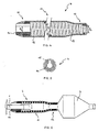
- FIG. 1 to FIG. 3 shows a balloon catheter according to the invention with a tubular catheter shaft 1 having a proximal end (not shown) and has a distal end 2 on which an elongated dilatation balloon 3 is arranged.
- the balloon catheter points proximal to the dilatation balloon 3 a diameter-stable cover sleeve 4, along the catheter shaft 1 steplessly between a proximal limiting element, which in this embodiment is a shoulder 6, and a distal Limiting element is displaceable, which in this case by proximal balloon attachment point 8 of the dilatation balloon 3 am Catheter shaft 1 is formed.
- the distal limiting element 7 can, however also be the folded, deflated dilatation balloon 3 itself.
- device for placing a balloon-expandable stent 9 is the cover sleeve 4 to shorten the fully expandable balloon length partially pushed over the deflated dilatation balloon 3 to the Adjust the balloon length to the length of the stent 9.
- the cover sleeve 4, as shown in FIG. 3 shown be pushed close to their distal end position.
- the cover sleeve 4 Distal from the second section 11, the cover sleeve 4 has a diameter-stable third section 12 with a third inside diameter D 3 , which lies between the first inside diameter D 1 and the second inside diameter D 2 .
- the cover sleeve 4 is not shown in full length; with a total length of the cover sleeve 4 of 20mm, the third section 12 is only about 1mm long.
- the second section 11 and the third section 12 are formed in one piece with a diameter-stable reinforcement 13 consisting of a helically wound wire material in order to be able to withstand the dilation pressure of the covered balloon section.
- the first section 10 is designed as a clamping element 14 and inserted into the second section 11.
- all sections 10, 11 and 12 of the cover sleeve 4 can also be formed in one piece, wherein the reinforcement can be a continuous wire spiral, for example.
- the reinforcement 13 and the tensioning element 14 are covered by an enveloping tube 15 so that the cover sleeve 4 has a smooth, atraumatic outer surface.
- the structure of the inner surface of the enveloping tube 15 represents an embedding for the reinforcement 13, while the tensioning element 14 is spanned distally by turns of the reinforcement 13 and is glued proximally directly into the enveloping tube 15.
- FIG. 5 shows a cross section through the cover sleeve 4 in the region of this adhesive point.
- the tensioning element 14 is designed as a longitudinally slotted tensioning sleeve and enclosed by the cladding tube 15. The slot serves to compensate for diameter tolerances of the catheter shaft 1. If the catheter shaft 1 is dimensionally stable, this slot in the adapter sleeve can be dispensed with.
- the clamping element 14 comprises the catheter shaft 1 proximally of the dilatation balloon 3 so tight that a sufficiently high frictional connection between adapter sleeve and catheter shaft 1 for a secure axial Positioning of the cover sleeve 4 exists.
- the second section 11 and the third sections 12 are pushed over the dilatation balloons 3 in such a way that after inflating the dilatation balloon 3, the diameter-stable third Section 12 proximal to a partially expanded, covered section and distally from the fully expanded, free section of the dilatation balloon 3 is included. This ensures a continuously adjustable balloon length, which according to a selected preset during the use of the Balloon catheter does not change.
Landscapes
- Health & Medical Sciences (AREA)
- Engineering & Computer Science (AREA)
- Biomedical Technology (AREA)
- Heart & Thoracic Surgery (AREA)
- Life Sciences & Earth Sciences (AREA)
- Animal Behavior & Ethology (AREA)
- Veterinary Medicine (AREA)
- Public Health (AREA)
- General Health & Medical Sciences (AREA)
- Transplantation (AREA)
- Vascular Medicine (AREA)
- Oral & Maxillofacial Surgery (AREA)
- Cardiology (AREA)
- Child & Adolescent Psychology (AREA)
- Biophysics (AREA)
- Pulmonology (AREA)
- Anesthesiology (AREA)
- Hematology (AREA)
- Media Introduction/Drainage Providing Device (AREA)
- Materials For Medical Uses (AREA)
Description
- FIG. 1
- eine Seitenansicht des Ballonkatheters, wobei die Abdeckhülse in ihre proximale Endposition geschoben ist, in
- FIG. 2
- eine Seitenansicht der Vorrichtung zum Setzen eines ballonexpandierbaren Stents, wobei die Abdeckhülse des Ballonkatheters einen Teil des Dilatationsballons abdeckt, und in
- FIG. 3
- eine Seitenansicht des Ballonkatheters, dessen Abdeckhülse in eine distale Position geschoben ist, dargestellt ist. In
- FIG. 4
- ist die Abdeckhülse des Ballonkatheters durch einen axialen Längsschnitt und in
- FIG. 5
- durch einen Querschnitt im Bereich der Spannhülse veranschaulicht.
- FIG. 6
- zeigt die Anordnung aus FIG. 3 vergrössert, wobei die Abdeckhülse im Längsschnitt dargestellt ist.
- 1
- Katheterschaft
- 2
- distales Ende
- 3
- Dilatationsballon
- 4
- Abdeckhülse
- 6
- Schulter
- 8
- proximale Befestigungsstelle
- 9
- Stent
- 10
- erster Abschnitt
- 11
- zweiter Abschnitt
- 12
- dritter Abschnitt
- 13
- Armierung
- 14
- Spannelement
- 15
- Hüllschlauch
- D1
- erster Innendurchmesser
- D2
- zweiter Innendurchmesser
- D3
- dritter Innendurchmesser
Claims (15)
- Ballonkatheter mit einem rohrförmigen Katheterschaft (1), der ein proximales und ein distales Ende (2) aufweist, einem länglichen Dilatationsballon (3), der am Katheterschaft (1) in der Nähe des distalen Endes (2) angeordnet ist, und einer längs des Katheterschaftes (1) verschiebbaren, durchmesserstabilen Abdeckhülse (4), die einen den Katheterschaft (1) umfassenden ersten Abschnitt (10) mit einem ersten Innendurchmesser (D1) und einen über den deflatierten Dilatationsballon (3) schiebbaren zweiten Abschnitt (11) mit einem zweiten Innendurchmesser (D2) aufweist, der grösser als der erste Innendurchmesser (D1) ist, dadurch gekennzeichnet, dass die Abdeckhülse (4) am distalen Ende des zweiten Abschnitts (11) einen durchmesserstabilen dritten Abschnitt (12) mit einem dritten Innendurchmesser (D3) aufweist, der zwischen dem ersten Innendurchmesser (D1) und dem zweiten Innendurchmesser (D2) liegt.
- Ballonkatheter nach Anspruch 1,
dadurch gekennzeichnet, dass die Abdeckhülse (4) von proximal auf den deflatierten Dilatationsballon (3) schiebbar ist, wobei der erste Abschnitt (10) proximal und der dritte Abschnitt (12) distal vom zweiten Abschnitt (11) der Abdeckhülse (4) angeordnet ist. - Ballonkatheter nach Anspruch 1 oder 2,
dadurch gekennzeichnet, dass der zweite Abschnitt (11) der Abdeckhülse (4) und einer der anderen Abschnitte (10,12) einstückig ausgebildet sind und der andere übsige Abschnitt (12,10) in den zweiten Abschnitt (11) eingesetzt ist. - Ballonkatheter nach Anspruch 3,
dadurch gekennzeichnet, dass einstückig ausgebildete Abschnitte der Abdeckhülse (4) eine durchmesserstabile, flexible Armierung (13) aufweisen. - Ballonkatheter nach einem der Ansprüche 3 oder 4,
dadurch gekennzeichnet, dass der eingesetzte Abschnitt (10,12) der Abdeckhülse (4) durch ein den Katheterschaft (1) eng umfassendes Spannelement (14) gebildet wird. - Ballonkatheter nach Anspruch 5,
dadurch gekennzeichnet, dass das Spannelement (14) eine längsgeschlitzte Spannhülse ist. - Ballonkatheter nach einem der Ansprüche 4 bis 6,
dadurch gekennzeichnet, dass die Abdeckhülse (4) einen die Armierung (13) und das Spannelement (14) überziehenden Hüllschlauch (15) aufweist. - Ballonkatheter nach Anspruch 2 oder nach einem der Ansprüche 3 bis 7, soweit diese auf Anspruch 2 zurückbezogen sind,
dadurch gekennzeichnet, dass der Katheterschaft (1) ein proximales Begrenzungselement und ein distales Begrenzungselement aufweist, zwischen welchen die Abdeckhülse (4) längs des Katheterschaftes (1) verschiebbar ist. - Ballonkatheter nach Anspruch 8,
dadurch gekennzeichnet, dass das proximale Begrenzungselement eine Schulter (6) am Katheterschaft (1) ist. - Ballonkatheter nach Anspruch 8 oder 9,
dadurch gekennzeichnet, dass das distale Begrenzungselement durch die proximale Befestigungsstelle (8) des Dilatationsballons (3) am Katheterschaft (1) gebildet wird. - Ballonkatheter nach Anspruch 9 oder 10,
dadurch gekennzeichnet, dass das distale Begrenzungselement durch den gefalteten, deflatierten Dilatationsballon (3) gebildet wird. - Ballonkatheter nach einem der Ansprüche 4 bis 11,
dadurch gekennzeichnet, dass die Armierung (13) aus einem schraubenlinienförmig gewickelten Drahtmaterial besteht. - Ballonkatheter nach einem der Ansprüche 4 bis 11,
dadurch gekennzeichnet, dass die Armierung (13) als rohrförmiges Drahtgeflecht ausgebildet ist. - Ballonkatheter nach einem der Ansprüche 4 bis 13,
dadurch gekennzeichnet, dass die Armierung (13) aus einem röntgendichten Material besteht. - Vorrichtung zum Setzen eines ballonexpandierbaren Stents (9), die einen Ballonkatheter nach einem der Ansprüche 1 bis 14 aufweist.
Priority Applications (7)
| Application Number | Priority Date | Filing Date | Title |
|---|---|---|---|
| DE59610631T DE59610631D1 (de) | 1996-11-15 | 1996-11-15 | Ballonkatheter und Vorrichtung zum Setzen eines Stents |
| AT96203188T ATE245952T1 (de) | 1996-11-15 | 1996-11-15 | Ballonkatheter und vorrichtung zum setzen eines stents |
| EP96203188A EP0843990B1 (de) | 1996-11-15 | 1996-11-15 | Ballonkatheter und Vorrichtung zum Setzen eines Stents |
| US08/933,220 US6066155A (en) | 1996-11-15 | 1997-09-18 | Captured sleeve and stent delivery device |
| CA002218406A CA2218406A1 (en) | 1996-11-15 | 1997-10-16 | Balloon catheter and delivery device for a stent |
| JP29084297A JP3419663B2 (ja) | 1996-11-15 | 1997-10-23 | バルーンカテーテル |
| AU45187/97A AU729917B2 (en) | 1996-11-15 | 1997-11-14 | Balloon catheter and delivery device for a stent |
Applications Claiming Priority (1)
| Application Number | Priority Date | Filing Date | Title |
|---|---|---|---|
| EP96203188A EP0843990B1 (de) | 1996-11-15 | 1996-11-15 | Ballonkatheter und Vorrichtung zum Setzen eines Stents |
Publications (2)
| Publication Number | Publication Date |
|---|---|
| EP0843990A1 EP0843990A1 (de) | 1998-05-27 |
| EP0843990B1 true EP0843990B1 (de) | 2003-07-30 |
Family
ID=8224583
Family Applications (1)
| Application Number | Title | Priority Date | Filing Date |
|---|---|---|---|
| EP96203188A Expired - Lifetime EP0843990B1 (de) | 1996-11-15 | 1996-11-15 | Ballonkatheter und Vorrichtung zum Setzen eines Stents |
Country Status (7)
| Country | Link |
|---|---|
| US (1) | US6066155A (de) |
| EP (1) | EP0843990B1 (de) |
| JP (1) | JP3419663B2 (de) |
| AT (1) | ATE245952T1 (de) |
| AU (1) | AU729917B2 (de) |
| CA (1) | CA2218406A1 (de) |
| DE (1) | DE59610631D1 (de) |
Families Citing this family (84)
| Publication number | Priority date | Publication date | Assignee | Title |
|---|---|---|---|---|
| FR2781379B1 (fr) * | 1998-07-22 | 2000-10-06 | Prodimed | Dispositif a ballonnet a diametre nominal ajustable |
| US6168586B1 (en) * | 1998-08-07 | 2001-01-02 | Embol-X, Inc. | Inflatable cannula and method of using same |
| WO2001054761A2 (en) * | 2000-01-28 | 2001-08-02 | William Cook, Europe Aps | Endovascular medical device with plurality of wires |
| US20040082879A1 (en) * | 2000-01-28 | 2004-04-29 | Klint Henrik S. | Endovascular medical device with plurality of wires |
| US8721625B2 (en) * | 2001-01-26 | 2014-05-13 | Cook Medical Technologies Llc | Endovascular medical device with plurality of wires |
| EP1258230A3 (de) | 2001-03-29 | 2003-12-10 | CardioSafe Ltd | Ballonkathetervorrichtung |
| GB0121980D0 (en) | 2001-09-11 | 2001-10-31 | Cathnet Science Holding As | Expandable stent |
| US7351255B2 (en) * | 2001-12-03 | 2008-04-01 | Xtent, Inc. | Stent delivery apparatus and method |
| US7892273B2 (en) | 2001-12-03 | 2011-02-22 | Xtent, Inc. | Custom length stent apparatus |
| US7270668B2 (en) * | 2001-12-03 | 2007-09-18 | Xtent, Inc. | Apparatus and methods for delivering coiled prostheses |
| US20040186551A1 (en) | 2003-01-17 | 2004-09-23 | Xtent, Inc. | Multiple independent nested stent structures and methods for their preparation and deployment |
| US7147656B2 (en) | 2001-12-03 | 2006-12-12 | Xtent, Inc. | Apparatus and methods for delivery of braided prostheses |
| US7182779B2 (en) | 2001-12-03 | 2007-02-27 | Xtent, Inc. | Apparatus and methods for positioning prostheses for deployment from a catheter |
| US7294146B2 (en) * | 2001-12-03 | 2007-11-13 | Xtent, Inc. | Apparatus and methods for delivery of variable length stents |
| US20030135266A1 (en) * | 2001-12-03 | 2003-07-17 | Xtent, Inc. | Apparatus and methods for delivery of multiple distributed stents |
| US7309350B2 (en) * | 2001-12-03 | 2007-12-18 | Xtent, Inc. | Apparatus and methods for deployment of vascular prostheses |
| US8080048B2 (en) | 2001-12-03 | 2011-12-20 | Xtent, Inc. | Stent delivery for bifurcated vessels |
| US7137993B2 (en) | 2001-12-03 | 2006-11-21 | Xtent, Inc. | Apparatus and methods for delivery of multiple distributed stents |
| US7481834B2 (en) * | 2003-04-14 | 2009-01-27 | Tryton Medical, Inc. | Stent for placement at luminal os |
| US8109987B2 (en) * | 2003-04-14 | 2012-02-07 | Tryton Medical, Inc. | Method of treating a lumenal bifurcation |
| US7717953B2 (en) | 2004-10-13 | 2010-05-18 | Tryton Medical, Inc. | Delivery system for placement of prosthesis at luminal OS |
| US7972372B2 (en) * | 2003-04-14 | 2011-07-05 | Tryton Medical, Inc. | Kit for treating vascular bifurcations |
| US8083791B2 (en) * | 2003-04-14 | 2011-12-27 | Tryton Medical, Inc. | Method of treating a lumenal bifurcation |
| US7758630B2 (en) * | 2003-04-14 | 2010-07-20 | Tryton Medical, Inc. | Helical ostium support for treating vascular bifurcations |
| US7731747B2 (en) * | 2003-04-14 | 2010-06-08 | Tryton Medical, Inc. | Vascular bifurcation prosthesis with multiple thin fronds |
| US7241308B2 (en) * | 2003-06-09 | 2007-07-10 | Xtent, Inc. | Stent deployment systems and methods |
| US7604621B2 (en) | 2003-07-30 | 2009-10-20 | Boston Scientific Scimed, Inc. | Bifurcated stent delivery system |
| US20050075711A1 (en) * | 2003-10-03 | 2005-04-07 | Neary Anthony J. | Balloon catheter with selectable diameter and expandable length |
| US7553324B2 (en) * | 2003-10-14 | 2009-06-30 | Xtent, Inc. | Fixed stent delivery devices and methods |
| US7192440B2 (en) * | 2003-10-15 | 2007-03-20 | Xtent, Inc. | Implantable stent delivery devices and methods |
| US7403966B2 (en) * | 2003-12-08 | 2008-07-22 | Freescale Semiconductor, Inc. | Hardware for performing an arithmetic function |
| US7326236B2 (en) | 2003-12-23 | 2008-02-05 | Xtent, Inc. | Devices and methods for controlling and indicating the length of an interventional element |
| US7225518B2 (en) * | 2004-02-23 | 2007-06-05 | Boston Scientific Scimed, Inc. | Apparatus for crimping a stent assembly |
| US7323006B2 (en) | 2004-03-30 | 2008-01-29 | Xtent, Inc. | Rapid exchange interventional devices and methods |
| US7285130B2 (en) | 2004-04-27 | 2007-10-23 | Boston Scientific Scimed, Inc. | Stent delivery system |
| US20050267415A1 (en) * | 2004-05-14 | 2005-12-01 | C. R. Bard, Inc. | Medical devices and methods of use |
| US20050278011A1 (en) | 2004-06-10 | 2005-12-15 | Peckham John E | Stent delivery system |
| US8317859B2 (en) | 2004-06-28 | 2012-11-27 | J.W. Medical Systems Ltd. | Devices and methods for controlling expandable prostheses during deployment |
| US20050288766A1 (en) * | 2004-06-28 | 2005-12-29 | Xtent, Inc. | Devices and methods for controlling expandable prostheses during deployment |
| JP5102023B2 (ja) | 2004-06-29 | 2012-12-19 | シー アール バード インコーポレイテッド | 胃瘻造設チューブとの流体連通を行うための方法およびシステム |
| US7955370B2 (en) * | 2004-08-06 | 2011-06-07 | Boston Scientific Scimed, Inc. | Stent delivery system |
| US7393358B2 (en) * | 2004-08-17 | 2008-07-01 | Boston Scientific Scimed, Inc. | Stent delivery system |
| US20060064064A1 (en) * | 2004-09-17 | 2006-03-23 | Jang G D | Two-step/dual-diameter balloon angioplasty catheter for bifurcation and side-branch vascular anatomy |
| US20080188803A1 (en) * | 2005-02-03 | 2008-08-07 | Jang G David | Triple-profile balloon catheter |
| US7632296B2 (en) * | 2005-03-03 | 2009-12-15 | Boston Scientific Scimed, Inc. | Rolling membrane with hydraulic recapture means for self expanding stent |
| JP2006239219A (ja) * | 2005-03-04 | 2006-09-14 | Olympus Medical Systems Corp | バルーンダイレータ |
| US7402168B2 (en) * | 2005-04-11 | 2008-07-22 | Xtent, Inc. | Custom-length stent delivery system with independently operable expansion elements |
| JP4988725B2 (ja) * | 2005-06-06 | 2012-08-01 | シー・アール・バード・インコーポレーテッド | バルーンチップを含む供給装置および製造方法 |
| US20060282149A1 (en) | 2005-06-08 | 2006-12-14 | Xtent, Inc., A Delaware Corporation | Apparatus and methods for deployment of multiple custom-length prostheses (II) |
| US7938851B2 (en) | 2005-06-08 | 2011-05-10 | Xtent, Inc. | Devices and methods for operating and controlling interventional apparatus |
| US7927362B2 (en) * | 2005-07-21 | 2011-04-19 | Boston Scientific Scimed, Inc. | Laser ablated elastomer sheath profiles to enables stent securement |
| US8038704B2 (en) * | 2005-07-27 | 2011-10-18 | Paul S. Sherburne | Stent and other objects removal from a body |
| US8926679B2 (en) | 2006-03-03 | 2015-01-06 | Boston Scientific Scimed, Inc. | Bifurcated stent system balloon folds |
| WO2007109621A2 (en) | 2006-03-20 | 2007-09-27 | Xtent, Inc. | Apparatus and methods for deployment of linked prosthetic segments |
| WO2007124167A2 (en) * | 2006-04-21 | 2007-11-01 | C. R. Bard, Inc. | Feeding device and bolster apparatus and method for making the same |
| US20070260304A1 (en) * | 2006-05-02 | 2007-11-08 | Daniel Gregorich | Bifurcated stent with minimally circumferentially projected side branch |
| US8439961B2 (en) * | 2006-07-31 | 2013-05-14 | Boston Scientific Scimed, Inc. | Stent retaining mechanisms |
| US20080172120A1 (en) * | 2007-01-12 | 2008-07-17 | Calvin Fenn | Endoprosthesis delivery systems and related methods |
| US20080199510A1 (en) | 2007-02-20 | 2008-08-21 | Xtent, Inc. | Thermo-mechanically controlled implants and methods of use |
| USD567367S1 (en) * | 2007-03-14 | 2008-04-22 | Mongeon Douglas R | Stylet |
| US8486132B2 (en) | 2007-03-22 | 2013-07-16 | J.W. Medical Systems Ltd. | Devices and methods for controlling expandable prostheses during deployment |
| US9101503B2 (en) | 2008-03-06 | 2015-08-11 | J.W. Medical Systems Ltd. | Apparatus having variable strut length and methods of use |
| US8333003B2 (en) | 2008-05-19 | 2012-12-18 | Boston Scientific Scimed, Inc. | Bifurcation stent crimping systems and methods |
| US8828071B2 (en) | 2008-09-25 | 2014-09-09 | Advanced Bifurcation Systems, Inc. | Methods and systems for ostial stenting of a bifurcation |
| US8821562B2 (en) | 2008-09-25 | 2014-09-02 | Advanced Bifurcation Systems, Inc. | Partially crimped stent |
| US11298252B2 (en) | 2008-09-25 | 2022-04-12 | Advanced Bifurcation Systems Inc. | Stent alignment during treatment of a bifurcation |
| US12324756B2 (en) | 2008-09-25 | 2025-06-10 | Advanced Bifurcation Systems Inc. | System and methods for treating a bifurcation |
| CA2739007C (en) | 2008-09-25 | 2017-10-31 | Advanced Bifurcation Systems Inc. | Partially crimped stent |
| US12076258B2 (en) | 2008-09-25 | 2024-09-03 | Advanced Bifurcation Systems Inc. | Selective stent crimping |
| US8382818B2 (en) * | 2009-07-02 | 2013-02-26 | Tryton Medical, Inc. | Ostium support for treating vascular bifurcations |
| WO2011005847A1 (en) | 2009-07-07 | 2011-01-13 | C. R. Bard, Inc. | Extensible internal bolster for a medical device |
| JP2013518697A (ja) * | 2010-02-09 | 2013-05-23 | シー・アール・バード・インコーポレーテッド | 医療装置ボルスターのための収縮指示器 |
| US20110301502A1 (en) * | 2010-02-12 | 2011-12-08 | Sukhjit Gill | In-vessel positioning device |
| CA2794064A1 (en) | 2010-03-24 | 2011-09-29 | Advanced Bifurcation Systems, Inc. | Methods and systems for treating a bifurcation with provisional side branch stenting |
| CN103068345B (zh) | 2010-03-24 | 2015-10-14 | 高级分支系统股份有限公司 | 在对分叉部进行处理过程中的支架对准 |
| CN103037816B (zh) | 2010-03-24 | 2018-12-28 | 高级分支系统股份有限公司 | 用于处理分叉部的系统和方法 |
| KR101022487B1 (ko) * | 2010-05-27 | 2011-03-15 | 변기현 | 사전확장 벌룬 및 스텐트 벌룬이 일체로 구비된 카테터 |
| WO2012054178A1 (en) | 2010-10-21 | 2012-04-26 | Boston Scientific Scimed, Inc. | Stent delivery system with a rolling membrane |
| EP2642946B1 (de) | 2010-11-24 | 2023-08-16 | Poseidon Medical Inc. | Stütze zur behandlung von gefässverzweigungen |
| WO2012109382A2 (en) | 2011-02-08 | 2012-08-16 | Advanced Bifurcation Systems, Inc. | Multi-stent and multi-balloon apparatus for treating bifurcations and methods of use |
| EP2672932B1 (de) | 2011-02-08 | 2018-09-19 | Advanced Bifurcation Systems, Inc. | System zur behandlung einer gabelung mit einem vollständig gecrimpten stent |
| WO2013162724A1 (en) | 2012-04-26 | 2013-10-31 | Tryton Medical, Inc. | Support for treating vascular bifurcations |
| US9526875B2 (en) | 2013-10-31 | 2016-12-27 | Cook Medical Technologies Llc | Adjustable length dilation balloon |
| CN113499175A (zh) * | 2021-07-09 | 2021-10-15 | 柏为(武汉)医疗科技股份有限公司 | 一种球囊扩张导管推进器 |
Family Cites Families (19)
| Publication number | Priority date | Publication date | Assignee | Title |
|---|---|---|---|---|
| US5275622A (en) * | 1983-12-09 | 1994-01-04 | Harrison Medical Technologies, Inc. | Endovascular grafting apparatus, system and method and devices for use therewith |
| US5104399A (en) * | 1986-12-10 | 1992-04-14 | Endovascular Technologies, Inc. | Artificial graft and implantation method |
| US4921479A (en) * | 1987-10-02 | 1990-05-01 | Joseph Grayzel | Catheter sheath with longitudinal seam |
| US5312356A (en) * | 1989-05-22 | 1994-05-17 | Target Therapeutics | Catheter with low-friction distal segment |
| US5049131A (en) * | 1989-05-31 | 1991-09-17 | Ashridge Ag | Balloon catheter |
| DE9010130U1 (de) * | 1989-07-13 | 1990-09-13 | American Medical Systems, Inc., Minnetonka, Minn. | Instrument zum Anbringen eines Aufweitimplantats |
| US5242399A (en) * | 1990-04-25 | 1993-09-07 | Advanced Cardiovascular Systems, Inc. | Method and system for stent delivery |
| US5246421A (en) * | 1992-02-12 | 1993-09-21 | Saab Mark A | Method of treating obstructed regions of bodily passages |
| US5201757A (en) * | 1992-04-03 | 1993-04-13 | Schneider (Usa) Inc. | Medial region deployment of radially self-expanding stents |
| US5509911A (en) * | 1992-11-27 | 1996-04-23 | Maxxim Medical, Inc. | Rotating adapter for a catheterization system |
| WO1994023775A1 (en) * | 1993-03-23 | 1994-10-27 | Abbott Laboratories | Securing collar for cannula connector |
| US5545209A (en) * | 1993-09-30 | 1996-08-13 | Texas Petrodet, Inc. | Controlled deployment of a medical device |
| US5514093A (en) * | 1994-05-19 | 1996-05-07 | Scimed Life Systems, Inc. | Variable length balloon dilatation catheter |
| US5735869A (en) * | 1994-11-30 | 1998-04-07 | Schneider (Europe) A.G. | Balloon catheter and stent delivery device |
| US5628755A (en) * | 1995-02-20 | 1997-05-13 | Schneider (Europe) A.G. | Balloon catheter and stent delivery system |
| US5549551A (en) * | 1994-12-22 | 1996-08-27 | Advanced Cardiovascular Systems, Inc. | Adjustable length balloon catheter |
| ES1030202Y (es) * | 1995-02-20 | 1996-01-16 | Medina Fernandez Aceytuno Alfo | Cateter balon con dispositivo tubular mejorado para el empleo en el tratamiento de estenosis vasculares. |
| US5702417A (en) * | 1995-05-22 | 1997-12-30 | General Surgical Innovations, Inc. | Balloon loaded dissecting instruments |
| US5891154A (en) * | 1997-05-06 | 1999-04-06 | Advanced Cardiovascular System, Inc. | Passive perfusion stent delivery system |
-
1996
- 1996-11-15 AT AT96203188T patent/ATE245952T1/de not_active IP Right Cessation
- 1996-11-15 DE DE59610631T patent/DE59610631D1/de not_active Expired - Fee Related
- 1996-11-15 EP EP96203188A patent/EP0843990B1/de not_active Expired - Lifetime
-
1997
- 1997-09-18 US US08/933,220 patent/US6066155A/en not_active Expired - Lifetime
- 1997-10-16 CA CA002218406A patent/CA2218406A1/en not_active Abandoned
- 1997-10-23 JP JP29084297A patent/JP3419663B2/ja not_active Expired - Fee Related
- 1997-11-14 AU AU45187/97A patent/AU729917B2/en not_active Ceased
Also Published As
| Publication number | Publication date |
|---|---|
| ATE245952T1 (de) | 2003-08-15 |
| AU729917B2 (en) | 2001-02-15 |
| US6066155A (en) | 2000-05-23 |
| CA2218406A1 (en) | 1998-05-15 |
| EP0843990A1 (de) | 1998-05-27 |
| JPH10179752A (ja) | 1998-07-07 |
| DE59610631D1 (de) | 2003-09-04 |
| AU4518797A (en) | 1998-05-21 |
| JP3419663B2 (ja) | 2003-06-23 |
Similar Documents
| Publication | Publication Date | Title |
|---|---|---|
| EP0843990B1 (de) | Ballonkatheter und Vorrichtung zum Setzen eines Stents | |
| DE69921908T2 (de) | Ballonkatheter mit elastischem Füllkörper zum Stützen eines Stents | |
| DE69020075T2 (de) | Katheterführung und Führungsdrahts zur Durchführung eines schnellen Katheteraustausches. | |
| DE60225147T2 (de) | Ballonkatheter und verfahren zu seiner stabilisierung bei der dehnung | |
| DE60026466T2 (de) | Stenteinbringungssystem mit festem Führungsdraht | |
| DE60212048T2 (de) | Katheter mit verbesserter distaler Schubfähigkeit | |
| DE69026010T2 (de) | Schnellaustauschbarer Vasculärkatheter zur Aufrechterhaltung des Zustandes eines Blutgefässes | |
| DE3690224C2 (de) | Gefäßplastische Koronar-Ballon-Sonde | |
| DE69635967T2 (de) | Schnellaustausch-Stentanbringungsballonkatheter | |
| DE60014072T2 (de) | Stentbefestigung durch ballonmodifikation | |
| DE69224379T2 (de) | Perfusionskatheter mit schraubenförmigem ballon für die angioplastie | |
| DE69731560T2 (de) | Stententfaltungskatheter mit zurückschiebbarer hülse | |
| DE69825200T2 (de) | Kathetersystem zum Anbringen eines Stent | |
| DE69426612T2 (de) | Katheter zum Anbringen eines Stents | |
| EP0627201B1 (de) | Vorrichtung zum Freisetzen einer selbstexpandierenden Endoprothese | |
| DE3853057T2 (de) | Entfernbare endoarterielle-Vorrichtung, bestimmt für die Reparatur von Ablösungen in arteriellen Wänden. | |
| DE69304306T2 (de) | Dilatationskatheter | |
| DE3787011T2 (de) | Dilatationskatheter mit dünnem Führungsdraht. | |
| DE60112874T2 (de) | Katheter mit geringem Querschnitt | |
| DE60112573T2 (de) | Verabreichungsanordnung | |
| DE69821543T2 (de) | Ballonkatheter zur Gefässplastik | |
| DE60115239T2 (de) | Vorrichtung zum einbringen eines stents | |
| DE69528385T2 (de) | Vaskulare dilatationsvorrichtung | |
| DE69003042T2 (de) | Katheter. | |
| DE69131805T2 (de) | Leicht auswechselbarer Perfusionskatheter |
Legal Events
| Date | Code | Title | Description |
|---|---|---|---|
| PUAI | Public reference made under article 153(3) epc to a published international application that has entered the european phase |
Free format text: ORIGINAL CODE: 0009012 |
|
| AK | Designated contracting states |
Kind code of ref document: A1 Designated state(s): AT BE CH DE DK ES FR GB IE IT LI NL SE |
|
| 17P | Request for examination filed |
Effective date: 19981127 |
|
| AKX | Designation fees paid |
Free format text: AT BE CH DE DK ES FR GB IE IT LI NL SE |
|
| RBV | Designated contracting states (corrected) |
Designated state(s): AT BE CH DE DK ES FR GB IE IT LI NL SE |
|
| GRAH | Despatch of communication of intention to grant a patent |
Free format text: ORIGINAL CODE: EPIDOS IGRA |
|
| GRAH | Despatch of communication of intention to grant a patent |
Free format text: ORIGINAL CODE: EPIDOS IGRA |
|
| GRAA | (expected) grant |
Free format text: ORIGINAL CODE: 0009210 |
|
| AK | Designated contracting states |
Designated state(s): AT BE CH DE DK ES FR GB IE IT LI NL SE |
|
| REG | Reference to a national code |
Ref country code: GB Ref legal event code: FG4D Free format text: NOT ENGLISH |
|
| REG | Reference to a national code |
Ref country code: CH Ref legal event code: EP |
|
| REG | Reference to a national code |
Ref country code: IE Ref legal event code: FG4D Free format text: GERMAN |
|
| REF | Corresponds to: |
Ref document number: 59610631 Country of ref document: DE Date of ref document: 20030904 Kind code of ref document: P |
|
| PG25 | Lapsed in a contracting state [announced via postgrant information from national office to epo] |
Ref country code: SE Free format text: LAPSE BECAUSE OF FAILURE TO SUBMIT A TRANSLATION OF THE DESCRIPTION OR TO PAY THE FEE WITHIN THE PRESCRIBED TIME-LIMIT Effective date: 20031030 Ref country code: DK Free format text: LAPSE BECAUSE OF FAILURE TO SUBMIT A TRANSLATION OF THE DESCRIPTION OR TO PAY THE FEE WITHIN THE PRESCRIBED TIME-LIMIT Effective date: 20031030 |
|
| PG25 | Lapsed in a contracting state [announced via postgrant information from national office to epo] |
Ref country code: ES Free format text: LAPSE BECAUSE OF FAILURE TO SUBMIT A TRANSLATION OF THE DESCRIPTION OR TO PAY THE FEE WITHIN THE PRESCRIBED TIME-LIMIT Effective date: 20031110 |
|
| PG25 | Lapsed in a contracting state [announced via postgrant information from national office to epo] |
Ref country code: AT Free format text: LAPSE BECAUSE OF NON-PAYMENT OF DUE FEES Effective date: 20031115 |
|
| PG25 | Lapsed in a contracting state [announced via postgrant information from national office to epo] |
Ref country code: LI Free format text: LAPSE BECAUSE OF NON-PAYMENT OF DUE FEES Effective date: 20031130 Ref country code: CH Free format text: LAPSE BECAUSE OF NON-PAYMENT OF DUE FEES Effective date: 20031130 Ref country code: BE Free format text: LAPSE BECAUSE OF NON-PAYMENT OF DUE FEES Effective date: 20031130 |
|
| GBT | Gb: translation of ep patent filed (gb section 77(6)(a)/1977) |
Effective date: 20031117 |
|
| ET | Fr: translation filed | ||
| BERE | Be: lapsed |
Owner name: *SCHNEIDER (EUROPE) G.M.B.H. Effective date: 20031130 |
|
| PLBE | No opposition filed within time limit |
Free format text: ORIGINAL CODE: 0009261 |
|
| STAA | Information on the status of an ep patent application or granted ep patent |
Free format text: STATUS: NO OPPOSITION FILED WITHIN TIME LIMIT |
|
| REG | Reference to a national code |
Ref country code: CH Ref legal event code: PL |
|
| 26N | No opposition filed |
Effective date: 20040504 |
|
| REG | Reference to a national code |
Ref country code: CH Ref legal event code: AUV Free format text: DAS OBGENANNTE PATENT IST, MANGELS BEZAHLUNG DER 8. JAHRESGEBUEHR DURCH VERFUEGUNG VOM 30. JUNI 2004 ZURUECKGEWIESEN WORDEN. DIE VERFUEGUNG KONNTE DEM PATENTBEWERBER NICHT ZUGESTELLT WERDEN. |
|
| PGFP | Annual fee paid to national office [announced via postgrant information from national office to epo] |
Ref country code: GB Payment date: 20051004 Year of fee payment: 10 |
|
| PGFP | Annual fee paid to national office [announced via postgrant information from national office to epo] |
Ref country code: NL Payment date: 20051005 Year of fee payment: 10 |
|
| PGFP | Annual fee paid to national office [announced via postgrant information from national office to epo] |
Ref country code: IE Payment date: 20051026 Year of fee payment: 10 |
|
| PGFP | Annual fee paid to national office [announced via postgrant information from national office to epo] |
Ref country code: FR Payment date: 20051104 Year of fee payment: 10 |
|
| PGFP | Annual fee paid to national office [announced via postgrant information from national office to epo] |
Ref country code: DE Payment date: 20051130 Year of fee payment: 10 |
|
| PG25 | Lapsed in a contracting state [announced via postgrant information from national office to epo] |
Ref country code: IE Free format text: LAPSE BECAUSE OF NON-PAYMENT OF DUE FEES Effective date: 20061115 |
|
| PG25 | Lapsed in a contracting state [announced via postgrant information from national office to epo] |
Ref country code: NL Free format text: LAPSE BECAUSE OF NON-PAYMENT OF DUE FEES Effective date: 20070601 Ref country code: DE Free format text: LAPSE BECAUSE OF NON-PAYMENT OF DUE FEES Effective date: 20070601 |
|
| GBPC | Gb: european patent ceased through non-payment of renewal fee |
Effective date: 20061115 |
|
| NLV4 | Nl: lapsed or anulled due to non-payment of the annual fee |
Effective date: 20070601 |
|
| REG | Reference to a national code |
Ref country code: FR Ref legal event code: ST Effective date: 20070731 |
|
| REG | Reference to a national code |
Ref country code: IE Ref legal event code: MM4A |
|
| PG25 | Lapsed in a contracting state [announced via postgrant information from national office to epo] |
Ref country code: GB Free format text: LAPSE BECAUSE OF NON-PAYMENT OF DUE FEES Effective date: 20061115 |
|
| PGFP | Annual fee paid to national office [announced via postgrant information from national office to epo] |
Ref country code: IT Payment date: 20071120 Year of fee payment: 12 |
|
| PG25 | Lapsed in a contracting state [announced via postgrant information from national office to epo] |
Ref country code: FR Free format text: LAPSE BECAUSE OF NON-PAYMENT OF DUE FEES Effective date: 20061130 |
|
| PG25 | Lapsed in a contracting state [announced via postgrant information from national office to epo] |
Ref country code: IT Free format text: LAPSE BECAUSE OF NON-PAYMENT OF DUE FEES Effective date: 20081115 |