EP0843990B1 - Balloon catheter and delivery device for a stent - Google Patents
Balloon catheter and delivery device for a stent Download PDFInfo
- Publication number
- EP0843990B1 EP0843990B1 EP96203188A EP96203188A EP0843990B1 EP 0843990 B1 EP0843990 B1 EP 0843990B1 EP 96203188 A EP96203188 A EP 96203188A EP 96203188 A EP96203188 A EP 96203188A EP 0843990 B1 EP0843990 B1 EP 0843990B1
- Authority
- EP
- European Patent Office
- Prior art keywords
- balloon
- balloon catheter
- covering sleeve
- catheter according
- catheter shaft
- Prior art date
- Legal status (The legal status is an assumption and is not a legal conclusion. Google has not performed a legal analysis and makes no representation as to the accuracy of the status listed.)
- Expired - Lifetime
Links
Images

Classifications
-
- A—HUMAN NECESSITIES
- A61—MEDICAL OR VETERINARY SCIENCE; HYGIENE
- A61M—DEVICES FOR INTRODUCING MEDIA INTO, OR ONTO, THE BODY; DEVICES FOR TRANSDUCING BODY MEDIA OR FOR TAKING MEDIA FROM THE BODY; DEVICES FOR PRODUCING OR ENDING SLEEP OR STUPOR
- A61M25/00—Catheters; Hollow probes
- A61M25/10—Balloon catheters
-
- A—HUMAN NECESSITIES
- A61—MEDICAL OR VETERINARY SCIENCE; HYGIENE
- A61F—FILTERS IMPLANTABLE INTO BLOOD VESSELS; PROSTHESES; DEVICES PROVIDING PATENCY TO, OR PREVENTING COLLAPSING OF, TUBULAR STRUCTURES OF THE BODY, e.g. STENTS; ORTHOPAEDIC, NURSING OR CONTRACEPTIVE DEVICES; FOMENTATION; TREATMENT OR PROTECTION OF EYES OR EARS; BANDAGES, DRESSINGS OR ABSORBENT PADS; FIRST-AID KITS
- A61F2/00—Filters implantable into blood vessels; Prostheses, i.e. artificial substitutes or replacements for parts of the body; Appliances for connecting them with the body; Devices providing patency to, or preventing collapsing of, tubular structures of the body, e.g. stents
- A61F2/95—Instruments specially adapted for placement or removal of stents or stent-grafts
- A61F2/958—Inflatable balloons for placing stents or stent-grafts
-
- A—HUMAN NECESSITIES
- A61—MEDICAL OR VETERINARY SCIENCE; HYGIENE
- A61M—DEVICES FOR INTRODUCING MEDIA INTO, OR ONTO, THE BODY; DEVICES FOR TRANSDUCING BODY MEDIA OR FOR TAKING MEDIA FROM THE BODY; DEVICES FOR PRODUCING OR ENDING SLEEP OR STUPOR
- A61M25/00—Catheters; Hollow probes
- A61M25/10—Balloon catheters
- A61M2025/1043—Balloon catheters with special features or adapted for special applications
- A61M2025/1068—Balloon catheters with special features or adapted for special applications having means for varying the length or diameter of the deployed balloon, this variations could be caused by excess pressure
-
- A—HUMAN NECESSITIES
- A61—MEDICAL OR VETERINARY SCIENCE; HYGIENE
- A61M—DEVICES FOR INTRODUCING MEDIA INTO, OR ONTO, THE BODY; DEVICES FOR TRANSDUCING BODY MEDIA OR FOR TAKING MEDIA FROM THE BODY; DEVICES FOR PRODUCING OR ENDING SLEEP OR STUPOR
- A61M25/00—Catheters; Hollow probes
- A61M25/10—Balloon catheters
- A61M2025/1043—Balloon catheters with special features or adapted for special applications
- A61M2025/1081—Balloon catheters with special features or adapted for special applications having sheaths or the like for covering the balloon but not forming a permanent part of the balloon, e.g. retractable, dissolvable or tearable sheaths
Definitions
- the invention relates to a balloon catheter with a tubular Catheter shaft, which has a proximal and a distal end, one elongated dilatation balloon located on the catheter shaft near the distal End is arranged, and a slidable along the catheter shaft, diameter-stable cover sleeve, the one the catheter shaft comprehensive first section with a first inner diameter and a with the second section which can be pushed over the deflated dilation balloon has a second inner diameter that is larger than the first Is inside diameter.
- the invention also relates to a device for setting a Balloon expandable stents that have a balloon catheter at the entrance has mentioned type.
- balloon catheter technology the use of balloon catheters is included fixed balloon length known. Many medical applications require that Use of several balloon catheters with different balloon lengths. requires For example, an intervention involving two balloons of different lengths is the case necessary to change the balloon catheter or with a balloon several times to work sequentially. Changing the balloon catheter is very good expensive and sequential work time consuming. Furthermore the risk of injury to the patient is increased or it can increase inadequate dilations.
- a balloon catheter is also a common instrument for the Transport and expansion of a balloon-expandable endoprosthesis, called a stent, which is used to maintain patency of a vessel is set.
- the balloon length is dependent on the length of the stent to select an erroneous expansion of the stent and thereby to avoid associated damage to the vessel. This leads to inevitably to the complex need for a larger selection Balloon catheters with different balloon lengths, around stents to be able to use it correctly and safely.
- EP 0 727 194 A1 shows a balloon catheter at the beginning mentioned type, in which a stable cover sleeve two Can take positions. In its proximal end position, the Cover sleeve the full balloon length for expansion while free in its distal end position covered a proximal balloon section and from prevents expansion up to the nominal diameter of the balloon. This can in such a balloon catheter between two different balloon lengths to be selected.
- the distal end position is frictionally closed Slide the cover sleeve onto a thickening point on the catheter shaft secured.
- the cover sleeve also has a tapered distal end without Reinforcing agent on, however, in use by the under pressure placed dilation balloon is expanded.
- the invention is based on the object of a balloon catheter Specify the type mentioned, in which the balloon length is continuous can be set and a set balloon length when inflating of the dilatation balloon is securely stable.
- a device for placing balloon-expandable stents of different lengths be created that are versatile and easy and safe to use handling.
- the object is achieved according to the invention by a balloon catheter of the type mentioned at the outset with the features of the characterizing part of claim 1 and by a device for setting a Balloon expandable stents according to claim 15.
- this third section is between that of second section covered, partially expandable balloon section and the free, fully expandable balloon section when inflating the Dilatation balloons enclosed stably.
- the cover sleeve is in this Inclusion held in its axial position by the dilation pressure that a stepless adjustment of the balloon length without additional frictional securing means is reached.
- a Balloon catheter according to the invention be it for the dilatation of stenoses or for stent implantation, both as an over-the-wire catheter and as MONORAIL catheter (trademark). In both cases it is in principle possible, the cover sleeve either from proximal or from distal to slide on the deflated dilation balloon and so the free continuously expandable balloon length.
- the cover sleeve is from can be pushed proximally onto the deflated dilatation balloon, the first Section proximal and the third section distal from the second section of the Cover sleeve is arranged.
- the cover sleeve must be inserted the balloon catheter into a blood vessel not through the constriction site are passed through, but it takes after positioning the Dilatation balloons a position proximal to the stenosis.
- the second section the cover sleeve and one of the other sections are integrally formed and the other outer section inserted into the second section what offers manufacturing advantages.
- one-piece sections of the cover sleeve are included a diameter-stable, flexible reinforcement designed to the one hand to be able to withstand high inflation pressures from the dilatation balloon and on the other hand, narrow vascular convolutions when advancing the To be able to adapt balloon catheters in a vascular system.
- the one generated by the tension Friction between the clamping element and the catheter shaft fixes one preset axial position of the cover sleeve on the catheter shaft. This avoids that when inserting the balloon catheter in a patient's body can adjust a set balloon length.
- the Clamping element is preferably a longitudinally slotted clamping sleeve, since one is particularly easy to manufacture. There is a tight fit through the slot the adapter sleeve is guaranteed even with small manufacturing tolerances.
- the Cover sleeve covering the reinforcement and the tensioning element Envelope tube on. This gives the cover sleeve a smooth, atraumatic Outside surface, which the good leadership properties of the Balloon catheters are preserved and the risk of injury to the patient is reduced.
- the catheter shaft has one proximal and one distal Limiting element, between which the cover sleeve along the Catheter shaft is displaceable. This secures the cover sleeve against Slipping off the catheter shaft.
- the proximal delimiter is preferably one shoulder on the catheter shaft and the distal Limiting element is preferred by the proximal attachment point the dilatation balloon on the catheter shaft or through the folded, deflated dilatation balloon itself formed. In the latter case, need for the distal limiting element does not require any special additional measures to be hit.
- the boundary elements represent enlargements of the Shaft diameter through which the cover sleeve due to the Clamping element tightly surrounding the catheter shaft, respectively can be pushed away.
- the reinforcement can consist of a helically wound Wire material exist or be designed as a tubular wire mesh. Both versions are extremely flexible and are pressure-resistant in terms of diameter stability.
- the reinforcement consists of one radiopaque material, so the cover sleeve can Intervention can be made visible on an x-ray screen.
- the essential is also Element of a device for setting balloon-expandable stents created different lengths.
- the advantage of an inventive The device consists in particular in that it is initially, for example for predilating a stenosis with a first balloon length and then for placing a stent with a second balloon length can be used by expanding the device after the Stenosis is then pulled out of the vessel along a guide wire the new balloon length is set by means of the cover sleeve and the too implanting stent in its unexpanded state on the free expandable balloon section is mounted.
- the Balloon catheter passed back to the pre-dilated vascular site re-inflating the dilatation balloon the stent into its expanded Convict state. If necessary, the same balloon catheter can be used and possibly post-dilation with a third balloon length.
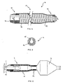
- FIG. 1 to FIG. 3 shows a balloon catheter according to the invention with a tubular catheter shaft 1 having a proximal end (not shown) and has a distal end 2 on which an elongated dilatation balloon 3 is arranged.
- the balloon catheter points proximal to the dilatation balloon 3 a diameter-stable cover sleeve 4, along the catheter shaft 1 steplessly between a proximal limiting element, which in this embodiment is a shoulder 6, and a distal Limiting element is displaceable, which in this case by proximal balloon attachment point 8 of the dilatation balloon 3 am Catheter shaft 1 is formed.
- the distal limiting element 7 can, however also be the folded, deflated dilatation balloon 3 itself.
- device for placing a balloon-expandable stent 9 is the cover sleeve 4 to shorten the fully expandable balloon length partially pushed over the deflated dilatation balloon 3 to the Adjust the balloon length to the length of the stent 9.
- the cover sleeve 4, as shown in FIG. 3 shown be pushed close to their distal end position.
- the cover sleeve 4 Distal from the second section 11, the cover sleeve 4 has a diameter-stable third section 12 with a third inside diameter D 3 , which lies between the first inside diameter D 1 and the second inside diameter D 2 .
- the cover sleeve 4 is not shown in full length; with a total length of the cover sleeve 4 of 20mm, the third section 12 is only about 1mm long.
- the second section 11 and the third section 12 are formed in one piece with a diameter-stable reinforcement 13 consisting of a helically wound wire material in order to be able to withstand the dilation pressure of the covered balloon section.
- the first section 10 is designed as a clamping element 14 and inserted into the second section 11.
- all sections 10, 11 and 12 of the cover sleeve 4 can also be formed in one piece, wherein the reinforcement can be a continuous wire spiral, for example.
- the reinforcement 13 and the tensioning element 14 are covered by an enveloping tube 15 so that the cover sleeve 4 has a smooth, atraumatic outer surface.
- the structure of the inner surface of the enveloping tube 15 represents an embedding for the reinforcement 13, while the tensioning element 14 is spanned distally by turns of the reinforcement 13 and is glued proximally directly into the enveloping tube 15.
- FIG. 5 shows a cross section through the cover sleeve 4 in the region of this adhesive point.
- the tensioning element 14 is designed as a longitudinally slotted tensioning sleeve and enclosed by the cladding tube 15. The slot serves to compensate for diameter tolerances of the catheter shaft 1. If the catheter shaft 1 is dimensionally stable, this slot in the adapter sleeve can be dispensed with.
- the clamping element 14 comprises the catheter shaft 1 proximally of the dilatation balloon 3 so tight that a sufficiently high frictional connection between adapter sleeve and catheter shaft 1 for a secure axial Positioning of the cover sleeve 4 exists.
- the second section 11 and the third sections 12 are pushed over the dilatation balloons 3 in such a way that after inflating the dilatation balloon 3, the diameter-stable third Section 12 proximal to a partially expanded, covered section and distally from the fully expanded, free section of the dilatation balloon 3 is included. This ensures a continuously adjustable balloon length, which according to a selected preset during the use of the Balloon catheter does not change.
Abstract
Description
Die Erfindung bezieht sich auf einen Ballonkatheter mit einem rohrförmigen Katheterschaft, der ein proximales und ein distales Ende aufweist, einem länglichen Dilatationsballon, der am Katheterschaft in der Nähe des distalen Endes angeordnet ist, und einer längs des Katheterschaftes verschiebbaren, durchmesserstabilen Abdeckhülse, die einen den Katheterschaft umfassenden ersten Abschnitt mit einem ersten Innendurchmesser und einen über den deflatierten Dilatationsballon schiebbaren zweiten Abschnitt mit einem zweiten Innendurchmesser aufweist, der grösser als der erste Innendurchmesser ist.The invention relates to a balloon catheter with a tubular Catheter shaft, which has a proximal and a distal end, one elongated dilatation balloon located on the catheter shaft near the distal End is arranged, and a slidable along the catheter shaft, diameter-stable cover sleeve, the one the catheter shaft comprehensive first section with a first inner diameter and a with the second section which can be pushed over the deflated dilation balloon has a second inner diameter that is larger than the first Is inside diameter.
Die Erfindung bezieht sich ausserdem auf eine Vorrichtung zum Setzen eines ballonexpandierbaren Stents, die einen Ballonkatheter der eingangs genannten Art aufweist.The invention also relates to a device for setting a Balloon expandable stents that have a balloon catheter at the entrance has mentioned type.
In der Ballonkathetertechnologie ist die Verwendung von Ballonkathetern mit fester Ballonlänge bekannt. Viele medizinische Anwendungen erfordern den Einsatz mehrerer Ballonkatheter mit unterschiedlichen Ballonlängen. Verlangt ein Eingriff beispielsweise zwei unterschiedlich lange Ballone, so ist es notwendig, den Ballonkatheter zu wechseln oder mit einem Ballon mehrmals aufeinanderfolgend zu arbeiten. Ein Ballonkatheterwechsel ist aber sehr kostspielig und ein sequentielles Arbeiten zeitaufwendig. Darüber hinaus wird das Verletzungsrisiko für den Patienten erhöht oder es kann zu unzureichenden Dilatationen führen.In balloon catheter technology, the use of balloon catheters is included fixed balloon length known. Many medical applications require that Use of several balloon catheters with different balloon lengths. requires For example, an intervention involving two balloons of different lengths is the case necessary to change the balloon catheter or with a balloon several times to work sequentially. Changing the balloon catheter is very good expensive and sequential work time consuming. Furthermore the risk of injury to the patient is increased or it can increase inadequate dilations.
Ein Ballonkatheter ist ausserdem ein gebräuchliches Instrument für den Transport und das Aufweiten einer ballonexpandierbaren Endoprothese, genannt Stent, die zur Aufrechterhaltung der Durchgängigkeit eines Gefässes gesetzt wird. Die Ballonlänge ist dabei in Abhängigkeit der Länge des Stents auszuwählen, um eine fehlerhafte Expansion des Stents und eine damit verbundene Beschädigung des Gefässes zu vermeiden. Dies führt zwangsläufig zum aufwendigen Bedarf einer grösseren Auswahl an Ballonkathetern mit unterschiedlichen Ballonlängen, um Stents vorschriftsmässig und sicher anwenden zu können.A balloon catheter is also a common instrument for the Transport and expansion of a balloon-expandable endoprosthesis, called a stent, which is used to maintain patency of a vessel is set. The balloon length is dependent on the length of the stent to select an erroneous expansion of the stent and thereby to avoid associated damage to the vessel. this leads to inevitably to the complex need for a larger selection Balloon catheters with different balloon lengths, around stents to be able to use it correctly and safely.
Die EP 0 727 194 A1 zeigt dazu einen Ballonkatheter der eingangs erwähnten Art, bei dem eine durchmesserstabile Abdeckhülse zwei Positionen einnehmen kann. In ihrer proximalen Endposition gibt die Abdeckhülse die volle Ballonlänge zur Expansion frei, während sie in ihrer distalen Endposition einen proximalen Ballonabschnitt abgedeckt und von einer Expansion bis zum Nenndurchmesser des Ballons abhält. Dadurch kann bei einem solchen Ballonkatheter zwischen zwei verschiedenen Ballonlängen ausgewählt werden. Die distale Endposition wird reibschlüssig durch Schieben der Abdeckhülse auf eine Verdickungsstelle am Katheterschaft gesichert. Die Abdeckhülse weist auch ein verjüngtes distales Ende ohne Verstärkungsmittel auf, das jedoch im Gebrauch durch den unter Druck gesetzten Dilatationsballon aufgeweitet wird. Der vollexpandierte Teil des Dilatationsballons übt dann eine proximal gerichtete Kraft gegen die Abdeckhülse aus, wodurch diese zu migrieren beginnen kann. Zwischenstellungen der Abdeckhülse und damit Zwischenwerte der Ballonlänge sind bei diesem Katheter nicht wählbar. In diesem Fall wäre die Abdeckhülse nicht in ihrer Lage gesichert und würde unter dem Dilatationsdruck migrieren.EP 0 727 194 A1 shows a balloon catheter at the beginning mentioned type, in which a stable cover sleeve two Can take positions. In its proximal end position, the Cover sleeve the full balloon length for expansion while free in its distal end position covered a proximal balloon section and from prevents expansion up to the nominal diameter of the balloon. This can in such a balloon catheter between two different balloon lengths to be selected. The distal end position is frictionally closed Slide the cover sleeve onto a thickening point on the catheter shaft secured. The cover sleeve also has a tapered distal end without Reinforcing agent on, however, in use by the under pressure placed dilation balloon is expanded. The fully expanded part of the Dilatation balloons then exert a proximal force against the Cover sleeve from which it can begin to migrate. Intermediate positions of the cover sleeve and thus intermediate values of Balloon length cannot be selected with this catheter. In this case it would be Cover sleeve not secured in place and would under the Migrate dilation pressure.
Der Erfindung liegt nun die Aufgabe zugrunde, einen Ballonkatheter der eingangs genannten Art anzugeben, bei dem die Ballonlänge kontinuierlich eingestellt werden kann und eine eingestellte Ballonlänge beim Inflatieren des Dilatationsballons sicher haltbar ist. Darüberhinaus soll eine Vorrichtung zum Setzten ballonexpandierbarer Stents unterschiedlicher Längen geschaffen werden, die vielseitig eingesetzbar sowie einfach und sicher in der Handhabung ist. The invention is based on the object of a balloon catheter Specify the type mentioned, in which the balloon length is continuous can be set and a set balloon length when inflating of the dilatation balloon is securely stable. In addition, a device for placing balloon-expandable stents of different lengths be created that are versatile and easy and safe to use handling.
Die Aufgabe wird gemäss der Erfindung gelöst durch einen Ballonkatheter
der eingangs genannten Art mit den Merkmalen des kennzeichnenden Teils
des Patentanspruchs 1 und durch eine Vorrichtung zum Setzten eines
ballonexpandierbaren Stents nach Patentanspruch 15.The object is achieved according to the invention by a balloon catheter
of the type mentioned at the outset with the features of the characterizing part
of
Wenn die Abdeckhülse am distalen Ende des zweiten Abschnitts einen durchmesserstabilen dritten Abschnitt mit einem dritten Innendurchmesser aufweist, der zwischen dem ersten Innendurchmesser und dem zweiten Innendurchmesser liegt, wird dieser dritte Abschnitt zwischen dem vom zweiten Abschnitt abgedeckten, teilexpandierbaren Ballonabschnitt und dem freien, vollexpandierbaren Ballonabschnitt beim Inflatieren des Dilatationsballons stabil eingeschlossen. Die Abdeckhülse wird in diesem Einschluss durch den Dilatationsdruck in ihrer axialen Position gehalten, so dass ein stufenloses Einstellen der Ballonlänge ohne zusätzliche reibschlüssige Sicherungsmittel erreicht ist. Im praktischen Einsatz kann ein erfindungsgemässer Ballonkatheter, sei es für die Dilatation von Stenosen oder zur Stentimplantation, sowohl als Over-the-wire-Katheter als auch als MONORAIL-Katheter (Trademark) ausgeführt sein. In beiden Fällen ist es prinzipiell möglich, die Abdeckhülse entweder von proximal oder von distal auf den deflatierten Dilatationsballon zu schieben und so die frei expandierbare Ballonlänge kontinuierlich einzustellen.If the cover sleeve at the distal end of the second section diameter-stable third section with a third inner diameter having between the first inner diameter and the second Is inside diameter, this third section is between that of second section covered, partially expandable balloon section and the free, fully expandable balloon section when inflating the Dilatation balloons enclosed stably. The cover sleeve is in this Inclusion held in its axial position by the dilation pressure that a stepless adjustment of the balloon length without additional frictional securing means is reached. In practical use, a Balloon catheter according to the invention, be it for the dilatation of stenoses or for stent implantation, both as an over-the-wire catheter and as MONORAIL catheter (trademark). In both cases it is in principle possible, the cover sleeve either from proximal or from distal to slide on the deflated dilation balloon and so the free continuously expandable balloon length.
In einer bevorzugten Ausführungsform der Erfindung ist die Abdeckhülse von proximal auf den deflatierten Dilatationsballon schiebbar, wobei der erste Abschnitt proximal und der dritte Abschnitt distal vom zweiten Abschnitt der Abdeckhülse angeordnet ist. Dadurch muss die Abdeckhülse beim Einführen des Ballonkatheters in ein Blutgefäss nicht durch die Verengungsstelle hindurchgeführt werden, sondern sie nimmt nach Positionierung des Dilatationsballons eine Stellung proximal von der Stenose ein.In a preferred embodiment of the invention, the cover sleeve is from can be pushed proximally onto the deflated dilatation balloon, the first Section proximal and the third section distal from the second section of the Cover sleeve is arranged. As a result, the cover sleeve must be inserted the balloon catheter into a blood vessel not through the constriction site are passed through, but it takes after positioning the Dilatation balloons a position proximal to the stenosis.
In einer vorteilhaften Ausgestaltung der Erfindung sind der zweite Abschnitt der Abdeckhülse und einer der anderen Abschnitte einstückig ausgebildet und der andere äussere Abschnitt in den zweiten Abschnitt eingesetzt, was fertigungstechnische Vorteile bietet.In an advantageous embodiment of the invention, the second section the cover sleeve and one of the other sections are integrally formed and the other outer section inserted into the second section what offers manufacturing advantages.
Vorzugsweise sind einstückig ausgebildete Abschnitte der Abdeckhülse mit einer durchmesserstabilen, flexiblen Armierung ausgeführt, um einerseits den hohen Inflationsdrücken vom Dilatationsballon standhalten zu können und andererseits sich engen Gefässwindungen beim Vorschieben des Ballonkatheters in einem Gefässsystem anpassen zu können.Preferably, one-piece sections of the cover sleeve are included a diameter-stable, flexible reinforcement designed to the one hand to be able to withstand high inflation pressures from the dilatation balloon and on the other hand, narrow vascular convolutions when advancing the To be able to adapt balloon catheters in a vascular system.
In einer weiteren bevorzugten Ausführungsform der Erfindung wird der eingesetzte Abschnitt der Abdeckhülse durch ein den Katheterschaft eng umfassendes Spannelement gebildet. Der durch die Spannkraft erzeugte Reibschluss zwischen Spannelement und Katheterschaft fixiert eine voreingestellte axiale Position der Abdeckhülse auf dem Katheterschaft. Dadurch wird vermieden, dass sich beim Einführen des Ballonkatheters in den Körper eines Patienten eine eingestellte Ballonlänge verstellen kann. Das Spannelement ist vorzugsweise eine längsgeschlitzte Spannhülse, da eine solche besonders einfach herstellbar ist. Durch den Schlitz ist ein fester Sitz der Spannhülse auch bei kleinen Fertigungstoleranzen gewährleistet.In a further preferred embodiment of the invention, the inserted section of the cover sleeve through a narrow catheter shaft comprehensive clamping element formed. The one generated by the tension Friction between the clamping element and the catheter shaft fixes one preset axial position of the cover sleeve on the catheter shaft. This avoids that when inserting the balloon catheter in a patient's body can adjust a set balloon length. The Clamping element is preferably a longitudinally slotted clamping sleeve, since one is particularly easy to manufacture. There is a tight fit through the slot the adapter sleeve is guaranteed even with small manufacturing tolerances.
In einer anderen vorteilhaften Ausgestaltung der Erfindung weist die Abdeckhülse einen die Armierung und das Spannelement überziehenden Hüllschlauch auf. Dieser verleiht der Abdeckhülse eine glatte, atraumatische Aussenfläche, wodurch die guten Führungseigenschaften des Ballonkatheters erhalten bleiben und das Verletzungsrisiko für den Patienten reduziert wird.In another advantageous embodiment of the invention, the Cover sleeve covering the reinforcement and the tensioning element Envelope tube on. This gives the cover sleeve a smooth, atraumatic Outside surface, which the good leadership properties of the Balloon catheters are preserved and the risk of injury to the patient is reduced.
Der Katheterschaft weist ein proximales und ein distales Begrenzungselement auf, zwischen welchen die Abdeckhülse längs des Katheterschaftes verschiebbar ist. Dies sichert die Abdeckhülse gegen ein Abrutschen vom Katheterschaft. Das proximale Begrenzungselement ist vorzugsweise eine Schulter am Katheterschaft und das distale Begrenzungselement wird bevorzugt durch die proximale Befestigungsstelle des Dilatationsballons am Katheterschaft oder durch den gefalteten, deflatierten Dilatationsballon selbst gebildet. In letzterem Fall brauchen für das distale Begrenzungselement keine besonderen zusätzlichen Massnahmen getroffen werden. Die Begrenzungselemente stellen Vergrösserungen des Schaftdurchmessers dar, über die die Abdeckhülse aufgrund des den Katheterschaft eng umschliessenden Spannelements jeweils nicht hinwegschiebbar ist.The catheter shaft has one proximal and one distal Limiting element, between which the cover sleeve along the Catheter shaft is displaceable. This secures the cover sleeve against Slipping off the catheter shaft. The proximal delimiter is preferably one shoulder on the catheter shaft and the distal Limiting element is preferred by the proximal attachment point the dilatation balloon on the catheter shaft or through the folded, deflated dilatation balloon itself formed. In the latter case, need for the distal limiting element does not require any special additional measures to be hit. The boundary elements represent enlargements of the Shaft diameter through which the cover sleeve due to the Clamping element tightly surrounding the catheter shaft, respectively can be pushed away.
Die Armierung kann aus einem schraubenlinienförmig gewickelten Drahtmaterial bestehen oder als rohrförmiges Drahtgeflecht ausgebildet sein. Beide Ausführungen besitzen eine hohe Flexibilität und sind druckbeständig hinsichtlich der Durchmesserstabilität. Besteht die Armierung aus einem röntgendichten Material, so kann kann die Abdeckhülse während des Eingriffs auf einem Röntgenbildschirm sichtbar gemacht werden.The reinforcement can consist of a helically wound Wire material exist or be designed as a tubular wire mesh. Both versions are extremely flexible and are pressure-resistant in terms of diameter stability. The reinforcement consists of one radiopaque material, so the cover sleeve can Intervention can be made visible on an x-ray screen.
Mit dem oben beschriebenen Ballonkatheter ist auch das wesentliche Element einer Vorrichtung zum Setzen ballonexpandierbarer Stents unterschiedlicher Längen geschaffen. Der Vorteil einer erfindungsgemässen Vorrichtung besteht insbesondere darin, dass sie beispielsweise zunächst zum Vordilatieren einer Stenose mit einer ersten Ballonlänge und anschliessend zum Setzen eines Stents mit einer zweiten Ballonlänge verwendet werden kann, indem die Vorrichtung nach der Aufweitung der Stenose entlang eines Führungsdrahtes aus dem Gefäss gezogen wird, dann mittels der Abdeckhülse die neue Ballonlänge eingestellt wird und der zu implantierende Stent in seinem unexpandierten Zustand auf den frei expandierbaren Ballonabschnitt montiert wird. Anschliessend wird der Ballonkatheter wieder bis zur vordilatierten Gefässstelle geführt, um durch erneutes Inflatieren des Dilatationsballon den Stent in seinen expandierten Zustand zu überführen. Falls erforderlich, kann mit demselben Ballonkatheter und eventuell mit einer dritten Ballonlänge noch eine Nachdilatation erfolgen. With the balloon catheter described above, the essential is also Element of a device for setting balloon-expandable stents created different lengths. The advantage of an inventive The device consists in particular in that it is initially, for example for predilating a stenosis with a first balloon length and then for placing a stent with a second balloon length can be used by expanding the device after the Stenosis is then pulled out of the vessel along a guide wire the new balloon length is set by means of the cover sleeve and the too implanting stent in its unexpanded state on the free expandable balloon section is mounted. Then the Balloon catheter passed back to the pre-dilated vascular site re-inflating the dilatation balloon the stent into its expanded Convict state. If necessary, the same balloon catheter can be used and possibly post-dilation with a third balloon length.
Weitere Vorteile eines erfindungsgemässen Ballonkatheters und einer erfindungsgemässen Vorrichtung zum Setzen eines ballonexpandierbaren Stents ergeben sich aus einem bevorzugten Ausführungsbeispiel, das im folgenden anhand der Zeichnungen näher beschrieben wird, in deren
- FIG. 1
- eine Seitenansicht des Ballonkatheters, wobei die Abdeckhülse in ihre proximale Endposition geschoben ist, in
- FIG. 2
- eine Seitenansicht der Vorrichtung zum Setzen eines ballonexpandierbaren Stents, wobei die Abdeckhülse des Ballonkatheters einen Teil des Dilatationsballons abdeckt, und in
- FIG. 3
- eine Seitenansicht des Ballonkatheters, dessen Abdeckhülse in eine distale Position geschoben ist, dargestellt ist. In
- FIG. 4
- ist die Abdeckhülse des Ballonkatheters durch einen axialen Längsschnitt und in
- FIG. 5
- durch einen Querschnitt im Bereich der Spannhülse veranschaulicht.
- FIG. 6
- zeigt die Anordnung aus FIG. 3 vergrössert, wobei die Abdeckhülse im Längsschnitt dargestellt ist.
- FIG. 1
- a side view of the balloon catheter, wherein the cover sleeve is pushed into its proximal end position, in
- FIG. 2
- a side view of the device for inserting a balloon-expandable stent, wherein the covering sleeve of the balloon catheter covers part of the dilatation balloon, and in
- FIG. 3
- a side view of the balloon catheter, the cover sleeve is pushed into a distal position. In
- FIG. 4
- is the covering sleeve of the balloon catheter through an axial longitudinal section and in
- FIG. 5
- illustrated by a cross section in the area of the clamping sleeve.
- FIG. 6
- shows the arrangement of FIG. 3 enlarged, the cover sleeve being shown in longitudinal section.
FIG. 1 bis FIG. 3 zeigt einen erfindungsgemässen Ballonkatheter mit einem
rohrförmigen Katheterschaft 1, der ein proximales Ende (nicht dargestellt)
und ein distales Ende 2 aufweist, an dem ein länglicher Dilatationsballon 3
angeordnet ist. Proximal vom Dilatationsballon 3 weist der Ballonkatheter
eine durchmesserstabile Abdeckhülse 4 auf, die längs des Katheterschaftes
1 stufenlos zwischen einem proximalen Begrenzungselement , welches in
diesem Ausführungsbeispiel eine Schulter 6 ist, und einem distalen
Begrenzungselement verschiebbar ist, welches in diesem Fall durch die
proximale Ballonbefestigungsstelle 8 des Dilatationsballons 3 am
Katheterschaft 1 gebildet wird. Das distale Begrenzungselement 7 kann aber
auch der gefaltete, deflatierte Dilatationsballon 3 selbst sein. In FIG. 1 ist die
Abdeckhülse 4 in ihre proximale Endposition geschoben dargestellt, so dass
die gesamte Ballonlänge zur Dilatation genutzt werden kann. Bei der in FIG.
2 dargestellten Vorrichtung zum Setzen eines ballonexpandierbaren Stents 9
ist die Abdeckhülse 4 zur Verkürzung der voll expandierbaren Ballonlänge
teilweise über den deflatierten Dilatationsballon 3 geschoben worden, um die
Ballonlänge an die Länge des Stents 9 anzupassen. Zur Einstellung einer
besonders kurzen Ballonlänge kann die Abdeckhülse 4, wie in FIG. 3 gezeigt,
in die Nähe ihrer distalen Endposition geschoben werden. Durch
entsprechendes Verschieben der Abdeckhülse 4 können je nach praktischem
Erfordernis auch andere, nicht in den Figuren dargestellte Ballonlängen
erreicht werden.FIG. 1 to FIG. 3 shows a balloon catheter according to the invention with a
Die Abdeckhülse 4 weist gemäss FIG. 4 proximal einen ersten Abschnitt 10
mit einem ersten Innendurchmesser D1 und einen sich daran anschliessenden
zweiten Abschnitt 11 mit einem zweiten Innendurchmesser D2 auf, der
grösser als der erste Innendurchmesser D1 ist. Distal vom zweiten Abschnitt
11 weist die Abdeckhülse 4 einen durchmesserstabilen dritten Abschnitt 12
mit einem dritten Innendurchmesser D3 auf, der zwischen dem ersten
Innendurchmesser D1 und dem zweiten Innendurchmesser D2 liegt. Der
Übersichtlichkeit halber ist die Abdeckhülse 4 nicht in voller Länge
dargestellt; bei einer Gesamtlänge der Abdeckhülse 4 von 20mm ist der
dritte Abschnitt 12 nur etwa 1mm lang. Der zweite Abschnitt 11 und der
dritte Abschnitt 12 sind einstückig mit einer aus einem
schraubenlinienförmig gewickelten Drahtmaterial bestehende,
durchmesserstabile Armierung 13 ausgebildet, um dem Dilatationsdruck des
abgedeckten Ballonabschnitts standhalten zu können. Der erste Abschnitt 10
ist als Spannelement 14 ausgebildet und in den zweiten Abschnitt 11
eingesetzt. Stattdessen können auch alle Abschnitte 10, 11 und 12 der
Abdeckhülse 4 einstückig ausgebildet sein, wobei die Armierung
beispielsweise eine durchgehende Drahtspirale sein kann. Die Armierung 13
und das Spannelement 14 sind von einem Hüllschlauch 15 überzogen, damit
die Abdeckhülse 4 eine glatte, atraumatische äussere Oberfläche aufweist.
Die Struktur der inneren Oberfläche des Hüllschlauchs 15 stellt eine
Einbettung für die Armierung 13 dar, während das Spannelement 14 distal
von Windungen der Armierung 13 umspannt wird und proximal unmittelbar in
den Hüllschlauch 15 eingeklebt ist. FIG. 5 zeigt einen Querschnitt durch die
Abdeckhülse 4 im Bereich dieser Klebestelle. Das Spannelement 14 ist als
längsgeschlitzte Spannhülse ausgeführt und vom Hüllschlauch 15
eingeschlossen. Der Schlitz dient zum Ausgleich von Durchmessertoleranzen
des Katheterschaftes 1. Bei ausreichender Masshaltigkeit des
Katheterschaftes 1 kann auf diesen Schlitz in der Spannhülse verzichtet
werden.According to FIG. 4 proximally, a
Nach FIG. 6 umfasst das Spannelement 14 den Katheterschaft 1 proximal
vom Dilatationsballon 3 so eng, dass ein genügend hoher Reibschluss
zwischen Spannhülse und Katheterschaft 1 für eine sichere axiale
Positionierung der Abdeckhülse 4 besteht. Der zweite Abschnitt 11 und der
dritte Abschnitt 12 sind derart über den Dilatationsballons 3 geschoben,
dass nach Inflatieren des Dilatationsballons 3 der durchmesserstabile dritte
Abschnitt 12 proximal von einem teilexpandierten, abgedeckten Abschnitt
und distal vom vollexpandierten, freien Abschnitt des Dilatationsballons 3
eingeschlossen ist. Dies sichert eine kontinuierlich einstellbare Ballonlänge,
die sich nach einer gewählten Voreinstellung während des Einsatzes des
Ballonkatheters nicht ändert. According to FIG. 6, the clamping
- 11
- Katheterschaftcatheter shaft
- 22
- distales Endedistal end
- 33
- Dilatationsballondilatation balloon
- 44
- Abdeckhülsecover sleeve
- 66
- Schultershoulder
- 88th
- proximale Befestigungsstelleproximal attachment point
- 99
- Stentstent
- 1010
- erster Abschnittfirst section
- 1111
- zweiter Abschnittsecond part
- 1212
- dritter Abschnittthird section
- 1313
- Armierungreinforcement
- 1414
- Spannelementclamping element
- 1515
- Hüllschlauchbuffer tube
- D1 D 1
- erster Innendurchmesserfirst inner diameter
- D2 D 2
- zweiter Innendurchmessersecond inner diameter
- D3 D 3
- dritter Innendurchmesserthird inner diameter
Claims (15)
- Balloon catheter comprising a tubular catheter shaft (1) having a proximal and a distal end (2), an elongated dilation balloon (3) being arranged on the catheter shaft (1) in the vicinity of the distal end (2) thereof, and an indistensible covering sleeve (4) being movable along the catheter shaft (1), said covering sleeve having a first portion (10) with a first inner diameter (D1) surrounding the catheter shaft (1) and a second portion (11) with a second inner diameter (D2) being pushable over the deflated dilation balloon (3), said second inner diameter being larger than said first inner diameter (D1), characterized in that the covering sleeve (4) comprises an indistensible third portion (12) with a third inner diameter (D3) at the distal end of the second portion (11), said third inner diameter being between said first inner diameter (D1) and said second inner diameter (D2).
- Balloon catheter according to claim 1, characterized in that the covering sleeve (4) is pushable from the proximal end onto the deflated dilation balloon (3), the first portion (10) being arranged proximally and the third portion (12) being arranged distally of the second portion (11) of the covering sleeve (4).
- Balloon catheter according to claim 1 or 2, characterized in that the second portion (11) of the covering sleeve (4) and one of the other portions (10,12) are formed integrally as a single piece and the other remaining portion (12,10) is inserted in the second portion (11).
- Balloon catheter according to claim 3,
characterized in that the portions of the covering sleeve (4) formed integrally as a single piece comprise an indistensible flexible armature (13). - Balloon catheter according to one of claims 3 or 4, characterized in that the inserted portion (10,12) of the covering sleeve (4) is formed by a tension element (14) closely surrounding the catheter shaft (1).
- Balloon catheter according to claim 5, characterized in that the tension element (14) is a longitudinally slotted tensioning husk.
- Balloon catheter according to one of claims 4 to 6, characterized in that the covering sleeve (4) comprises a jacket (15) covering the armature (13) and the tension element (14).
- Balloon catheter according to claim 2 or according to one of claim 3 to 7 when dependent on claim 2, characterized in that the catheter shaft (1) comprises a proximal stop and a distal stop, between which the covering sleeve (4) is movable along the catheter shaft (1).
- Balloon catheter according to claim 8, characterized in that the proximal stop is a shoulder (6) on the catheter shaft (1).
- Balloon catheter according to claim 8 or 9, characterized in that the distal stop is formed by the proximal fixture (8) of the dilation balloon (3) on the catheter shaft (1).
- Balloon catheter according to claim 9 or 10, characterized in that the distal stop is formed by the folded deflated dilation balloon (3).
- Balloon catheter according to one of claims 4 to 11, characterized in that the armature (13) is made of a helically wound wire material.
- Balloon catheter according to one of claims 4 to 11, characterized in that the armature (13) is formed by a tubular wire braiding.
- Balloon catheter according to any one of claims 4 to 13, characterized in that the armature (13) is made of a radiopaque material.
- Delivery device for a balloon expandable stent (9) comprising a balloon catheter according to one of claims 1 to 14.
Priority Applications (7)
| Application Number | Priority Date | Filing Date | Title |
|---|---|---|---|
| DE59610631T DE59610631D1 (en) | 1996-11-15 | 1996-11-15 | Balloon catheter and stent delivery device |
| AT96203188T ATE245952T1 (en) | 1996-11-15 | 1996-11-15 | BALLOON CATHETER AND DEVICE FOR PLACING A STENT |
| EP96203188A EP0843990B1 (en) | 1996-11-15 | 1996-11-15 | Balloon catheter and delivery device for a stent |
| US08/933,220 US6066155A (en) | 1996-11-15 | 1997-09-18 | Captured sleeve and stent delivery device |
| CA002218406A CA2218406A1 (en) | 1996-11-15 | 1997-10-16 | Balloon catheter and delivery device for a stent |
| JP29084297A JP3419663B2 (en) | 1996-11-15 | 1997-10-23 | Balloon catheter |
| AU45187/97A AU729917B2 (en) | 1996-11-15 | 1997-11-14 | Balloon catheter and delivery device for a stent |
Applications Claiming Priority (1)
| Application Number | Priority Date | Filing Date | Title |
|---|---|---|---|
| EP96203188A EP0843990B1 (en) | 1996-11-15 | 1996-11-15 | Balloon catheter and delivery device for a stent |
Publications (2)
| Publication Number | Publication Date |
|---|---|
| EP0843990A1 EP0843990A1 (en) | 1998-05-27 |
| EP0843990B1 true EP0843990B1 (en) | 2003-07-30 |
Family
ID=8224583
Family Applications (1)
| Application Number | Title | Priority Date | Filing Date |
|---|---|---|---|
| EP96203188A Expired - Lifetime EP0843990B1 (en) | 1996-11-15 | 1996-11-15 | Balloon catheter and delivery device for a stent |
Country Status (7)
| Country | Link |
|---|---|
| US (1) | US6066155A (en) |
| EP (1) | EP0843990B1 (en) |
| JP (1) | JP3419663B2 (en) |
| AT (1) | ATE245952T1 (en) |
| AU (1) | AU729917B2 (en) |
| CA (1) | CA2218406A1 (en) |
| DE (1) | DE59610631D1 (en) |
Families Citing this family (80)
| Publication number | Priority date | Publication date | Assignee | Title |
|---|---|---|---|---|
| FR2781379B1 (en) * | 1998-07-22 | 2000-10-06 | Prodimed | BALLOON DEVICE WITH ADJUSTABLE NOMINAL DIAMETER |
| US6168586B1 (en) * | 1998-08-07 | 2001-01-02 | Embol-X, Inc. | Inflatable cannula and method of using same |
| US20040082879A1 (en) * | 2000-01-28 | 2004-04-29 | Klint Henrik S. | Endovascular medical device with plurality of wires |
| WO2001054761A2 (en) * | 2000-01-28 | 2001-08-02 | William Cook, Europe Aps | Endovascular medical device with plurality of wires |
| US8721625B2 (en) * | 2001-01-26 | 2014-05-13 | Cook Medical Technologies Llc | Endovascular medical device with plurality of wires |
| EP1258230A3 (en) | 2001-03-29 | 2003-12-10 | CardioSafe Ltd | Balloon catheter device |
| GB0121980D0 (en) | 2001-09-11 | 2001-10-31 | Cathnet Science Holding As | Expandable stent |
| US7309350B2 (en) * | 2001-12-03 | 2007-12-18 | Xtent, Inc. | Apparatus and methods for deployment of vascular prostheses |
| US7270668B2 (en) * | 2001-12-03 | 2007-09-18 | Xtent, Inc. | Apparatus and methods for delivering coiled prostheses |
| US7137993B2 (en) | 2001-12-03 | 2006-11-21 | Xtent, Inc. | Apparatus and methods for delivery of multiple distributed stents |
| US7147656B2 (en) * | 2001-12-03 | 2006-12-12 | Xtent, Inc. | Apparatus and methods for delivery of braided prostheses |
| US20040186551A1 (en) | 2003-01-17 | 2004-09-23 | Xtent, Inc. | Multiple independent nested stent structures and methods for their preparation and deployment |
| US7294146B2 (en) * | 2001-12-03 | 2007-11-13 | Xtent, Inc. | Apparatus and methods for delivery of variable length stents |
| US20030135266A1 (en) * | 2001-12-03 | 2003-07-17 | Xtent, Inc. | Apparatus and methods for delivery of multiple distributed stents |
| US7182779B2 (en) * | 2001-12-03 | 2007-02-27 | Xtent, Inc. | Apparatus and methods for positioning prostheses for deployment from a catheter |
| US7892273B2 (en) | 2001-12-03 | 2011-02-22 | Xtent, Inc. | Custom length stent apparatus |
| US7351255B2 (en) * | 2001-12-03 | 2008-04-01 | Xtent, Inc. | Stent delivery apparatus and method |
| US8080048B2 (en) | 2001-12-03 | 2011-12-20 | Xtent, Inc. | Stent delivery for bifurcated vessels |
| US7481834B2 (en) * | 2003-04-14 | 2009-01-27 | Tryton Medical, Inc. | Stent for placement at luminal os |
| US7758630B2 (en) * | 2003-04-14 | 2010-07-20 | Tryton Medical, Inc. | Helical ostium support for treating vascular bifurcations |
| US7731747B2 (en) * | 2003-04-14 | 2010-06-08 | Tryton Medical, Inc. | Vascular bifurcation prosthesis with multiple thin fronds |
| US7717953B2 (en) | 2004-10-13 | 2010-05-18 | Tryton Medical, Inc. | Delivery system for placement of prosthesis at luminal OS |
| US8109987B2 (en) | 2003-04-14 | 2012-02-07 | Tryton Medical, Inc. | Method of treating a lumenal bifurcation |
| US8083791B2 (en) * | 2003-04-14 | 2011-12-27 | Tryton Medical, Inc. | Method of treating a lumenal bifurcation |
| US7972372B2 (en) * | 2003-04-14 | 2011-07-05 | Tryton Medical, Inc. | Kit for treating vascular bifurcations |
| US7241308B2 (en) * | 2003-06-09 | 2007-07-10 | Xtent, Inc. | Stent deployment systems and methods |
| US7604621B2 (en) | 2003-07-30 | 2009-10-20 | Boston Scientific Scimed, Inc. | Bifurcated stent delivery system |
| US20050075711A1 (en) * | 2003-10-03 | 2005-04-07 | Neary Anthony J. | Balloon catheter with selectable diameter and expandable length |
| US7553324B2 (en) * | 2003-10-14 | 2009-06-30 | Xtent, Inc. | Fixed stent delivery devices and methods |
| US7192440B2 (en) * | 2003-10-15 | 2007-03-20 | Xtent, Inc. | Implantable stent delivery devices and methods |
| US7403966B2 (en) * | 2003-12-08 | 2008-07-22 | Freescale Semiconductor, Inc. | Hardware for performing an arithmetic function |
| US7326236B2 (en) * | 2003-12-23 | 2008-02-05 | Xtent, Inc. | Devices and methods for controlling and indicating the length of an interventional element |
| US7225518B2 (en) * | 2004-02-23 | 2007-06-05 | Boston Scientific Scimed, Inc. | Apparatus for crimping a stent assembly |
| US7323006B2 (en) | 2004-03-30 | 2008-01-29 | Xtent, Inc. | Rapid exchange interventional devices and methods |
| US7285130B2 (en) * | 2004-04-27 | 2007-10-23 | Boston Scientific Scimed, Inc. | Stent delivery system |
| US20050267415A1 (en) * | 2004-05-14 | 2005-12-01 | C. R. Bard, Inc. | Medical devices and methods of use |
| US20050278011A1 (en) * | 2004-06-10 | 2005-12-15 | Peckham John E | Stent delivery system |
| US20050288766A1 (en) | 2004-06-28 | 2005-12-29 | Xtent, Inc. | Devices and methods for controlling expandable prostheses during deployment |
| US8317859B2 (en) | 2004-06-28 | 2012-11-27 | J.W. Medical Systems Ltd. | Devices and methods for controlling expandable prostheses during deployment |
| JP5102023B2 (en) | 2004-06-29 | 2012-12-19 | シー アール バード インコーポレイテッド | Method and system for fluid communication with a gastrostomy tube |
| US7955370B2 (en) * | 2004-08-06 | 2011-06-07 | Boston Scientific Scimed, Inc. | Stent delivery system |
| US7393358B2 (en) * | 2004-08-17 | 2008-07-01 | Boston Scientific Scimed, Inc. | Stent delivery system |
| US20060064064A1 (en) * | 2004-09-17 | 2006-03-23 | Jang G D | Two-step/dual-diameter balloon angioplasty catheter for bifurcation and side-branch vascular anatomy |
| US20080188803A1 (en) * | 2005-02-03 | 2008-08-07 | Jang G David | Triple-profile balloon catheter |
| US7632296B2 (en) * | 2005-03-03 | 2009-12-15 | Boston Scientific Scimed, Inc. | Rolling membrane with hydraulic recapture means for self expanding stent |
| JP2006239219A (en) * | 2005-03-04 | 2006-09-14 | Olympus Medical Systems Corp | Balloon dilator |
| US7402168B2 (en) * | 2005-04-11 | 2008-07-22 | Xtent, Inc. | Custom-length stent delivery system with independently operable expansion elements |
| JP4988725B2 (en) * | 2005-06-06 | 2012-08-01 | シー・アール・バード・インコーポレーテッド | Supply device including balloon tip and manufacturing method |
| US7938851B2 (en) | 2005-06-08 | 2011-05-10 | Xtent, Inc. | Devices and methods for operating and controlling interventional apparatus |
| US7320702B2 (en) | 2005-06-08 | 2008-01-22 | Xtent, Inc. | Apparatus and methods for deployment of multiple custom-length prostheses (III) |
| US7927362B2 (en) * | 2005-07-21 | 2011-04-19 | Boston Scientific Scimed, Inc. | Laser ablated elastomer sheath profiles to enables stent securement |
| US8038704B2 (en) * | 2005-07-27 | 2011-10-18 | Paul S. Sherburne | Stent and other objects removal from a body |
| US8926679B2 (en) | 2006-03-03 | 2015-01-06 | Boston Scientific Scimed, Inc. | Bifurcated stent system balloon folds |
| WO2007109621A2 (en) | 2006-03-20 | 2007-09-27 | Xtent, Inc. | Apparatus and methods for deployment of linked prosthetic segments |
| US8551043B2 (en) * | 2006-04-21 | 2013-10-08 | C. R. Bard, Inc. | Feeding device and bolster apparatus and method for making the same |
| US20070260304A1 (en) * | 2006-05-02 | 2007-11-08 | Daniel Gregorich | Bifurcated stent with minimally circumferentially projected side branch |
| US8439961B2 (en) * | 2006-07-31 | 2013-05-14 | Boston Scientific Scimed, Inc. | Stent retaining mechanisms |
| US20080172120A1 (en) * | 2007-01-12 | 2008-07-17 | Calvin Fenn | Endoprosthesis delivery systems and related methods |
| US20080199510A1 (en) | 2007-02-20 | 2008-08-21 | Xtent, Inc. | Thermo-mechanically controlled implants and methods of use |
| US8486132B2 (en) | 2007-03-22 | 2013-07-16 | J.W. Medical Systems Ltd. | Devices and methods for controlling expandable prostheses during deployment |
| US9101503B2 (en) | 2008-03-06 | 2015-08-11 | J.W. Medical Systems Ltd. | Apparatus having variable strut length and methods of use |
| US8333003B2 (en) | 2008-05-19 | 2012-12-18 | Boston Scientific Scimed, Inc. | Bifurcation stent crimping systems and methods |
| US8821562B2 (en) | 2008-09-25 | 2014-09-02 | Advanced Bifurcation Systems, Inc. | Partially crimped stent |
| US8769796B2 (en) | 2008-09-25 | 2014-07-08 | Advanced Bifurcation Systems, Inc. | Selective stent crimping |
| US11298252B2 (en) | 2008-09-25 | 2022-04-12 | Advanced Bifurcation Systems Inc. | Stent alignment during treatment of a bifurcation |
| CN102215780B (en) | 2008-09-25 | 2015-10-14 | 高级分支系统股份有限公司 | Part crimped stent |
| US8382818B2 (en) * | 2009-07-02 | 2013-02-26 | Tryton Medical, Inc. | Ostium support for treating vascular bifurcations |
| WO2011005847A1 (en) | 2009-07-07 | 2011-01-13 | C. R. Bard, Inc. | Extensible internal bolster for a medical device |
| MX2012009112A (en) * | 2010-02-09 | 2013-02-27 | Bard Inc C R | Deflation indicator for a medical device bolster. |
| US20110301502A1 (en) * | 2010-02-12 | 2011-12-08 | Sukhjit Gill | In-vessel positioning device |
| CN103037816B (en) | 2010-03-24 | 2018-12-28 | 高级分支系统股份有限公司 | System and method for handling furcation |
| AU2011232360B2 (en) | 2010-03-24 | 2015-10-08 | Advanced Bifurcation Systems Inc. | Methods and systems for treating a bifurcation with provisional side branch stenting |
| WO2011119883A1 (en) | 2010-03-24 | 2011-09-29 | Advanced Bifurcation Systems, Inc. | Stent alignment during treatment of a bifurcation |
| KR101022487B1 (en) * | 2010-05-27 | 2011-03-15 | 변기현 | Predilation balloon-stent combined catheter |
| US9931232B2 (en) | 2010-10-21 | 2018-04-03 | Boston Scientific Scimed, Inc. | Stent delivery system |
| US9707108B2 (en) | 2010-11-24 | 2017-07-18 | Tryton Medical, Inc. | Support for treating vascular bifurcations |
| EP2672932B1 (en) | 2011-02-08 | 2018-09-19 | Advanced Bifurcation Systems, Inc. | System for treating a bifurcation with a fully crimped stent |
| WO2012109382A2 (en) | 2011-02-08 | 2012-08-16 | Advanced Bifurcation Systems, Inc. | Multi-stent and multi-balloon apparatus for treating bifurcations and methods of use |
| WO2013162724A1 (en) | 2012-04-26 | 2013-10-31 | Tryton Medical, Inc. | Support for treating vascular bifurcations |
| US9526875B2 (en) | 2013-10-31 | 2016-12-27 | Cook Medical Technologies Llc | Adjustable length dilation balloon |
Family Cites Families (19)
| Publication number | Priority date | Publication date | Assignee | Title |
|---|---|---|---|---|
| US5275622A (en) * | 1983-12-09 | 1994-01-04 | Harrison Medical Technologies, Inc. | Endovascular grafting apparatus, system and method and devices for use therewith |
| US5104399A (en) * | 1986-12-10 | 1992-04-14 | Endovascular Technologies, Inc. | Artificial graft and implantation method |
| US4921479A (en) * | 1987-10-02 | 1990-05-01 | Joseph Grayzel | Catheter sheath with longitudinal seam |
| US5312356A (en) * | 1989-05-22 | 1994-05-17 | Target Therapeutics | Catheter with low-friction distal segment |
| US5049131A (en) * | 1989-05-31 | 1991-09-17 | Ashridge Ag | Balloon catheter |
| EP0408245B1 (en) * | 1989-07-13 | 1994-03-02 | American Medical Systems, Inc. | Stent placement instrument |
| US5242399A (en) * | 1990-04-25 | 1993-09-07 | Advanced Cardiovascular Systems, Inc. | Method and system for stent delivery |
| US5246421A (en) * | 1992-02-12 | 1993-09-21 | Saab Mark A | Method of treating obstructed regions of bodily passages |
| US5201757A (en) * | 1992-04-03 | 1993-04-13 | Schneider (Usa) Inc. | Medial region deployment of radially self-expanding stents |
| US5509911A (en) * | 1992-11-27 | 1996-04-23 | Maxxim Medical, Inc. | Rotating adapter for a catheterization system |
| WO1994023775A1 (en) * | 1993-03-23 | 1994-10-27 | Abbott Laboratories | Securing collar for cannula connector |
| US5545209A (en) * | 1993-09-30 | 1996-08-13 | Texas Petrodet, Inc. | Controlled deployment of a medical device |
| US5514093A (en) * | 1994-05-19 | 1996-05-07 | Scimed Life Systems, Inc. | Variable length balloon dilatation catheter |
| US5628755A (en) * | 1995-02-20 | 1997-05-13 | Schneider (Europe) A.G. | Balloon catheter and stent delivery system |
| US5735869A (en) * | 1994-11-30 | 1998-04-07 | Schneider (Europe) A.G. | Balloon catheter and stent delivery device |
| US5549551A (en) * | 1994-12-22 | 1996-08-27 | Advanced Cardiovascular Systems, Inc. | Adjustable length balloon catheter |
| ES1030202Y (en) * | 1995-02-20 | 1996-01-16 | Medina Fernandez Aceytuno Alfo | BALL CATHETER WITH IMPROVED TUBULAR DEVICE FOR USE IN THE TREATMENT OF VASCULAR STENOSIS. |
| US5702417A (en) * | 1995-05-22 | 1997-12-30 | General Surgical Innovations, Inc. | Balloon loaded dissecting instruments |
| US5891154A (en) * | 1997-05-06 | 1999-04-06 | Advanced Cardiovascular System, Inc. | Passive perfusion stent delivery system |
-
1996
- 1996-11-15 EP EP96203188A patent/EP0843990B1/en not_active Expired - Lifetime
- 1996-11-15 AT AT96203188T patent/ATE245952T1/en not_active IP Right Cessation
- 1996-11-15 DE DE59610631T patent/DE59610631D1/en not_active Expired - Fee Related
-
1997
- 1997-09-18 US US08/933,220 patent/US6066155A/en not_active Expired - Lifetime
- 1997-10-16 CA CA002218406A patent/CA2218406A1/en not_active Abandoned
- 1997-10-23 JP JP29084297A patent/JP3419663B2/en not_active Expired - Fee Related
- 1997-11-14 AU AU45187/97A patent/AU729917B2/en not_active Ceased
Also Published As
| Publication number | Publication date |
|---|---|
| CA2218406A1 (en) | 1998-05-15 |
| DE59610631D1 (en) | 2003-09-04 |
| JPH10179752A (en) | 1998-07-07 |
| JP3419663B2 (en) | 2003-06-23 |
| US6066155A (en) | 2000-05-23 |
| AU729917B2 (en) | 2001-02-15 |
| ATE245952T1 (en) | 2003-08-15 |
| EP0843990A1 (en) | 1998-05-27 |
| AU4518797A (en) | 1998-05-21 |
Similar Documents
| Publication | Publication Date | Title |
|---|---|---|
| EP0843990B1 (en) | Balloon catheter and delivery device for a stent | |
| DE69921908T2 (en) | Balloon catheter with elastic filling for supporting a stent | |
| DE60225147T2 (en) | BALLOON CATHETER AND METHOD FOR STABILIZING THE STRENGTH | |
| DE60026466T2 (en) | Stent delivery system with fixed guidewire | |
| DE60212048T2 (en) | Catheter with improved distal pushing ability | |
| DE3690224C2 (en) | Vascular plastic coronary balloon probe | |
| DE69635967T2 (en) | Rapid exchange stent delivery balloon catheter | |
| DE60014072T2 (en) | STENT ATTACHMENT BY BALLOON MODIFICATION | |
| DE60032056T2 (en) | Catheter for attaching a primary stent | |
| DE69731560T2 (en) | STENT DISAPPEARANCE CATHETER WITH RETRACTABLE SLEEVE | |
| DE69825200T2 (en) | Catheter system for stent delivery | |
| EP0627201B1 (en) | Device for releasing a self-expanding endoprosthesis | |
| DE60112573T2 (en) | ADMINISTRATION ARRANGEMENT | |
| DE60112874T2 (en) | Low profile catheter | |
| DE69821543T2 (en) | Balloon catheter for vascular plastic | |
| DE60115239T2 (en) | DEVICE FOR INTRODUCING A STENT | |
| DE60034918T2 (en) | Fast replacement catheter for self-expanding stent | |
| EP1200018B1 (en) | Insertion catheter for vascular prostheses | |
| EP0479730B1 (en) | Balloon dilatation catheter | |
| DE60030953T2 (en) | GUIDING WIRE-SUPPRESSED BALLOON CATHETER | |
| DE60214973T2 (en) | DEVICE FOR IMPLANTING A STENT WITH LIQUID DISPENSER | |
| DE69729633T2 (en) | IMPLANTABLE DEVICE FOR SUSTAINING OR RESTORING A NORMAL BODY VESSEL CROSS SECTION | |
| DE60021173T2 (en) | BIFURKATIONSSTENTEINFÜHRSYSTEM | |
| DE69924100T2 (en) | DEVICE FOR REVERSIBLE INSERTION OF AN ENDOPROTHESIS | |
| DE102005052226B4 (en) | Stent for insertion into human body cavities, especially in blood vessels |
Legal Events
| Date | Code | Title | Description |
|---|---|---|---|
| PUAI | Public reference made under article 153(3) epc to a published international application that has entered the european phase |
Free format text: ORIGINAL CODE: 0009012 |
|
| AK | Designated contracting states |
Kind code of ref document: A1 Designated state(s): AT BE CH DE DK ES FR GB IE IT LI NL SE |
|
| 17P | Request for examination filed |
Effective date: 19981127 |
|
| AKX | Designation fees paid |
Free format text: AT BE CH DE DK ES FR GB IE IT LI NL SE |
|
| RBV | Designated contracting states (corrected) |
Designated state(s): AT BE CH DE DK ES FR GB IE IT LI NL SE |
|
| GRAH | Despatch of communication of intention to grant a patent |
Free format text: ORIGINAL CODE: EPIDOS IGRA |
|
| GRAH | Despatch of communication of intention to grant a patent |
Free format text: ORIGINAL CODE: EPIDOS IGRA |
|
| GRAA | (expected) grant |
Free format text: ORIGINAL CODE: 0009210 |
|
| AK | Designated contracting states |
Designated state(s): AT BE CH DE DK ES FR GB IE IT LI NL SE |
|
| REG | Reference to a national code |
Ref country code: GB Ref legal event code: FG4D Free format text: NOT ENGLISH |
|
| REG | Reference to a national code |
Ref country code: CH Ref legal event code: EP |
|
| REG | Reference to a national code |
Ref country code: IE Ref legal event code: FG4D Free format text: GERMAN |
|
| REF | Corresponds to: |
Ref document number: 59610631 Country of ref document: DE Date of ref document: 20030904 Kind code of ref document: P |
|
| PG25 | Lapsed in a contracting state [announced via postgrant information from national office to epo] |
Ref country code: SE Free format text: LAPSE BECAUSE OF FAILURE TO SUBMIT A TRANSLATION OF THE DESCRIPTION OR TO PAY THE FEE WITHIN THE PRESCRIBED TIME-LIMIT Effective date: 20031030 Ref country code: DK Free format text: LAPSE BECAUSE OF FAILURE TO SUBMIT A TRANSLATION OF THE DESCRIPTION OR TO PAY THE FEE WITHIN THE PRESCRIBED TIME-LIMIT Effective date: 20031030 |
|
| PG25 | Lapsed in a contracting state [announced via postgrant information from national office to epo] |
Ref country code: ES Free format text: LAPSE BECAUSE OF FAILURE TO SUBMIT A TRANSLATION OF THE DESCRIPTION OR TO PAY THE FEE WITHIN THE PRESCRIBED TIME-LIMIT Effective date: 20031110 |
|
| PG25 | Lapsed in a contracting state [announced via postgrant information from national office to epo] |
Ref country code: AT Free format text: LAPSE BECAUSE OF NON-PAYMENT OF DUE FEES Effective date: 20031115 |
|
| PG25 | Lapsed in a contracting state [announced via postgrant information from national office to epo] |
Ref country code: LI Free format text: LAPSE BECAUSE OF NON-PAYMENT OF DUE FEES Effective date: 20031130 Ref country code: CH Free format text: LAPSE BECAUSE OF NON-PAYMENT OF DUE FEES Effective date: 20031130 Ref country code: BE Free format text: LAPSE BECAUSE OF NON-PAYMENT OF DUE FEES Effective date: 20031130 |
|
| GBT | Gb: translation of ep patent filed (gb section 77(6)(a)/1977) |
Effective date: 20031117 |
|
| ET | Fr: translation filed | ||
| BERE | Be: lapsed |
Owner name: *SCHNEIDER (EUROPE) G.M.B.H. Effective date: 20031130 |
|
| PLBE | No opposition filed within time limit |
Free format text: ORIGINAL CODE: 0009261 |
|
| STAA | Information on the status of an ep patent application or granted ep patent |
Free format text: STATUS: NO OPPOSITION FILED WITHIN TIME LIMIT |
|
| REG | Reference to a national code |
Ref country code: CH Ref legal event code: PL |
|
| 26N | No opposition filed |
Effective date: 20040504 |
|
| REG | Reference to a national code |
Ref country code: CH Ref legal event code: AUV Free format text: DAS OBGENANNTE PATENT IST, MANGELS BEZAHLUNG DER 8. JAHRESGEBUEHR DURCH VERFUEGUNG VOM 30. JUNI 2004 ZURUECKGEWIESEN WORDEN. DIE VERFUEGUNG KONNTE DEM PATENTBEWERBER NICHT ZUGESTELLT WERDEN. |
|
| PGFP | Annual fee paid to national office [announced via postgrant information from national office to epo] |
Ref country code: GB Payment date: 20051004 Year of fee payment: 10 |
|
| PGFP | Annual fee paid to national office [announced via postgrant information from national office to epo] |
Ref country code: NL Payment date: 20051005 Year of fee payment: 10 |
|
| PGFP | Annual fee paid to national office [announced via postgrant information from national office to epo] |
Ref country code: IE Payment date: 20051026 Year of fee payment: 10 |
|
| PGFP | Annual fee paid to national office [announced via postgrant information from national office to epo] |
Ref country code: FR Payment date: 20051104 Year of fee payment: 10 |
|
| PGFP | Annual fee paid to national office [announced via postgrant information from national office to epo] |
Ref country code: DE Payment date: 20051130 Year of fee payment: 10 |
|
| PG25 | Lapsed in a contracting state [announced via postgrant information from national office to epo] |
Ref country code: IE Free format text: LAPSE BECAUSE OF NON-PAYMENT OF DUE FEES Effective date: 20061115 |
|
| PG25 | Lapsed in a contracting state [announced via postgrant information from national office to epo] |
Ref country code: NL Free format text: LAPSE BECAUSE OF NON-PAYMENT OF DUE FEES Effective date: 20070601 Ref country code: DE Free format text: LAPSE BECAUSE OF NON-PAYMENT OF DUE FEES Effective date: 20070601 |
|
| GBPC | Gb: european patent ceased through non-payment of renewal fee |
Effective date: 20061115 |
|
| NLV4 | Nl: lapsed or anulled due to non-payment of the annual fee |
Effective date: 20070601 |
|
| REG | Reference to a national code |
Ref country code: FR Ref legal event code: ST Effective date: 20070731 |
|
| REG | Reference to a national code |
Ref country code: IE Ref legal event code: MM4A |
|
| PG25 | Lapsed in a contracting state [announced via postgrant information from national office to epo] |
Ref country code: GB Free format text: LAPSE BECAUSE OF NON-PAYMENT OF DUE FEES Effective date: 20061115 |
|
| PGFP | Annual fee paid to national office [announced via postgrant information from national office to epo] |
Ref country code: IT Payment date: 20071120 Year of fee payment: 12 |
|
| PG25 | Lapsed in a contracting state [announced via postgrant information from national office to epo] |
Ref country code: FR Free format text: LAPSE BECAUSE OF NON-PAYMENT OF DUE FEES Effective date: 20061130 |
|
| PG25 | Lapsed in a contracting state [announced via postgrant information from national office to epo] |
Ref country code: IT Free format text: LAPSE BECAUSE OF NON-PAYMENT OF DUE FEES Effective date: 20081115 |