EP0843274A2 - Kartenleser - Google Patents
Kartenleser Download PDFInfo
- Publication number
- EP0843274A2 EP0843274A2 EP97402756A EP97402756A EP0843274A2 EP 0843274 A2 EP0843274 A2 EP 0843274A2 EP 97402756 A EP97402756 A EP 97402756A EP 97402756 A EP97402756 A EP 97402756A EP 0843274 A2 EP0843274 A2 EP 0843274A2
- Authority
- EP
- European Patent Office
- Prior art keywords
- card
- magnetic
- contact
- magnetic head
- driving path
- Prior art date
- Legal status (The legal status is an assumption and is not a legal conclusion. Google has not performed a legal analysis and makes no representation as to the accuracy of the status listed.)
- Withdrawn
Links
Images


Classifications
-
- G—PHYSICS
- G06—COMPUTING; CALCULATING OR COUNTING
- G06K—GRAPHICAL DATA READING; PRESENTATION OF DATA; RECORD CARRIERS; HANDLING RECORD CARRIERS
- G06K7/00—Methods or arrangements for sensing record carriers, e.g. for reading patterns
- G06K7/0013—Methods or arrangements for sensing record carriers, e.g. for reading patterns by galvanic contacts, e.g. card connectors for ISO-7816 compliant smart cards or memory cards, e.g. SD card readers
- G06K7/0021—Methods or arrangements for sensing record carriers, e.g. for reading patterns by galvanic contacts, e.g. card connectors for ISO-7816 compliant smart cards or memory cards, e.g. SD card readers for reading/sensing record carriers having surface contacts
- G06K7/003—Methods or arrangements for sensing record carriers, e.g. for reading patterns by galvanic contacts, e.g. card connectors for ISO-7816 compliant smart cards or memory cards, e.g. SD card readers for reading/sensing record carriers having surface contacts means for pressing the connector contacts in the direction of the card contacts to assure trustworthy electrical connection between card and connector
-
- G—PHYSICS
- G06—COMPUTING; CALCULATING OR COUNTING
- G06K—GRAPHICAL DATA READING; PRESENTATION OF DATA; RECORD CARRIERS; HANDLING RECORD CARRIERS
- G06K13/00—Conveying record carriers from one station to another, e.g. from stack to punching mechanism
- G06K13/02—Conveying record carriers from one station to another, e.g. from stack to punching mechanism the record carrier having longitudinal dimension comparable with transverse dimension, e.g. punched card
- G06K13/08—Feeding or discharging cards
-
- G—PHYSICS
- G06—COMPUTING; CALCULATING OR COUNTING
- G06K—GRAPHICAL DATA READING; PRESENTATION OF DATA; RECORD CARRIERS; HANDLING RECORD CARRIERS
- G06K7/00—Methods or arrangements for sensing record carriers, e.g. for reading patterns
- G06K7/0004—Hybrid readers
Definitions
- the present invention relates to a card reader which handles a magnetic card or an IC card and the like.
- an IC or magnetic card on which data are stored is held in the thickness direction by a pair of rollers, at least one of which is driven by a motor and the like, thereby transferring the card to the driving path.
- a magnetic card reader which is disclosed in Japanese Patent Laid Open No. H5-12498, for example, a magnetic card is held by three pairs of rollers arranged in the driving direction thereby transferring the magnetic card.
- a magnetic strip formed on the magnetic card is moved with respect to the magnetic head.
- the size of a card insertion slot is somewhat larger than the card, therefore, the card is not always inserted straight.
- the distance by which the card is transferred is set long such that the magnetic card which is inserted at a slanted angle or in an askew manner is straightened before it reaches the magnetic head.
- providing a long path is undesirable as it prevents the production of reduced-size card readers.
- one or both sides of the card normally is formed with a magnetic strip.
- the magnetic information on the magnetic strip is recorded /reproduced by the magnetic heads formed opposite each other across the card driving path.
- each of the magnetic heads are designed to be pressed by a compression coil spring such that the magnetic heads are projected to transfer the force to a magnetic card.
- the magnetic head deviates from the base position due to the warping of the card. Upon removal of the card, the head deviation is maintained. If a magnetic card is inserted into a slot while the magnetic head is deviated from its original position, the end of the card contacts a side of the magnetic head, thereby affecting the smooth driving of the card.
- current card readers may be used to read both magnetic cards and IC cards.
- the IC terminal formed on one side of the card is contacted by the card reader, and the IC contact block of the card reader is moved by means of a specific actuator (solenoid).
- a mechanism, independent from the driving mechanism for transferring the IC card, to drive the IC contact block is required, thus increasing the number of components, cost and size of the card reader.
- the IC contact block is designed to be lowered along with the card movement, the load during the IC card transfer increases, thus causing the card to jam.
- a card reader may be designed such that the magnetic head is given the capability to record/reproduce magnetic data, and if the IC contact block is lowered during such recording reproducing, data recording/ reproduction may be degraded.
- Another object of the present invention is to provide a card reader which can read a warped card.
- a further object of the present invention is to provide a card reader, when an IC card is handled by the above card reader, the overall card reader can be made compact by driving a card transfer means and an IC contact transfer means by a single motor.**
- a card reader is comprised of a card insertion slot through which a card is inserted, a card transferring device which transfers the inserted card from the insertion slot along a card driving path to a reading device (e.g., a magnetic head), and pressing means disposed between the card insertion slot and the reading device for pressing against one edge of the card so that the opposite edge of the card is pressed against a card driving reference plane.
- a reading device e.g., a magnetic head
- an IC contact block is provided to make contact with the IC terminal so that the data stored in the IC card can be read therefrom.
- the card reader further includes a contact block moving device which moves the IC contact block towards and away from the IC card, and wherein a load torque required to move the IC contact block to contacting position (with the IC card) is set larger than a load torque required for transferring the IC card by the card transfer means; and is set smaller than a load torque required for transferring the IC card when the position of the IC card is limited.
- the card reader further comprises a driving force switching mechanism for switching a rotational force of the motor to either the card transfer means or the contact block moving device depending on which device has the smaller load torque.
- the card reader is comprised of a card insertion slot through which a card is inserted, a card transferring device which transfers the inserted card from the insertion slot along a card driving path, a magnetic head located above a read position for reading data stored on a magnetic strip of the card, bias means for biasing the magnetic head in a direction towards the surface of the card, and head movement limiting means for establishing a predetermined minimum distance of the magnetic head above the card driving path when the card is not located at the read position, and the head movement limiting means does not establish the predetermined minimum distance when the card is located at the read position.
- two opposing magnetic heads are provided for reading magnetic strips located on opposite sides of the card
- a second bias means is provided for biasing the second magnetic head towards the card such that the first and second bias means provide biases in opposite directions towards one another, and the head movement limiting means forces the first and second magnetic heads into respective neutral positions above and below the card driving path only when the card is not located at the read position.
- Fig. 1 is a plan cross section showing a card transfer mechanism of a card reader of the present invention.
- Fig. 2 is a vertical cross section detailing the card pressure mechanism of the card reader shown in Fig.1.
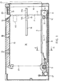
- Fig. 3 is a vertical cross section showing a card driving reference plane of the card reader shown in Fig. 1.
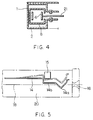
- Fig. 4. Is a IV-IV cross section of a card reader shown in Fig. 1.
- Fig. 5 is a diagram showing a positional relationship between the optical sensor and plate spring of the card reader shown in Fig. 1.
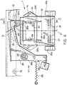
- Fig. 6 is a plan view showing a head support mechanism of a card reader of the present invention.
- Fig. 7 is a plan cross section showing the overall card reader shown in Fig. 6.
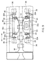
- Fig. 8 is a vertical cross section showing a head support mechanism cut out at III-III shown in Fig. 6.
- Fig. 9 is a side view of the head support mechanism shown in Fig. 8.
- Fig. 10 is a bottom view of showing the support mechanism of the lower magnetic head shown in Fig. 8.
- Fig. 11 is a vertical cross section showing a state in which two magnetic heads are displaced.
- Fig. 12 is a side view showing another embodiment for the head support mechanism of two magnetic heads.
- Fig. 13 is a plan view showing another embodiment for the position guiding member for a magnetic head.
- Fig. 14 is a side view of Fig. 13.
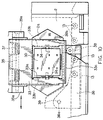
- Fig. 15 is an overall configuration including the IC contact block of a card reader of the present invention.
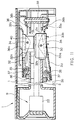
- Fig. 16 is a magnified diagram for an IC contact block moving means shown in Fig. 15.
- Fig. 17 is a schematic configuration describing the IC contact block movement shown in Fig. 16.
- Fig. 18 is a extended diagram of Fig. 15, in which gears convert the driving forces of a card reader shown in Fig. 15.
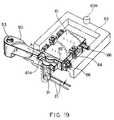
- Fig. 19 is a descriptive diagram showing another embodiment for the IC contact block movement.
- Figs. 1 - 3 show embodiments of the card reader of the present invention.
- the card reader in these embodiments is for a magnetic card, which is driven by a motor to transfer the magnetic card inserted from the card insertion slot to record / reproduce data on the magnetic card by means of a magnetic head.
- the magnetic head can be reproduction specific or capable of both recording and reproducing.
- Case 20 of the card reader is mounted with upper guiding frame 1 and lower guiding frame 2 (Fig. 3) which are made of a composite comprising sheet metal and molded.
- Card driving path 18 and driving reference plane 19 are formed in case 20.
- Magnetic head 40 is arranged in the middle of card driving path 18. The support mechanism and the like for this magnetic head 40 are described herein.
- a pressing member in accordance with the present invention is located between card insertion slot 16 on case 20 and magnetic head 40, such pressing member contacting the side surface of card 21 so that card 21 presses against driving reference plane 19.
- the pressing member is rotating member driven by, for example, driving motor 3 (See Fig. 15) which starts driving upon insertion of card 21.
- the pressing member is a flat surface of belt 6 with teeth.
- Belt 6 is held between transmission pulley 11 with gear, which is arranged between card insertion slot 16 and magnetic head 40 to press the side surface of card 21 against the driving reference plane 19 side.
- Card 21 is transferred on the flat surface of belt 6, thereby providing a card transfer means, and driving pulley 5 with a gear, which is rotatably driven by driving motor 3.
- Transmission pulley 11 is rotatably supported by shaft 9 at the end of pulley support arm 8 which is rotatably supported by shaft 7.
- Driving pulley 5 is positioned in the vicinity of the base of pulley support arm 8 and movably mounted on case 20. Between transmission pulley 11 and driving pulley 5, transfer pulley 12 with teeth, which transfer card 21 via belt 6 with teeth, is formed such that transfer pulley 12 dependently rotates via the teeth on belt 6 to press the side surface of card 21 with the flat surface of belt 6 with teeth against the card driving reference plane 19 side. That is, transfer pulley 12, arranged in the vicinity of transmission pulley 11, is rotatably supported by shaft 10, which is mounted onto pulley support arm 8.
- the horizontal cross section of pulley support arm 8 is shaped in a square with an open side as shown in Fig. 4.
- Belt 6 is arranged inside the pulley support arm 8.
- card 21 is inserted to the slot and plate spring 14 is lifted up, when photo sensor 15 detects the deformation, thereby moving motor 3.
- Plate spring 14 is fixed onto upper guiding flame 1.
- Projection 14a is projected over card driving pass 18.
- photo sensor 15 is actuated.
- Belt 6 is moved as driving pulley 5 is rotated via a deceleration gear train (described later) by the driving force of motor 3.
- Card 21 is further taken in the driving direction on belt 6 as driving pulley 5 is rotated via deceleration gear train (described later) by the driving force of motor 3.
- Coil spring 17 is mounted on the base end of pulley support arm 8.
- Card driving reference plane 19 comprises a plurality of rotatable rollers 13. In other words, card driving reference plane 19 is structured such that (the outer surface of) rotatable rollers 13 is slightly projected from a surface formed by a side mold portion of each of guiding frames 1, 2.
- card 21 When card 21 is inserted into card insertion slot 16, card 21 contacts projection 14a of plate spring 14 to push up actuator 14b of a photo sensor.
- photo sensor 15 detects the movement of actuator 14b, motor 3 is activated to rotate belt 6 counterclockwise, as shown in Fig. 1, via a deceleration gear train and pulley 5; that is, to rotate belt 6 in the direction in which card 21 is taken into the card reader.
- card 21 is inserted via card insertion as far as where pulley 11 is, card 21 is taken into the card reader by the driving force from belt 6.
- card 21 When the tip of card 21 taken into the card reader reaches point E indicated with the double dotted line in Fig. 1, card 21 is positioned nearly parallel with card driving reference plane 19 by two pairs of rollers 13 on card insertion slot 16 side and pulley 11, and are taken into the card reader straight to magnetic head 40.
- the magnetic strip on card 21 touches magnetic head 40, the magnetic head reads / writes the data on the magnetic strip.
- Transfer pulley 12 is arranged such that it projects slightly more than transmission pulley 11, thereby pulley 12 acts as the main feeder for the card transfer on belt 6 during the read /write mode of magnetic head 40. Instead of slightly more projecting transfer pulley 12 than transmission pulley 11, pulleys 11, 12 may be arranged in parallel in the card transfer direction.
- the rotational force of motor 3 is transmitted to drive pulley 5 to rotate belt 6, thus each of the pulleys 11, 12 are rotated.
- pulley 11 or pulley 12 may be rotated directly by motor 3.
- a plurality of rollers 13 are provided on card driving reference plane 19 to construct a row of rollers. The row of rollers may be replaced with a belt which moves as a card is driven.
- each roller 13 may be omitted and a mold surface may contact a card.
- card 21 is pushed in the card reader such that it projects within card driving path 18.
- the card reader includes magnetic heads 40, 50, which are supported such that they can move in the direction orthogonal to the card surface which conforms to the wave/warps of card 21, and a limiting lever, which acts as a limiting member in accordance with the present invention.
- Limiting lever 36 is positioned at the limited position (indicated with a solid line in Fig. 6) at which the amount of projection of the magnetic heads 40, 50 over card driving path 18 when card 21 is ejected to the outside of the card reader and does not contact magnetic heads 40, 50. Limiting lever 36 retreats from the limited position (see double dotted line in Fig. 6) when card 21 is inserted into the card reader and contacts magnetic heads 40, 50.
- the card reader as shown in Figs. 7 and 8, includes upper and lower guiding frames 1 and 2 which form card driving path 18, magnetic heads 40, 50, which are formed on the sides of the direction perpendicular to the card surface on card driving path 18, a card feeding mechanism by means of belt 6 arranged along one end of card driving path 18, and an insertion detecting sensor 110, which detects the fact that card 2 is inserted into the end of the slot.
- Head windows 1a, 2a are formed on upper and lower guiding frames 1, 2 where magnetic heads are arranged such that magnetic heads 40, 50 can be exposed to card driving path 18.
- Magnetic heads 40, 50 are arranged on the upper and lower sides of card driving path 18 as shown in Figs. 8 and 9.
- upper head 40 is for a 1-track magnetic strip
- lower head 50 is for a 3-track magnetic strip.
- the present invention is not limited to these. Different types of magnetic heads can be used to meet the different specifications of magnetic strips, of course. Also, it is acceptable that each magnetic head 40, 50 performs at least one of the recording or reproducing functions.
- Upper and lower magnetic heads 40, 50 are supported by upper and lower support plates 32, 33, as shown in Figs. 6 and 10, which are movable around axis 34 and shaped in square whose longer side is laid along the card driving direction.
- Upper support plate 32 is arranged opposite card driving path 18 of upper guiding frame 1; lower support plate 33 is arranged opposite card driving path 18 of lower guiding frame 2.
- head windows 32a, 33a constructed with through holes. At both ends of each head windows 32a, 33a, flanges 32b, 33b projects above the side of card driving path 18.
- Upper and lower magnetic heads 40, 50 are movably mounted on flanges 32b, 33b of upper and lower support plates 32, 33 around shaft 34.
- Upper and lower support plates 32, 33 are movably supported by upper and lower guiding frames 1 and 2 around shalt 35, 35 which are shaped in square with a long side laid along the card driving direction. Both ends of shalt 35, 35 are supported by shalt support blocks 35a, 35a molded onto upper and lower guiding frames 1, 2. Shaft 35, 35 is wound with spring 37 made of a coil spring. Spring 37, 37 transmits force from support plates 32, 33 such that magnetic heads 50 project into card driving path 18.
- lever bearings 32c, 33c which are curved in the direction away from card driving path 18, are formed.
- Lever bearings 32c, 33c limit the movement position for support plates 32, 33 by contacting limiting lever 36.
- the projection position of magnetic heads 40, 50 to card driving path 18 is limited by lever bearings 32c, 33c of support plates 32, 33.
- the projection position to card driving path 18 can be limited by magnetic heads 40, 50 directly contacting limiting lever 36.
- limiting lever 36 is arranged at the side of upper support plate 32 of upper guiding frame 1.
- Limiting lever 36 is nearly L shape and comprises support portion 36a, which is the center of the curved movement of 36, a contact roller 38, which is mounted at one end as a contact portion, limiting portion 36b, which contact lever bearings 32c, 33c formed in the vicinity of contact roller 38; and a spring mounting portion 36c, which is formed on the other end.
- Support portion 36a is movably mounted onto shalt 39 which is perpendicular to the card surface and mounted on upper frame 1.
- Contact roller 38 which is formed on limiting lever 36, is shaped such that its longer side is vertical to the card surface, comes in and out with respect to card driving path 18 as limiting lever 36 moves.
- Limiting portions 36b, 36b are positioned opposite card driving path 18 of upper and lower guiding frames 1, 2 and are shaped such that they are curved closer to card driving path 18. Therefore, limiting portion 36b, 36b can contact lever bearings 32c, 33c of each support plate 32, 33 as limiting lever 36 moves.
- limiting spring 26 which is made of heli coil spring as a transmission member, is mounted at spring mounting portion 36c of limiting lever 36.
- the other end of limiting spring 26 is mounted on the upper guiding frame 1 at a point closer the away from the slot end.
- Limiting spring 26 rotates limiting lever 36 clockwise as shown in Figs. 6 and 7 so that contact roller is projected into the card driving path; also, by pressing limiting portions 36b, 36b against lever bearings 32c, 33c, the projection position of magnetic heads 40, 50 is limited at the center of card driving path 18. At this projection position, it is ideal that magnetic heads 40, 50 are somewhat distanced while the end surfaces of magnetic heads 40, 50 are close together.
- limiting lever 36 is rotated clockwise by limiting spring 26.
- Contact roller 38 projects to card driving path 18 and limiting portions 36b, 36b are pressed against lever bearings 32c, 33c.
- upper and lower support plates 32, 33 cannot move with respect to card driving path 18, and at the same time, the head surfaces of magnetic heads 40, 50 are positioned where the head surfaces and the card surface correspond to each other, that is, the neutral position.
- a card transfer mechanism is driven as previously described and card 21 is taken further on belt 6, which is a card transfer means.
- the tip of card 21 contacts the head surfaces of magnetic heads 40, 50. Therefore, at the projection position of magnetic heads 40, 50, limited at the center of card driving path 18, the magnet heads are parted in a range which ensures the contact between the magnetic heads and the card, even when the tips of magnetic heads 40, 50 need to be somewhat distanced.
- Card 21 is guided along the head surface to enter the gap between upper and lower magnetic heads 40, 50, thus expanding heads 40, 50 while the card is being driven. At this time, magnetic heads 40, 50 are pressed against card 21 via springs 37, 37, thus ensuring the contact between the magnetic strip and the head surface. Magnetic data are read / written when the magnetic strip and the head surface contact while card 21 is being driven.
- the present embodiment describes an example in that the head surfaces contact each other at the neutral position before card 21 is inserted.
- the embodiment is not limited to this.
- the tips of support plates 32, 33 can be extended to form head contact limiting portions 32d, 33d such that head contact limiting portions 32d, 33d contact before card 21 is inserted.
- a contact limiting means can be formed for maintaining magnetic heads 40, 50 at a neutral position at which heads do not contact each other.
- head contact limiting portions 32d, 33d are designed to keep their tips away form each other, even in the state card 21 is not present, when the card is off the magnetic heads, which is provided with a small area of contact for head contact limiting portions 32d, 33d, which makes them extremely easier to return to the neutral position from the upper or lower position of card driving path 18, by limiting lever 36.
- magnetic heads 40, 50 may deviate from the center. This is because the head surfaces contact and are pressed by spring 37, having the head surfaces abrade each other; the heads keep their deviated positions. However, in this embodiment, limiting portions 36b, 36b move to contact lever bearings 32c, 33c; this sets supporting plates 32, 33 and magnetic heads 40, 50 to the center.
- limiting portions 36b, 36b are shaped to curve closer to card driving path 18; lever bearings 32c, 33c are shaped to curve away from card driving path 18. Even if support plate 32, 33 are largely deviated from the center, limiting portions 36b, 36b move to press one of the curvatures of lever beatings 32c, 33c with limiting portions 36b, 36b on one side, support plates 32, 33 can return to the neutral position. With this recovery, magnetic heads 40, 50 are kept at a distance. The tip of card 21 inserted into the card reader contacts the side surfaces of magnetic heads 40, 50, thus maintaining a smooth driving of card 21.
- the head surfaces of magnetic heads 40, 50 when the head surfaces of magnetic heads 40, 50 contact each other and are deviated from the neutral position, the head surfaces of magnetic heads 40, 50 must be slid in the direction of the longer side of the contact surfaces to retain their neutral positions. As shown in Fig. 12, the magnetic heads can be returned to their neutral positions extremely easy using limiting lever 36 if the head surfaces of magnetic heads 40, 50 are set such that they do not contact while head contact limiting portions 32d, 33d are set to contact, and the area of contact is made small for head contact limiting portions 32d, 33d.
- both magnetic heads 40, 50 can be moved in the yawing and the card surface direction; they can contact card 21 even more closely; this makes it possible to read / write magnetic data accurately.
- limiting lever 36 is used as a limiting member which yaws.
- movable lever 125 as shown in Figs. 13 and 14, which is movable in the card driving direction can be used.
- contactingly movable lever 125 comprises contacts portion 125a which contact the tip of card 21 and limiting portion 125b which enters between the head surfaces of upper and lower magnetic heads 40, 50.
- a limiting spring made of helicoid spring 26' is attached on a part of contactingly movable lever 125. Note that in this embodiment, the structure of upper and lower magnetic heads 40, 50 or support plates 32, 33 or guiding frames 1,2 and the like are the same as the above embodiment, therefore, is not described herein.
- limiting portion 125b is entered between head surfaces using the force transmitted from limiting spring 26' to set magnetic heads 40, 50 in the middle. Then, card 21 is inserted and contact portion 125a is pushed and limiting portion 125b is pushed out of magnetic heads 40, 50. When card 21 is ejected, limiting portion 125b again enters between magnetic heads 40, 50 to set them in the center.
- card 21 is transferred from card insertion slot 16 to where data is read/ written using the rotational (driving) force of motor 3.
- Data is read/ written by contacting IC contact 610 (See Fig. 17,) which is held by IC contact block 61 formed on an IC terminal exposed manner on card 21.
- This embodiment includes a card transfer means by belt 6, which transfers card 21 between card insertion slot 16 and read / write position; and a contact block moving means 60, which moves IC contact block 61 between the contact position and the retreat position.
- the load torque which is required for moving IC contact block 61 to the contact point with card 21 is set larger than that which is required for moving belt 6, which is the load torque of transfer means for the transfer of card 21, and is smaller than that which is required when the card 21 is inserted into the read / write position which is the end of its movement.
- a driving force switching mechanism 70 is formed for transmitting rotational force of motor 3 to the side where each load torque is smaller.
- Card transfer means comprises four pulleys 5, 11, 111, 112 and drive belt 6 which is held by each pulley.
- Pulley 5 transmits the rotational force of motor 3 which is transmitted from drive force switching mechanism 70 via gear 49 to drive belt 6.
- Pulley 11 is mounted at the tip of arm 8 which is rotatable around shaft 9; driving belt 6 is pressed onto one end of card 21 by being stretched in counterclockwise by spring 17 (See Fig. 1.)
- Pulleys 111, 112 are mounted at the tip of rotatable arms 87, 88 around shalt 86. They are pulled by each of springs 89, 90 to press drive belt 6 against one end of card 21.
- Drive belt 6 is the same as in the previous embodiment in that it transfers card 21 from card insertion slot 16 to the read / write position by pressing card 21 against eight rollers 13, which makes a card reference plane.
- Contact block moving means 60 includes an arm 62, which is rotatable within a range of predetermined angles, a cam lever 63, which moves IC contact block 61 from the retreat position from card driving path 18 to the contact point with the card, two return coil springs 64, which return the IC contact block 61 from the contact position to the retreat position.
- the above contact position (position indicated with a double-dotted line in Fig. 17) is where IC contact 610 of IC contact block 61 resiliently contacts the IC terminal exposed on card 21.
- the retreat position (position indicated with a solid line in fig. 17) is where IC contact 610 is apart from the IC terminal, which opens a way for transferring card 21.
- Each shalt 65 supports four pairs of IC contacts 610 of a resilient spring structure.
- Sleeve 66 is rotatably fitted onto both ends of each shalt 65.
- Each sleeve 66 is inserted into U groove 67 formed on upper guiding frame 1. Therefore, IC contact block 61 can move only in the depth direction of each U groove, that is in the direction vertical to the moving direction of card 21.
- cam lever 63 is shaped nearly a rectangle with an open side.
- Cam lever 63 is held on upper guiding frame 1 in the transfer direction of card 21 slidably at a predetermined distance.
- Cam portion 63b is formed at four places opposite each sleeve 66 of cam lever 63. Therefore, if cam lever 63 slides, each sleeve 66 is pushed down toward the opening of U grooves as shown in Fig. 17. In other words, IC contact block 61 is moved to the contact position.
- Each return spring 64 is arranged in the state in which they are compressed between spring base 64a, 64a formed in the center of both ends of IC contact block 61 and upper guiding frame 1. Therefore, each return spring 64 pushes each sleeve 66 up toward the bottom of each of the U grooves 67. In other words, if the pressure from cam lever 63 is released, IC contact block 61 is moved to the retreat position.
- a long hole 62a is formed in the center of arm 62. Convexity 63b formed on cam lever 63 is inserted into the long hole 62a. Therefore, if arm 62 is rotated around shaft 68, cam lever 63 slides. At the tip surface of arm 62, gear portion 62b is formed. Gear portion 62b is engaged with a small gear 54 of deceleration gear train 59. Therefore, if second output gear 58 of drive switch mechanism is rotated, the rotation is transmitted to gear portion 62b via large gear 51, gear 52a, small gear 52b, gear 53, and small gear 54 of deceleration gear train 59. Arm 62 is rotated by these gears.
- coil spring 165 One end of coil spring 165 is positioned at a predetermined position on arm 62; the other end of coil spring 165 is mounted on upper guiding frame 1. Coil spring 165 pulls arm 62 in the direction apart from IC contact block 61.
- the load torque which works on contact block moving means 60, is increased when IC contact block 61 is moved to the contact position; it is decreased when IC contact block 61 is moved to the retreat position.
- the load torque, which is required to move contact block 61 to the contact position is set larger than that is required for transferring card 21 and set smaller than that is required when card 21 is at the read /write position, which is the end of movement.
- the load torque which is required for moving contact block 61 to the retreat position is set smaller than that is required for transferring card 21 by adjusting the magnitude of force of coil spring 165.
- photo sensor 160 is installed in the vicinity of arm 62. This photo sensor 160 detects the fact that arm 62 is rotated to the contact position with IC contact block 61.
- Driving force switching mechanism 70 is a gear connection mechanism including first output gear 57 and second output gear 58 which transfer the rotational force of motor 3 to contact block moving means 60. Of the first and second output gears 57, 58, the output gear with a larger load torque is stopped, thus the output gear with a smaller torque is rotated.
- This gear connection mechanism comprises, as shown in Fig. 18, driving force division gear unit 400 arranged relatively rotatably on the same shalt between the first and second output gears 57, 58.
- Driving force division gear unit 400 includes driving gear 41, which is rotated by motor 3, revolving shalt 41a, which is fitted through the eccentric position of driving gear 41 and is relatively rotatably mounted at the eccentric position, first division gear 42, which is fixed at one end of revolving shaft 41a; and second division gear 43, which is fixed on the other end of the revolving shaft 41a.
- First division gear 42 is engaged with first output gear 57 side. In other words, it is acceptable if first division gear 42 is engaged with first output gear 57 directly or indirectly. In this embodiment, first division gear 42 directly transmits the rotational force for engagement with first output gear 57.
- second division gear 43 is engaged with second output gear 58 side. In other words, it is acceptable that second division gear 43 is engaged with the side of second output gear 58 directly or indirectly. In this embodiment, second division gear 43 transmits the rotational force for indirect engagement with second output gear 58 via pinion gear 44.
- Pinion gear 44 is installed relatively rotatably at the eccentric position of drive gear 41 in the same manner as second division gear 43. Note that in Fig. 18, second output gear 58 and pinion gear 44 are apart; they are illustrated that way to simplify the drawing. However, they are engaged in actual use.)
- Rotational force of motor 3 is transmitted to drive gear 41 via umbrella gear 45, large gear 46, small gear 47 respectively. If drive gear 41 is rotated, each division gear 42, 43 and pinion gear 44, which are installed at the eccentric position of drive gear 41, revolve around each output gear 57, 58.
- First output gear 57 transmits the rotational force to the card transfer means. It receives a predetermined load torque when the card reaches the read / write position, that is, the transfer end position of card 21 as shown in Fig. 15.
- second output gear 58 transmits the rotational force to contact block moving means 60. It receives the load torque which is required for moving contact block 61.
- each load torque is set by adjusting the speed ratio of the gear train of the card transfer means side to the contact block moving means 60 side and adjusting the spring force of coil spring 65 of contact block moving means 60.
- the load torque which is required to move contact block 61 is set significantly smaller than that is required when card 21 is at the read /write position, which is the end of the path.
- umbrella gear 45 is fixed onto output shaft of motor 3.
- large gear 465 and small gear 47 are a composite gear which rotates integrally.
- the load torque which is required to move IC contact block 61 is set larger than that required for transfer of card 21.
- the minimum value for the load torque while IC contact block 61 moves is larger than the maximum value of the load torque required for transfer of card 21.
- Second output get 58 receives a larger load torque than first output gear 57.
- second output gear 58 which receives a larger load torque, is stopped; pinion gear 44, which revolves second output gear 58, and second division gear 43 revolve. Therefore, first division gear 42, which is connected to second division gear 43 by revolving shaft 41a revolves; first output gear 57 which is engaged with first division gear 42 rotates.
- first and second division gears 42, 43 revolve around first and second output gears 57, 58, of these first and second output gears 57, 58, second division gear 43, which is engaged with second output gear 58 side and is stopped due to receiving a larger load torque, revolves.
- This revolution is transmitted to the other first division gear 42 via revolving shalt 41a to rotate first output gear 57 which receives a smaller load torque from first and second output gears 57, 58.
- the rotational force of first output gear 57 is transmitted to gear 49 of card transfer means. It rotate belt 6 by rotating pulley 5 via gear 5a. By doing so, card 21 which is inserted into card insertion slot 16 is taken into the card reader as card 21 is pressed onto each rollers 13 to be transferred to the read / write position. Card 21 is transferred smoothly while it is transferred a power relationship between the load torque which is required to move IC contact block 61 and load torque which transfers card 21 is maintained.
- the rotational force of motor 3 is transmitted only to the card transfer means side. In other words, the rotational force is not transferred to moving means 60 until card 21 is transferred to the read / write position.
- the card transfer means is driven only.
- first output gear 57 receives a larger load torque than second output gear 58.
- First output gear 57 is stopped at this time and first division gear 42 which revolves around first output gear 57 revolves. Therefore, second division gear 43, which is connected to first division gear 42 via revolving shaft 41a revolves, rotating second output gear 58 which is engaged with first division gear 42.
- first division gear 42 which is engaged with the side of first output gear 57, revolves.
- First output gear 57 is stopped when receiving a larger load from one of them. This rotation is transmitted to second division gear 43 via revolving shaft 41a.
- Second output gear 58 which receives a smaller load torque from one of first and second output gears is rotated via pinion gear 44.
- the rotational force of the second output gear is transmitted to large gear 51 of contact block moving means 60. Then, it is deceleratingly transmitted to gear 52a, small gear 52b, large gear 53, and small gear 54 respectively.
- Arm 62 is driven in this way.
- Cam lever 63 is slid to move IC contact block 64 to the contact position with card 21.
- photo sensor 66 detects that IC contact block 64 reached the contact position, that is, arm 62 is moved to a predetermined position, rotation of motor 3 is stopped. In this state, "detent" torque works on motor 3. Arm 62 will not be retracted by coil spring 165.
- IC contact block 61 is held at the contact position of card 21.
- arm 62 of contact block moving means 60 and cam lever 63 are independent. They can be integrated, of course.
- rotational force between motor 3 and drive force division gear unit 400, between first output gear 57 and second output gear 58, and between second output gear 58 and arm 62 pulley are transmitted using a flat gear or an umbrella gear.
- deceleration transmission methods such as worm gears or belts and the like can be used as well.
- FIG. 19 Another embodiment in which card transfer and IC contact block movement switching, that is when an IC contact block contacts the IC terminal when the card is transferred to a predetermined position, as ensured is shown in Fig. 19.
- projection portion 61a is formed at IC contact block 61.
- a movement prevention member 90 is formed to prevent the above the IC contact block 61, which is engaged with projection portion 61a, is moved from the retreat position, which is away from card driving path 18, to the contact point with IC terminal formed on card 21.
- Movement prevention member 90 is movably installed onto support shaft 93 formed on a guide frame. It is engaged with the front end of card 21 and comprises card engagement portion 91, which is moved by the above card 21.
- the IC card reader is used for the magnetic card reader as well.
- magnetic head 40 can be omitted and the card reader can be used specifically for IC cards.
- a pressing member which contacts a side of a card such that the card is pressed against a card driving reference plane, is positioned between a card insertion slot and a recording/reproducing means such as a head and the like. Consequently, the card is driven while being pressed against the card driving reference plane by the pressing member, which results in straightening the direction of the card immediately after insertion; hence, the direction of the card can be corrected in a short driving distance. This enables one to shorten the overall length of the card reader and to reduce the size of the card reader.
- the structure of the card reader can be such that when the magnetic card is ejected and does not contact a magnetic head, a limiting member is positioned at a limiting position at which projection of the magnetic head in a card driving path is limited, and when the magnetic card is inserted and contacts the magnetic head, the limiting member is retreated from the limiting position.
- the head surface of the magnetic head is positioned at a neutral position even after a deformed card is ejected; thus, it is unnecessary to correct the deformed card with the pressure inserted from the magnetic head.
- the head pressure can be reduced, therefore, an increase in the size of a motor which drives the card, caused by an increase in the load of driving the card, can be prevented.
- a driving force switching mechanism is formed between a motor and, a card transfer means and a contact block moving means. It enables to transmit the rotational force of the motor to the card transfer means or the contact block moving means according to the correlation in the amount of the load torque affecting the card transfer means and the contact block moving means.
- both transferring the card and driving the IC contact block can be separately performed by one motor; by reducing the number of components, in turn, low cost and minimizing the size of the apparatus can be accomplished.
Landscapes
- Engineering & Computer Science (AREA)
- Physics & Mathematics (AREA)
- General Physics & Mathematics (AREA)
- Theoretical Computer Science (AREA)
- Artificial Intelligence (AREA)
- Computer Vision & Pattern Recognition (AREA)
- Conveying Record Carriers (AREA)
Applications Claiming Priority (9)
| Application Number | Priority Date | Filing Date | Title |
|---|---|---|---|
| JP304637/96 | 1996-11-15 | ||
| JP30463796A JP3394874B2 (ja) | 1996-11-15 | 1996-11-15 | カードリーダ |
| JP30463796 | 1996-11-15 | ||
| JP312250/96 | 1996-11-22 | ||
| JP31225096A JP3375840B2 (ja) | 1996-11-22 | 1996-11-22 | カードリーダ |
| JP31225096 | 1996-11-22 | ||
| JP49342/97 | 1997-03-04 | ||
| JP4934297 | 1997-03-04 | ||
| JP04934297A JP3326351B2 (ja) | 1997-03-04 | 1997-03-04 | Icカードリーダ |
Publications (2)
| Publication Number | Publication Date |
|---|---|
| EP0843274A2 true EP0843274A2 (de) | 1998-05-20 |
| EP0843274A3 EP0843274A3 (de) | 2004-03-03 |
Family
ID=27293607
Family Applications (1)
| Application Number | Title | Priority Date | Filing Date |
|---|---|---|---|
| EP97402756A Withdrawn EP0843274A3 (de) | 1996-11-15 | 1997-11-17 | Kartenleser |
Country Status (3)
| Country | Link |
|---|---|
| US (1) | US6250552B1 (de) |
| EP (1) | EP0843274A3 (de) |
| GB (1) | GB2319375B (de) |
Cited By (2)
| Publication number | Priority date | Publication date | Assignee | Title |
|---|---|---|---|---|
| WO2006129170A1 (en) * | 2005-06-01 | 2006-12-07 | Nokia Corporation | Electronic module reader |
| US11176530B2 (en) * | 2019-04-24 | 2021-11-16 | Panasonic Intellectual Property Management Co., Ltd. | Payment terminal |
Families Citing this family (23)
| Publication number | Priority date | Publication date | Assignee | Title |
|---|---|---|---|---|
| US6938825B1 (en) * | 1989-04-24 | 2005-09-06 | Ultracard, Inc. | Data system |
| US6934098B2 (en) * | 1998-04-09 | 2005-08-23 | Dcard, Inc. | Data card with a full circular track for alignment and amplitude calibration |
| JP2000148925A (ja) * | 1998-11-06 | 2000-05-30 | Matsushita Electric Ind Co Ltd | カードリーダ及び電子機器 |
| JP2000293813A (ja) * | 1999-04-08 | 2000-10-20 | Sankyo Seiki Mfg Co Ltd | 多チャンネル磁気ヘッド及びその製造方法及びそれを用いた磁気カードリーダ |
| JP3602379B2 (ja) * | 1999-09-08 | 2004-12-15 | 株式会社三協精機製作所 | 磁気カードリーダにおけるヘッド保持機構 |
| US8397998B1 (en) * | 1999-10-23 | 2013-03-19 | Ultracard, Inc. | Data storage device, apparatus and method for using same |
| DE60127468T2 (de) * | 2000-01-24 | 2008-01-31 | Nidec Sankyo Corp. | Manueller Chipkartenleser |
| GB2362014B (en) * | 2000-05-05 | 2004-07-07 | Asahi Seiko Co Ltd | Memory card handling apparatus |
| DE10112061B4 (de) * | 2001-03-14 | 2007-08-30 | Siemens Ag | Aufnahmevorrichtung für in Fahrzeugen verwendete, der personenbezogenen Erfassung von Fahrtdaten dienende Chipkarten |
| JPWO2003015083A1 (ja) * | 2001-08-03 | 2004-12-02 | 松下電器産業株式会社 | カードリーダ |
| ATE350727T1 (de) * | 2001-08-24 | 2007-01-15 | Cubic Corp | Universelle ticket-transportvorrichtung |
| JP2003086274A (ja) * | 2001-09-13 | 2003-03-20 | Honda Tsushin Kogyo Co Ltd | メモリーカード用コネクタ |
| JP3855804B2 (ja) * | 2002-03-04 | 2006-12-13 | 旭精工株式会社 | カード回収装置を備えたカード処理装置 |
| JP4224809B2 (ja) * | 2003-03-03 | 2009-02-18 | 旭精工株式会社 | Icカード処理装置の通信基板装着装置 |
| JP4522072B2 (ja) * | 2003-10-22 | 2010-08-11 | 日立オムロンターミナルソリューションズ株式会社 | カード処理装置 |
| GB0420443D0 (en) * | 2004-09-14 | 2004-10-20 | Ncr Int Inc | A card reader |
| US7784700B2 (en) * | 2005-11-10 | 2010-08-31 | Datacard Corporation | De-bowing personalized cards |
| US7753275B2 (en) * | 2007-09-17 | 2010-07-13 | Verifone, Inc. | Magnetic card reader, especially for point of sale terminals |
| JP5740644B2 (ja) * | 2010-10-08 | 2015-06-24 | 日本電産サンキョー株式会社 | 電子機器装置、そのペアリング処理方法及びペアリング監視方法 |
| DE102011015264A1 (de) * | 2010-12-20 | 2012-06-21 | Continental Automotive Gmbh | Bordinformationssystem für Fahrzeuge |
| US9381695B2 (en) | 2013-05-23 | 2016-07-05 | Entrust Datacard Corporation | Card de-bowing mechanism |
| US9436856B2 (en) | 2014-12-23 | 2016-09-06 | Verifone, Inc. | Magnetic stripe card reader |
| US9721124B1 (en) | 2016-02-03 | 2017-08-01 | Verifone, Inc. | Magnetic card reader |
Citations (17)
| Publication number | Priority date | Publication date | Assignee | Title |
|---|---|---|---|---|
| US3866827A (en) * | 1972-02-17 | 1975-02-18 | Tokushu Seiko Co Ltd | Magnetic card apparatus |
| US4358103A (en) * | 1977-02-04 | 1982-11-09 | Canon Kabushiki Kaisha | Magnetic card transporting apparatus |
| US4443049A (en) * | 1978-12-27 | 1984-04-17 | Compagnie Internationale Pour L'informatique Cii-Honeywell Bull (Societe Anonyme) | Connector for portable objects such as credit cards |
| FR2552252A1 (fr) * | 1983-09-21 | 1985-03-22 | Dassault Electronique | Lecteur mixte pour cartes a piste magnetique et/ou a puce electronique |
| US4684794A (en) * | 1984-11-15 | 1987-08-04 | Nixdorf Computer Ag | Transport device for card-like recording medium |
| EP0274684A1 (de) * | 1986-12-12 | 1988-07-20 | Omron Tateisi Electronics Co. | Chipkartenleser |
| DE3706836A1 (de) * | 1987-03-03 | 1988-09-15 | Nixdorf Computer Ag | Vorrichtung zum abtasten von identitaetskarten |
| EP0296590A2 (de) * | 1987-06-23 | 1988-12-28 | Omron Tateisi Electronics Co. | Verarbeitungsgerät für optische Karten |
| US4795891A (en) * | 1986-03-14 | 1989-01-03 | Omron Tateisi Electronics Co. | Card guide device |
| EP0311118A1 (de) * | 1987-10-09 | 1989-04-12 | Omron Tateisi Electronics Co. | Lese-/Schreibgerät für eine IC-Karte |
| JPH0383750A (ja) * | 1989-08-25 | 1991-04-09 | Olympus Optical Co Ltd | 光カード往復搬送装置 |
| US5017764A (en) * | 1987-12-28 | 1991-05-21 | Olympus Optical Co., Ltd. | Apparatus for driving card-like record medium |
| EP0488365A2 (de) * | 1990-11-30 | 1992-06-03 | Olympus Optical Co., Ltd. | Informationsaufzeichnungs- und -wiedergabegerät für Karten zur Informationsaufzeichnung |
| EP0491321A1 (de) * | 1990-12-17 | 1992-06-24 | Wilfried Rinas | Vorrichtung zum Lesen und/oder Schreiben von Markierungen, Informationen od. dgl. auf Karten |
| JPH0744659A (ja) * | 1993-07-29 | 1995-02-14 | Nec Corp | 手動カードリーダ |
| US5466914A (en) * | 1992-04-24 | 1995-11-14 | Olympus Optical Co., Ltd. | Recording-reproducing apparatus with a mechanism for preventing successive insertion of two cards |
| JPH08171616A (ja) * | 1994-12-19 | 1996-07-02 | Shinei Diecast Kogyo Kk | カード装着装置 |
Family Cites Families (12)
| Publication number | Priority date | Publication date | Assignee | Title |
|---|---|---|---|---|
| US3521880A (en) * | 1968-12-30 | 1970-07-28 | Honeywell Inc | Processing station with document handling and aligning means |
| GB8407660D0 (en) * | 1984-03-23 | 1984-05-02 | Gec Traffic Automation | Magnetic card reading equipment |
| JPH01108693A (ja) * | 1987-10-21 | 1989-04-25 | Omron Tateisi Electron Co | Icカードリーダライタ |
| JPH0525006Y2 (de) * | 1987-12-18 | 1993-06-24 | ||
| FR2640780A1 (fr) * | 1988-12-20 | 1990-06-22 | Cit Alcatel | Lecteur de carte a puce |
| JP3113691B2 (ja) * | 1991-03-30 | 2000-12-04 | アマノ株式会社 | ヘッド反転機能を備えた磁気カードリーダ |
| US5331138A (en) * | 1992-11-03 | 1994-07-19 | American Magnetics Corp. | Hybrid card reader |
| ES2135505T3 (es) * | 1994-05-07 | 1999-11-01 | Scheidt & Bachmann Gmbh | Dispositivo para la escritura de soportes de datos con forma de tarjeta. |
| GB9422803D0 (en) * | 1994-11-11 | 1995-01-04 | At & T Global Inf Solution | A card reader |
| US5698832A (en) * | 1995-03-31 | 1997-12-16 | Neuron Corporation | Magnetic card reading apparatus |
| JPH0950492A (ja) * | 1995-08-09 | 1997-02-18 | Olympus Optical Co Ltd | 情報処理装置 |
| US5837991A (en) * | 1996-03-08 | 1998-11-17 | Card Technology Corporation | Card transport mechanism and method of operation |
-
1997
- 1997-11-13 US US08/970,038 patent/US6250552B1/en not_active Expired - Fee Related
- 1997-11-17 GB GB9724268A patent/GB2319375B/en not_active Expired - Fee Related
- 1997-11-17 EP EP97402756A patent/EP0843274A3/de not_active Withdrawn
Patent Citations (17)
| Publication number | Priority date | Publication date | Assignee | Title |
|---|---|---|---|---|
| US3866827A (en) * | 1972-02-17 | 1975-02-18 | Tokushu Seiko Co Ltd | Magnetic card apparatus |
| US4358103A (en) * | 1977-02-04 | 1982-11-09 | Canon Kabushiki Kaisha | Magnetic card transporting apparatus |
| US4443049A (en) * | 1978-12-27 | 1984-04-17 | Compagnie Internationale Pour L'informatique Cii-Honeywell Bull (Societe Anonyme) | Connector for portable objects such as credit cards |
| FR2552252A1 (fr) * | 1983-09-21 | 1985-03-22 | Dassault Electronique | Lecteur mixte pour cartes a piste magnetique et/ou a puce electronique |
| US4684794A (en) * | 1984-11-15 | 1987-08-04 | Nixdorf Computer Ag | Transport device for card-like recording medium |
| US4795891A (en) * | 1986-03-14 | 1989-01-03 | Omron Tateisi Electronics Co. | Card guide device |
| EP0274684A1 (de) * | 1986-12-12 | 1988-07-20 | Omron Tateisi Electronics Co. | Chipkartenleser |
| DE3706836A1 (de) * | 1987-03-03 | 1988-09-15 | Nixdorf Computer Ag | Vorrichtung zum abtasten von identitaetskarten |
| EP0296590A2 (de) * | 1987-06-23 | 1988-12-28 | Omron Tateisi Electronics Co. | Verarbeitungsgerät für optische Karten |
| EP0311118A1 (de) * | 1987-10-09 | 1989-04-12 | Omron Tateisi Electronics Co. | Lese-/Schreibgerät für eine IC-Karte |
| US5017764A (en) * | 1987-12-28 | 1991-05-21 | Olympus Optical Co., Ltd. | Apparatus for driving card-like record medium |
| JPH0383750A (ja) * | 1989-08-25 | 1991-04-09 | Olympus Optical Co Ltd | 光カード往復搬送装置 |
| EP0488365A2 (de) * | 1990-11-30 | 1992-06-03 | Olympus Optical Co., Ltd. | Informationsaufzeichnungs- und -wiedergabegerät für Karten zur Informationsaufzeichnung |
| EP0491321A1 (de) * | 1990-12-17 | 1992-06-24 | Wilfried Rinas | Vorrichtung zum Lesen und/oder Schreiben von Markierungen, Informationen od. dgl. auf Karten |
| US5466914A (en) * | 1992-04-24 | 1995-11-14 | Olympus Optical Co., Ltd. | Recording-reproducing apparatus with a mechanism for preventing successive insertion of two cards |
| JPH0744659A (ja) * | 1993-07-29 | 1995-02-14 | Nec Corp | 手動カードリーダ |
| JPH08171616A (ja) * | 1994-12-19 | 1996-07-02 | Shinei Diecast Kogyo Kk | カード装着装置 |
Non-Patent Citations (3)
| Title |
|---|
| PATENT ABSTRACTS OF JAPAN vol. 015, no. 253 (M-1129), 27 June 1991 (1991-06-27) & JP 03 083750 A (OLYMPUS OPTICAL CO LTD), 9 April 1991 (1991-04-09) * |
| PATENT ABSTRACTS OF JAPAN vol. 1995, no. 05, 30 June 1995 (1995-06-30) & JP 07 044659 A (NEC CORP), 14 February 1995 (1995-02-14) * |
| PATENT ABSTRACTS OF JAPAN vol. 1996, no. 11, 29 November 1996 (1996-11-29) -& JP 08 171616 A (SHINEI DIECAST KOGYO KK;T R D:KK), 2 July 1996 (1996-07-02) * |
Cited By (5)
| Publication number | Priority date | Publication date | Assignee | Title |
|---|---|---|---|---|
| WO2006129170A1 (en) * | 2005-06-01 | 2006-12-07 | Nokia Corporation | Electronic module reader |
| US7258278B2 (en) | 2005-06-01 | 2007-08-21 | Nokia Corporation | Electronic module reader |
| US11176530B2 (en) * | 2019-04-24 | 2021-11-16 | Panasonic Intellectual Property Management Co., Ltd. | Payment terminal |
| US20220012705A1 (en) * | 2019-04-24 | 2022-01-13 | Panasonic Intellectual Property Management Co., Ltd. | Payment terminal |
| US11935026B2 (en) * | 2019-04-24 | 2024-03-19 | Panasonic Intellectual Property Management Co., Ltd. | Payment terminal |
Also Published As
| Publication number | Publication date |
|---|---|
| US6250552B1 (en) | 2001-06-26 |
| GB2319375B (en) | 2000-09-06 |
| GB9724268D0 (en) | 1998-01-14 |
| GB2319375A (en) | 1998-05-20 |
| EP0843274A3 (de) | 2004-03-03 |
Similar Documents
| Publication | Publication Date | Title |
|---|---|---|
| US6250552B1 (en) | Card reader having means for reducing the size of the card reader | |
| JP3113691B2 (ja) | ヘッド反転機能を備えた磁気カードリーダ | |
| US5331144A (en) | Card reader-writer | |
| EP0774732A2 (de) | Vorrichtung zur Kartenverarbeitung | |
| EP0381137A3 (de) | Vorrichtung zum Bedrucken eines Passes und Verfahren zum Umblättern der Seiten eines Passes | |
| US7634781B2 (en) | Recording medium driving device | |
| JP4210217B2 (ja) | Icカードリーダ | |
| EP0146587B1 (de) | Modul zum anbringen von magnetstreifenzeichen | |
| US4701817A (en) | Loading and ejecting mechanism for a magnetic tape cassette apparatus | |
| JPH08504983A (ja) | モジュール式カード読み取り/書き込み装置 | |
| JPS6292267A (ja) | 情報記録再生装置 | |
| US6776338B2 (en) | IC card reader | |
| JPH04295981A (ja) | カード載置装置 | |
| US4501959A (en) | Method and apparatus for aligning flat data supports | |
| US5491679A (en) | Information recording and/or reproducing apparatus with shutter member and shuttle linked for movement together | |
| JP2933017B2 (ja) | カードリーダおよびカード取り込み方法 | |
| JPS6057112B2 (ja) | 磁気カ−ド搬送装置 | |
| JPH02281464A (ja) | カードリーダライタ | |
| JPH0413738Y2 (de) | ||
| JP3559438B2 (ja) | 磁気ヘッド保持機構 | |
| US5029028A (en) | Single-motor changing tape player | |
| JP3733193B2 (ja) | 磁気カードリーダ | |
| JP2924967B2 (ja) | 通帳取扱装置 | |
| US5986849A (en) | Tape player having a cam and a mode detecting gear | |
| JPS6292274A (ja) | 情報記録再生装置 |
Legal Events
| Date | Code | Title | Description |
|---|---|---|---|
| PUAI | Public reference made under article 153(3) epc to a published international application that has entered the european phase |
Free format text: ORIGINAL CODE: 0009012 |
|
| AK | Designated contracting states |
Kind code of ref document: A2 Designated state(s): AT BE CH DE DK ES FI FR GB GR IE IT LI LU MC NL PT SE |
|
| AX | Request for extension of the european patent |
Free format text: AL;LT;LV;MK;RO;SI |
|
| PUAL | Search report despatched |
Free format text: ORIGINAL CODE: 0009013 |
|
| AK | Designated contracting states |
Kind code of ref document: A3 Designated state(s): AT BE CH DE DK ES FI FR GR IE IT LI LU MC NL PT SE |
|
| AX | Request for extension of the european patent |
Extension state: AL LT LV MK RO SI |
|
| STAA | Information on the status of an ep patent application or granted ep patent |
Free format text: STATUS: THE APPLICATION IS DEEMED TO BE WITHDRAWN |
|
| AKX | Designation fees paid |
Designated state(s): DE FR |
|
| 18D | Application deemed to be withdrawn |
Effective date: 20040602 |