EP0838776A2 - Benutzereingabeabtastvorrichtung - Google Patents
Benutzereingabeabtastvorrichtung Download PDFInfo
- Publication number
- EP0838776A2 EP0838776A2 EP97308417A EP97308417A EP0838776A2 EP 0838776 A2 EP0838776 A2 EP 0838776A2 EP 97308417 A EP97308417 A EP 97308417A EP 97308417 A EP97308417 A EP 97308417A EP 0838776 A2 EP0838776 A2 EP 0838776A2
- Authority
- EP
- European Patent Office
- Prior art keywords
- articulating member
- articulating
- recited
- user
- manipulation
- Prior art date
- Legal status (The legal status is an assumption and is not a legal conclusion. Google has not performed a legal analysis and makes no representation as to the accuracy of the status listed.)
- Granted
Links
Images

Classifications
-
- G—PHYSICS
- G05—CONTROLLING; REGULATING
- G05G—CONTROL DEVICES OR SYSTEMS INSOFAR AS CHARACTERISED BY MECHANICAL FEATURES ONLY
- G05G9/00—Manually-actuated control mechanisms provided with one single controlling member co-operating with two or more controlled members, e.g. selectively, simultaneously
- G05G9/02—Manually-actuated control mechanisms provided with one single controlling member co-operating with two or more controlled members, e.g. selectively, simultaneously the controlling member being movable in different independent ways, movement in each individual way actuating one controlled member only
- G05G9/04—Manually-actuated control mechanisms provided with one single controlling member co-operating with two or more controlled members, e.g. selectively, simultaneously the controlling member being movable in different independent ways, movement in each individual way actuating one controlled member only in which movement in two or more ways can occur simultaneously
- G05G9/047—Manually-actuated control mechanisms provided with one single controlling member co-operating with two or more controlled members, e.g. selectively, simultaneously the controlling member being movable in different independent ways, movement in each individual way actuating one controlled member only in which movement in two or more ways can occur simultaneously the controlling member being movable by hand about orthogonal axes, e.g. joysticks
-
- G—PHYSICS
- G06—COMPUTING; CALCULATING OR COUNTING
- G06F—ELECTRIC DIGITAL DATA PROCESSING
- G06F3/00—Input arrangements for transferring data to be processed into a form capable of being handled by the computer; Output arrangements for transferring data from processing unit to output unit, e.g. interface arrangements
- G06F3/01—Input arrangements or combined input and output arrangements for interaction between user and computer
- G06F3/03—Arrangements for converting the position or the displacement of a member into a coded form
- G06F3/033—Pointing devices displaced or positioned by the user, e.g. mice, trackballs, pens or joysticks; Accessories therefor
- G06F3/038—Control and interface arrangements therefor, e.g. drivers or device-embedded control circuitry
- G06F3/0383—Signal control means within the pointing device
Definitions
- the invention relates to the field of user-manipulable apparatus for providing a user input, for example for moving a symbol, such as a cursor, on a display in computer graphical user interface systems.
- Mice have been commonly used as user-manipulable GUI apparatus. Using a mouse, a user directs the movement of a cursor across a display screen by corresponding manual mouse movements.
- a TrackPoint-type device as supplied by IBM Corporation (hereinafter "TrackPoint-type device” or “TrackPoint device”; “Trackpoint” and “Trackpoint III” are trademarks of IBM Corporation) has been mounted in-keyboard in many laptop computers.
- a TrackPoint-type device includes a button-like structure resembling a pencil eraser and is disposed between keys of a computer keyboard, thereby facilitating the use of graphical user interfaces (GUIs) in portable computers.
- GUIs graphical user interfaces
- a conventional physical implementation of the TrackPoint III pointing device is described in co-pending, co-assigned U.S. Patent Application 08/181,648, filed 1/4/94 (European patent application 95300094.0). That implementation includes strain gauge sensors, and a post serving as a lever arm. By manipulating the post, the user flexes the strain gauges. Small analog signals produced by the strain gauges are interpreted by on-board software, and the cursor is moved accordingly.
- the strain gauges produce a 1 ⁇ 2 % full-scale signal change, and must be individually trimmed during manufacture to match their outputs.
- the small full scale magnitude of the signal change places a burden on the data acquisition system which processes the strain gauge signals into cursor movement signals.
- FIG. 7 of the Hughes patent which is reproduced as FIG. 1 of the present patent application.
- FIG. 7 of the Hughes patent For simplicity, and to allow for a brief summary of the description of the Hughes structure, the reference numbers not directly pertinent to the summary have been deleted.
- the Hughes structure includes sensing electrodes 5 that map out four quadrants.
- These elements are contained within a three dimensional grounded shield box 4.
- the Hughes structure requires considerable cost for parts and assembly. Also, the manufacturing process must include manual trimming of the electronic circuit to match the outputs of the four quadrants. Therefore, the Hughes apparatus does not provide the desired low cost.
- the invention provides apparatus for sensing manipulation by a user and for producing signals related to the manipulation, the apparatus comprising:
- a preferred embodiment further comprises means for electrically grounding the electrically conductive member to shield from stray capacitance.
- the sensing members are shaped so as to produce a desired transfer function between articulation of the articulating member and the values of the signals detected by the means for detecting.
- the apparatus further comprises a planar member; the sensing members are disposed on the planar member; and the articulating member is movably coupled to the planar member.
- the articulating member includes a relatively narrow base end disposed at the planar member and a relatively wide manipulable end disposed away from the planar member.
- the articulating member is substantially conical in shape, having a conical surface; and the electrically conductive member is disposed on the conical surface of the articulating member.
- the means for biasing and for returning includes a flexing member, preferably a wire, mechanically coupled between the articulating member and the planar member.
- the articulating member includes an anchoring member rigidly coupled to a planar member; a movable member which is movable responsive to user manipulation thereof; and a coupling member, physically coupled between the anchoring member and the movable member, the coupling member being flexible to allow movement of the movable member relative to the anchoring member.
- the anchoring member is annular in shape; and the coupling member is shaped so as to have a quiescent position and a collapsed position, a physical transition between the quiescent position and the collapsed position providing a user with tactile feedback.
- the coupling member is either dome-shaped or shaped as an annular arch.
- Such apparatus may also comprise a switch having a first position when the articulating member is not being manipulated, and having a second position, entered when the user manipulates the articulating member.
- a switch can be used for "point and click" user input commands.
- the articulating member to include a collapsible member having collapsed and non-collapsed positions, the collapsible member entering the collapsed position responsive to user manipulation of the articulating member, and remaining in the non-collapsed position otherwise.
- the apparatus further includes an insulating, dielectric layer disposed on the planar member over the sensing members; and the electrically conductive member of the articulating member includes a resilient layer of electrically conductive material, the layer having a textured surface including projections and voids; whereby, responsive to manipulation of the articulating member, the projections make contact with the insulating layer to establish a capacitive link with the sensing members; and whereby, responsive to further manipulation of the articulating member, the projections in contact with the insulating layer are deformed so as to increase a quantity of the electrically conductive material of the resilient layer which is in contact with the insulating layer, thereby changing a capacitance value of the capacitive link.
- the apparatus for sensing user manipulation described above can be used with a computer having a display and a graphical user interface including a user-manipulable symbol on the display, the apparatus including user input means for facilitating user manipulation of the symbol, and further comprising means, operable responsive to user manipulation of the input means, for processing the signals according to a predetermined transfer function, to compute symbol manipulation signals corresponding with the manipulation of the user input means.
- the means for processing includes a computer program executable by the computer; RC oscillator circuitry, the RC oscillator circuitry operating based on the respective capacitances; and means for processing according to a piecewise-linearization transfer function that includes scaling, the transfer function preferably being defined in terms of a predetermined set of points representative of measured parameters as a function of predetermined frequency values.
- GUI computer graphical user interface
- Such apparatus provides cost reductions in the manufacture of TrackPoint-type user-manipulable pointing devices as compared to conventional structures.
- a preferred embodiment allows sensing manipulation by a user and produces signals related to the manipulation which may then be used as part of a user interface system.
- the signals might be used in a personal computer having a display screen, for causing movement of a displayed symbol, such as a cursor.
- the preferred embodiment includes an articulating member, together with means for causing the articulating member to articulate responsive to user manipulation thereof, and thereafter, to return to a quiescent position, and also a sensor array, made up of a plurality of sensing members disposed about the articulating member. Means are provided for detecting respective signals from the sensing members, the respective signals varying in value depending on articulation of the articulating member.
- the sensing members preferably include flat, electrically conductive members on a planar substrate, such as etched conductive regions on a printed circuit board, and the articulating member typically includes an electrically conductive member whose varying proximity to the sensing members, due to the manipulation by the user, produces a correspondingly varying capacitance value.
- the magnitude of the capacitance is determined by a data acquisition system, preferably including RC oscillators and a microcontroller. In accordance with a suitable transfer function, the capacitance value is used to produce the cursor movement signals.
- Such apparatus may advantageously be employed as a pointing device for hand-held remote control applications, as well as for keyboards.
- Cost is a driving factor in the success of any device targeted to the consumer electronics market.
- the capacitive sensor and data acquisition system described herein provide advantageously low manufacturing costs.
- This low-cost capacitive device is also inherently less expensive than a mouse.
- a mouse requires two optical interrupters, two mechanical disks, a rotating ball, and a three dimensional structure to align these items.
- a preferred implementation of the invention includes a conductive disk attached to the circuit board, and an inexpensive integrated circuit (Schmitt Trigger NAND), and so uses fewer components, and is easier to manufacture and assemble.
- the absence of moving parts exposed to the environment means advantageously low maintenance, and a low failure rate.
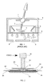
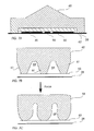
- FIG. 2 is a cross-sectional side view of a preferred embodiment of the invention.
- An articulating member 20 includes a conductive cone 22 coupled to a shaft 24 with a textured cap 26.
- An example of the cap may be found in co-pending, co-assigned U.S. Patent Application 08/315,651, filed 9/30/94, "Grip Cap for Computer Control Stick” (a copy of this application is herewith enclosed to go on the file of the present application).
- the articulating member 20 produces a user-manipulable pointing stick device, having a look and feel similar to that of a conventional TrackPoint III device.
- the shaft 24 and textured cap 26 can be replaced by a flat disk, which is pressed by the user.
- the conductive cone 22 is preferably conical in shape, but conductive members of other shapes which would suggest themselves to persons skilled in the art. Also, a non-conductive member having a conductive layer, or member, on its surface, may also be used.
- sensing electrodes 30 Underneath the conductive cone 22 is a circuit board 28, bearing a plurality of sensors, shown as sensing electrodes 30.
- the number of sensing electrodes 30 is preferably four, for detection of bi-directional movement in two dimensions. However, other suitable numbers and arrangements of sensing electrodes 30 will be understood by persons skilled in the art as being suitable for other applications.
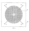
- FIG. 3 provides a top view of the board 28, showing in detail a preferred layout of the sensing electrodes 30.
- the sensing electrodes 30 are arranged as four quadrants of a circle.
- the sensing electrodes 30 are preferably etched copper clad, and electrically isolated from the conductive cone by a thin insulating layer, such as a solder mask or non-conductive tape (not shown).
- the articulating member 20 is mechanically coupled to the board 28 by means for biasing the articulating member 20 to a quiescent position, from which the articulating member 20 is movable by user manipulation.
- Gaps 33 appear between the conductive cone 22 and the electrodes 30.
- the conical shape of the conductive cone 22 facilitates the formation of the gaps 33. From the discussion which follows, it will be seen that other shapes, so long as the shapes facilitate the formation of gaps, may equivalently be used.
- the means for biasing includes a flexing member, for biasing the conductive cone 22 to a quiescent position, and for urging the conductive cone 22 back to the quiescent position if it has been moved, by externally applied force, from the quiescent position.
- the flexing member may be a tensile member such as a wire 32, which is coupled to the articulating member 20, and which runs down to the board 28, to which the wire 32 is secured.
- the apex of the cone 22 forms a point of contact between the articulating member 20 and the board 28.
- the wire 32 runs axially through the conductive cone 22, emerges from the conductive cone 22 at its apex, and runs directly through the board 28.
- the wire 32 is secured, by an electrically grounded securing rivet 34, to a conductive ground pad 36 on the bottom of the board 28.
- the apex provides a pivoting point for the conductive cone 22.
- Tension on the wire 32 provides spring action to maintain the articulating member 20 in an upright (i.e., quiescent) position when no force is exerted on the articulating member 20, and to return the articulating member 20 to the quiescent position after force, previously applied, is released.
- the wire 32 flexes, bringing a portion of the conductive cone 22 closer to one or more of the sensing electrodes 30, and another portion (on the opposite side) further away from the opposing one or more sensing electrodes 30.
- the gaps 33 change dimensions, accordingly.
- variable capacitors The conductive cone 22, the respective sensing electrodes 30, and the gaps therebetween create four variable capacitors.
- the values of the variable capacitors depend on the distance between the conductive cone 22 and the respective sensing electrodes 30, i.e., on the dimensions of the gaps 33. For instance, as the distance between the conductive cone 22 and one of the sensing electrodes 30 decreases (that is, the width of the gap 33 decreases), the capacitance between the conductive cone 22 and that one of the sensing electrodes 30 increases.
- Quadrature detection allows two degrees of freedom (i.e., the x and y components of applied force) to be measured.
- the wire 32 which is grounded to the ground pad 36, preferably also grounds the conductive cone 22.
- the conductive ground pad 36 and the grounded conductive cone 22 shield the sensing electrodes 30 from electrical noise and stray capacitance that might otherwise effect sensor readings, such as fields introduced by the human hand or other electronic circuits nearby.
- the conductive ground pad 36 and the grounded conductive cone 22 also protect the sensing electrodes 30 and their associated electronics from high voltage electric discharge.
- the outer diameter of the sensing electrodes 30 and the base (top) of the conductive cone 22 are both 10 mm, and the wire 32 is 0.61 mm diameter.
- the implementations made to date have used steel piano wire, but any other suitable material, for example other types of music wire, such as strings for stringed instruments, may also be used.
- Changes in capacitance are preferably measured by incorporating each of the sensing electrodes 30 into a respective RC oscillator.
- the resultant RC time constant, and therefore the frequency of oscillation, is a function of the capacitance between the conductive cone 22 and the respective sensing electrodes 30.
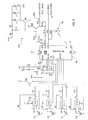
- FIG. 4 there is presented an electrical schematic of a preferred embodiment of circuitry for utilizing the capacitances provided by the apparatus of the invention.
- the four sensing electrodes 30 of FIGs. 2 and 3 are represented in FIG. 4 as variable capacitors Ca, Cb, Cc, and Cd.
- the ground of each of the sensing electrodes 30 is preferably that of the conductive cone 22.
- variable capacitance values are used in combination with feedback resistors R8, R3, R4, and R9, and with NAND gates U1/A, U1/B, U1/C, and Ul/D (preferably provided in a 74HC132 Schmitt-triggered input integrated circuit; pinouts shown), to create four oscillators and a sensor selector.
- Each NAND gate has two inputs, one serving as an oscillator input (e.g., the pin 2 input of the U1/A gate of the 74HC132 device, which is shown as coupled to the sensing electrode 30 represented as the capacitor Ca), and the other (e.g., the pin 1 input of the U1/A gate) serving as a selection control line.
- an oscillator input e.g., the pin 2 input of the U1/A gate of the 74HC132 device, which is shown as coupled to the sensing electrode 30 represented as the capacitor Ca
- the other e.g., the pin 1 input of the U1/A gate
- the outputs of the four NAND gate oscillators are ORed together by a transistor Q5 (e.g., a 2N3906 PNP bipolar transistor). Suitable coupling, such as resistors R7, R2, R5, and R10, are provided.
- the output of the transistor Q5 (the collector of the transistor Q5) thus produces a signal which oscillates at a frequency related to the capacitance of the selected sensing electrode 30.
- the frequency of oscillation of the ORed result is counted by a microcontroller 38, preferably a PIC16C58A integrated circuit (pinouts shown).
- the microcontroller 38 runs calibration code that normalizes the gain of each of the four illustrated sensor circuits, producing a normalized force signal, compensating for component, mechanical, and manufacturing tolerances.
- the microcontroller 38 Since the sensor is to emulate a conventional mouse pointing device which has velocity as an output, the microcontroller 38 performs a non-linear transformation on the normalized force signals to produce a velocity signal.
- the microcontroller 38 formats the velocity signal into conventional mouse protocol such as "Microsoft Mouse", and sends the velocity signal out through an output such as a serial port (RS-232 or PS/2) 39, or an infrared (IR) port 37.
- IR infrared
- wired generally shown as 39
- a high current transistor Q6 e.g., an FZT869 switches high-brightness infrared light emitting diodes 37A (e.g., HSDL4220) for infrared communication.
- a low current switching transistor Q4 e.g., 2N3906 implements a serial RS-232 communication interface 39A.
- the microcontroller 38 selects one of the NAND gate oscillators, and counts the number of oscillations for a fixed period of time. The final count is proportional to the sensor frequency 80, and is used to determine the applied force. This will be explained in greater detail in the section "DYNAMIC CALIBRATION", appearing below.
- the feedback resistors R8, R3, R4, and R9 are chosen for the maximum oscillation frequency countable by the microcontroller 38, typically less than 1 MHZ. Each sensor channel is integrated (oscillation counted) for 2.5 msec, resulting in a 100 Hz update rate of force direction and magnitude applied to the conductive cone 22.
- the implementation provides a 10 bit resolution sensor measurement signal with a full-scale change in excess of 25%.
- the current cost for large quantities (e.g., more than 100,000) of the Schmitt-trigger NAND circuits, and of the microcontroller 38, is approximately $0.20 and $1.00 per piece, respectively, making it possible to construct a capacitive sensor with acquisition and processing hardware for less than $3.
- These figures compare quite favourably with previous implementations of pointing devices, such as that of co-pending patent application 08/181,648.
- the other conventional devices such as that shown in the Hughes patent, would evidently be much more costly to produce, even if they were suitable for in-keyboard applications.
- devices according to the invention are easier and less expensive to fabricate, using a conventional printed circuit board process, and are more compact because they have a lower profile.
- Attaching the articulating member 20 to the two dimensional surface (such as the circuit board 28) which includes the sensing electrodes 30, as shown in FIGs. 2 and 3, decreases material and assembly cost, and makes for a more compact device.
- the prior art Hughes patent teaches a device whose quiescent position places no conductor in the vicinity of the sensing electrodes. In that quiescent position, each of the capacitances of each sensing electrode is negligible, due to the relatively great distance.
- the conductive cone 22 is in the vicinity of the sensing electrodes 30.
- the capacitances of the sensing electrodes 30, in the quiescent position have finite, measurable, and useable values.
- quiescent capacitance values need not necessarily be equal or even substantially equal.
- transfer functions including scaling, are employed to utilize the raw information obtained from the capacitance values.
- sensing electrodes such as the exemplary four two-dimensional sensing electrodes 30, are disposed on a substrate in continuous close proximity to the articulating member 20, this necessitates calibration unforeseen by Hughes.
- Appropriate calibration is described below to create an accurate and sensitive force sensor from low-cost, low tolerance parts, using low-cost construction techniques. Measuring small forces accurately near the quiescent position is vital for pixel manipulation in computer applications. Thus, even taking into account the manufacturing time and costs associated with the calibration, the resultant sensor according to the invention compares favourably with conventional devices.
- the capacitances are calibrated, preferably by using an adaptive algorithm in which the maximum, minimum, and quiescent channel readings are stored, and in which a gain factor is calculated from these values.
- Independent RC oscillators are used, each sensing electrode 30 contributing substantially to the capacitance of one RC oscillator. Therefore, advantageously accurate values are obtained.
- a switch is provided, along with the sensing apparatus described above.
- the switch is preferably monostable, having a stable position when the articulating member 20 is not being manipulated, and having a second position, which the switch enters when the articulating member 20 is manipulated in a suitable fashion, and remaining in the second position only until the user ceases manipulating the articulating member 20.
- the switch is provided for either (or both) of two purposes.
- the first purpose is related to the use of mechanical switches, on conventional mice, to select objects (one click), to launch programs (two clicks), and to select and drag an icon or other object (press to select object, hold while moving object).
- a switch as provided in the embodiment to be described provides for that same functionality.
- the second purpose of the switch of the present embodiment has to do with power savings.
- the sensor electronics are preferably powered only when the sensor is actually being used by an operator. Switching is provided, in accordance with the invention, to achieve this power savings.
- a timer is used to shut off the sensor electronics after a period of inactivity.
- the microcontroller 38 is preferably programmed to perform the timing and switching function.
- the switch is used to indicate user activity.
- a polling scheme is used.
- the sensor electronics are periodically energized, for example every second, to check for activity.
- Touching is preferably detected by means of a threshold pressure, such as 10 grams. Closing the switch sends a "wake up" signal to the microcontroller 38.
- the user applies a vertical (z axis) force to the pointing stick, achieved through the embodiments described below. (Note, by the way, that similar user manipulation of the device according to the invention may also select and drag an object.)
- a mechanical switch 50 is placed underneath the sensor, offset from the articulating member 20, using the circuit board 28 as a lever arm, and having a fulcrum 52 disposed across from the switch 50.
- the location of the fulcrum 52, the member 20, and the switch 50 may be positioned, relative to each other, in any suitable arrangement to obtain the desired activation force and displacement.
- the mechanical switch 50 is preferably a metal dome type, to give tactile feedback (an impulse "click") when engaged, and hysteresis when disengaged.
- the switch activation force should preferably be greater than the force used to move a cursor, to prevent accidental switch engagement when translation of the cursor was intended.
- a typical switch activation force is 350-400 grams with 50 grams of hysteresis.
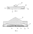
- an articulating member 59 is used in place of the conductive cone 22.
- the upper surface of the member 59 has a shape and texture suitable for good contact with a user's fingertip.
- the member 59 is made of molded rubber. However, other materials, having properties suitable for the purpose to be described herein, may be used.
- the lower surface of the member 59, which faces the sensors 30, has disposed thereon a conductive layer, such as a layer of conductive rubber 58.
- the conductive rubber layer 58 preferably has a shallow conical shape, to provide a variable gap between the conductive rubber 58 and the sensing electrodes 30. As shown in FIG. 6, the apex of the cone-shaped conductive rubber 58 is slightly closer to the board 28 than the perimeter of the conductive rubber 58 is. This arrangement lends itself well to calibration (described below).
- the member 59 preferably has low resilience. Manipulation by the user's fingertip causes the member 59, as a substantially rigid body, to be displaced. Likewise, the conductive layer 58 is displaced, so as to cause changes in capacitance, similarly to the changes in capacitance described above for the previous embodiment of the invention.
- a force applied to the top of the articulating member 59 in the x-y plane causes a section of the conductive rubber 58 to move closer to the sensing electrodes 30. This closer proximity causes a differential change in capacitance among the four sensing electrodes 30.
- a force applied to the apex of the articulating member 59 in the z-axis causes the conductive rubber 58 to move closer to all four sensing electrodes 30. This motion causes a common mode change in capacitance among the four sensing electrodes 30.
- the microcontroller 38 of FIG. 4 processes the four sensing electrode signals so as to identify this z-axis force. A preferred method of doing so is to sum the calibrated outputs of each sensor channel. This calculation will be discussed in more detail in the section describing calibration (below).
- a switching state can be deduced from the identified z-axis force by several techniques.
- a simple method is to set an absolute threshold that must be exceeded to be interpreted as a change in switch state.
- Hysteresis can be added to prevent switch "chatter" when the z-axis force, applied to the apex of the articulating member 59, centers around the switching threshold.
- Another method is to compare a derivative of the z-axis force with a threshold value.
- This method can employ the first derivative representing velocity, or the second derivative representing acceleration.
- FIG. 6 Another aspect of the preferred structure of FIG. 6 provides tactile feedback.
- a thin wall 57 is shown, running around a perimeter of the articulating member 59.
- the thin wall 57 is shown, in the cross-section of FIG. 6, at either outer end of the articulating member 59.
- the shape of the wall 57 preferably follows the shape of the perimeter of the articulating member 59. Where the member 59 is cone-shaped, the wall 57 is annular in shape, similar to that commonly provided in rubber dome switches.
- this wall 57 provides a "breakaway" force. That is, an abrupt tactile sensation, responsive to fingertip force of a suitable magnitude, is caused by the collapse of the thin wall 57 under the pressure from the user's fingertip.
- the breakaway force provides physical tactile feedback to the user when the articulating member 59 is pressed in the z-axis with sufficient activation force (e.g. 30 grams).
- sufficient activation force e.g. 30 grams.
- the circuitry of FIG. 4 detects the activation force as a dramatic change in the sum of all sensor channels by the microcontroller 38.
- a switch sensing electrode 56 is provided on the circuit board. (FIG. 6 shows the electrode 56 centered below the articulating member 59, but other suitable locations may also be used.)
- the collapse of the thin wall 57 allows the conductive rubber 58 to make physical resistive contact with the switch sensing electrode 56, closing an electrical circuit and generating an electrical signal.
- the electric signal can be used to wake up the microcontroller 38 from its sleeping mode, or to function as a mouse switch (e.g. to select an object) when the microcontroller 38 is operating.
- the embodiment illustrated in FIG 6 may be built using otherwise conventional rubber dome switch materials and otherwise conventional manufacturing techniques, minimizing cost and complexity.
- the articulating member 59 and the conductive rubber 58 can be part of a one piece multiple switch assembly, such as those used on television remote controls.
- Some alternative methods of manufacture include coating the side of the articulating member 59 facing the circuit board 28 with a conductive material, or impregnating the entire articulating member 59 with a conductive filler, such as carbon.
- FIGs. 7A, 7B, and 7C Another preferred embodiment of the apparatus of the invention is shown in FIGs. 7A, 7B, and 7C, a general cross-sectional view and two detailed cross-sectional views, respectively.
- an articulating member 60 is disposed on the circuit board 28, the latter having the sensing electrodes 30 and the switch sensing electrode 56 disposed thereon, as per previously discussed embodiments.
- the conductive rubber layer 58 of FIG. 6 is replaced by a textured conductive rubber 62, attached as before to the inside (lower) surface of the articulating member 60.
- a thin insulating layer 63 (e.g., solder mask or non-conducting tape) is preferably provided, to prevent resistive contact between the conductive rubber 62 and the sensing electrodes 30.
- FIGs. 7B and 7C are views of surface detail of the textured conductive rubber 62. As shown in FIG. 7B, the surface includes alternating projections 61, preferably in the form of teeth, and voids 64.
- the conductive rubber 62 compresses against the circuit board 28. This causes the teeth 61, made of resilient, conductive rubber material, to deform and expand sideways, filling the voids 64.
- the deformation of the conductive material brings more of the conductive material closer to the sensing electrodes 30. This added proximity decreases the capacitance between the conductive rubber 62 and the sensing electrodes 30.
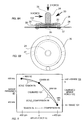
- FIGs. 8A and 8B A fourth embodiment of the invention is shown in a cross-sectional view in FIGs. 8A and 8B.
- the conductive cone 22 is suspended above the sensing electrodes 30 by the articulating member 20.
- the articulating member 20 includes a shaft 24, preferably oriented along a vertical axis, and having a top 26 for user fingertip manipulation.
- an immobile support member 35 is coupled to the shaft 24 by a flexible member 132.
- the flexible member 132 has a convex shape similar to that of a collapsible dome, so that user manipulation can cause a collapse of the flexible member 132, the collapse providing tactile feedback.
- the support member 35 is preferably annular, as shown in FIG. 8B, and preferably has a plurality of anchoring posts 37, which are inserted into apertures in the board 28, to anchor the support member 35 in place.
- the cone 22 is coupled to the bottom of the shaft 24, to move therewith, responsive to user fingertip manipulation. As before, narrow gaps 33 exist between the surface of the cone 22 and the sensors 30.
- the gaps 33 between the entire conductive cone 22 and the electrodes 30 (typically 0.25 mm (0.01 inch) at zero force), in combination with the articulating member 20, allow three dimensional movement of the conductive cone 22 by forces applied to the shaft 24.
- the flexible member 132 provides the restoring force, and is preferably shaped as an arch, to distribute the stress and keep the stress well within the elastic limit of the material. The thickness of the flexible member 132, the length of the shaft 24, and the modulus of the material contribute to the sensitivity and maximum force that can be measured.
- the present embodiment of the invention offers advantageously simple construction and installation.
- the anchoring posts 37 are preferably made of a material, such as nylon, which can be ultrasonically welded to the circuit board 28.
- the conductive cone 22 and articulating member 20 are preferably injection molded parts, press-fit together.
- the cap 26 preferably has texturing, such as protrusions molded into the part (preferably less than 0.13 mm (0.005 inch) in width and 0.25 mm (0.01 inch) in length), to catch the skin of the finger, providing a "grippy" high friction top.
- the conductive cone 22 is made of conductive plastic (for example, 50% carbon fiber filled nylon, part number #J-1/CF/50/EG from DSM Engineering Plastics, Evansville, IN, USA), and the articulating member 20 is made of non-conductive nylon.
- inactive electrodes 30 provide enough proximal ground reference to the conductive cone 22, eliminating the need for an electrical connection to the conductive cone 22.
- the conductive cone 22, the underside of the flexible member 132, and surface of the anchor posts 37 are made of conductive material (for example, carbon filled polymer thick film conductive paint, part # 7101, Dupont Electronics, Research Triangle Park, NC), to provide a low impedance (e.g. under 1,000 ohms) to the conductive ground pad 36, increasing the dynamic range, electronic shielding, and noise immunity of the device.
- the embodiment of FIGs. 8A and 8B hermetically seals the electrodes 30 from the environment, providing a barrier from moisture (humidity) and other contaminating matter.
- the annular rim 35 completely seals the electrodes 30 from the environment.
- An algorithm is used in conjunction with the above-described apparatus to compensate for component, manufacturing, thermal, humidity, mechanical, and supply voltage variability.
- the algorithm runs during operation of a system and may be implemented in program code, to be executed by the microcontroller 38 or by a system CPU (not shown).
- FIG. 9 is a graph, showing sensor frequency 80, such as that produced by the microcontroller 38 of FIG. 4, versus force 82 applied to a device by a user's fingertip.
- the graph pertains to a capacitive link between an articulating member and one of the sensors (see any of the above-discussed embodiments). It will be understood that, for a device employing a plurality of sensors, such as those shown in FIG. 3, there will be a separate such curve for each of the sensors.
- the applied force (the abscissa of the graph) has a neutral, central point at which zero force is applied. Deviations from the zero point, in the horizontal direction, reflect either tension 86 or compression 83, caused by opposite-direction forces applied to a given one of the sensors 30.
- the frequency 80 of a sensor channel decreases as the conductive cone 22 is forced towards a sensing electrode 30 (COMPRESSION 82).
- the conductive cone 22 is pulled away from a sensing electrode 30 (TENSION 86)
- the capacitance is decreased, and hence the frequency increases.
- the domain of force values is bounded by MAX and MIN applied force values, shown in this example as being plus and minus 400 grams.
- the sensor frequency output is a force-to-frequency curve, which, for the present example, is marked as RAW 88, the "RAW” referring to the fact that the curve has not yet been subjected to the algorithm (discussed below).
- the curve 88 has three points, CENTER 90, MAX 92, and MIN 94, which define the sensor frequencies for the zero, MAX, and MIN applied force values.
- the force-to-frequency curve 88 runs between these points.
- the points i.e., their coordinates according to the abscissa and ordinate, are stored, as reference values, for each sensor channel.
- the shape of the force-to-frequency curve 88 depends on several factors, including the geometry of the articulating member 20 and of the sensing electrodes 30.
- the curve need not be linear, and it is contemplated that for most implementations of the above-discussed apparatus, it will not be so.
- the curve is non-linear.
- the calibration algorithm acts to modify, preferably to linearize or piecewise linearize, the force-to-frequency curve 88.
- the algorithm converts the curve 88, given in terms of the ordinate scale on the left side of the graph, into a calibrated sensor force 102, given in terms of another ordinate scale on the right side of the graph.
- the range of the calibrated sensor force 102 runs between a minimum 104, labeled - RANGE, and a maximum 106, labelled + RANGE 106.
- the minimum 104 and the maximum 106 are shown having normalized values -64 and +63, respectively.
- the preferred calibration algorithm approximates the non-linear curve RAW 88 as two linear segments, running between the points 90, 92, and 94. These segments have slopes shown as SCALE_TENSION 96 and SCALE_COMPRESSION 98. The slopes are calculated between the maximum 92, the minimum 94, and the center 90 points, as shown.
- the MAX 92 and MIN 94 reference values are dynamically updated every time a sensor channel is read. This typically happens 100 times per second.
- the CENTER 90 is updated when the articulating member 20 is undisturbed, that is, when no external force is applied.
- an undisturbed state is declared when the changes in the calibrated sensor outputs 102 of all of the sensor channels remain within a minimum movement tolerance for a fixed period of time, for example, when the changes all remain within three calibrated units, according to the sensor output 102 scale, for three seconds.
- the calibrated sensor output (given in terms of the calibrated sensor force scale 102) are obtained for each sensor channel, the calibrated values are subjected to a force-to-velocity transfer function.
- the calibration reference values (the sloped line segments SCALE_TENSION 96 and SCALE_COMPRESSION 98, and the points MAX 92, MIN 94, and CENTER 90) are measured and calculated dynamically.
- the calibration reference values are stored in EEPROM or ROM during manufacture.
- An implementation of the dynamic calibration algorithm, transfer function, and additional code to perform serial mouse protocol and infrared wireless modulation occupies less that 2K of ROM and 72 bytes of RAM in the PIC16C58 microcontroller 38.
- the device described herein needs to be able to operate reliably on battery power.
- the frequency of the NAND RC oscillators is dependent on supply voltage.
- the voltage of alkaline batteries decreases as energy is drawn.
- a preferred embodiment uses a zener diode to stabilize the supply voltage to the NAND circuit.
- Another embodiment periodically decrements the MAX 92 and MIN 94 value, by a fixed increment, to track the decrease in oscillation frequency.
- the non-linearity of the force-to-frequency curve (the curve shown in FIG. 9) of the devices, such as that of FIG. 2, can be minimized by reducing the range of deflection of the conductive cone 22, preferably by increasing the stiffness or diameter of the wire 34.
- a smaller deflection range spans a smaller section of the RAW 88 curve, which is more closely approximated by a linear fit.
- the accuracy of the piece-wise linearization technique can further be enhanced by increasing the number of calibration samples.
- the shape of the RAW 88 curve is linearized by the particular shape of the sensing electrodes 30.
- the sensing electrodes 30 are concave-tapered to decrease the slope (sensitivity) of the frequency output 88 around the quiescent (zero force) region.
- the sensing electrodes 30 are convex-tapered to decrease the slope of the frequency output 88 around the MAX 92 and MIN 94 region. Decreasing the area of the sensing electrodes 30 decreases the dynamic range of the sensor 21. If the dynamic range, for a given configuration of the electrodes 30, is not adequate for a particular application, then the dynamic range can be recovered by increasing the diameter of the cone 22.
Applications Claiming Priority (2)
| Application Number | Priority Date | Filing Date | Title |
|---|---|---|---|
| US08/735,482 US6184865B1 (en) | 1996-10-23 | 1996-10-23 | Capacitive pointing stick apparatus for symbol manipulation in a graphical user interface |
| US735482 | 1996-10-23 |
Publications (3)
| Publication Number | Publication Date |
|---|---|
| EP0838776A2 true EP0838776A2 (de) | 1998-04-29 |
| EP0838776A3 EP0838776A3 (de) | 2003-10-29 |
| EP0838776B1 EP0838776B1 (de) | 2006-08-30 |
Family
ID=24956005
Family Applications (1)
| Application Number | Title | Priority Date | Filing Date |
|---|---|---|---|
| EP97308417A Expired - Lifetime EP0838776B1 (de) | 1996-10-23 | 1997-10-22 | Benutzereingabeabtastvorrichtung |
Country Status (3)
| Country | Link |
|---|---|
| US (2) | US6184865B1 (de) |
| EP (1) | EP0838776B1 (de) |
| DE (1) | DE69736584T2 (de) |
Cited By (8)
| Publication number | Priority date | Publication date | Assignee | Title |
|---|---|---|---|---|
| EP1136939A2 (de) * | 2000-03-14 | 2001-09-26 | Alps Electric Co., Ltd. | Auf Kapazitätsänderung basierte Eingabevorrichtung und Erfassungseinrichtung |
| EP1164698A2 (de) * | 2000-06-16 | 2001-12-19 | Alps Electric Co., Ltd. | Eingabegerät |
| WO2002017222A2 (en) * | 2000-08-23 | 2002-02-28 | International Business Machines Corporation | Digital pen |
| CN100380297C (zh) * | 2003-11-24 | 2008-04-09 | 阿瓦戈科技Ecbuip(新加坡)股份有限公司 | 自索引计算机指点设备的模块化组件 |
| EP2174360A1 (de) * | 2007-06-29 | 2010-04-14 | Artificial Muscle, Inc. | Wandler mit elektroaktivem polymer für anwendungen der sensorischen rückmeldung |
| CN104181907A (zh) * | 2014-08-18 | 2014-12-03 | 如冈自动化控制技术(上海)有限公司 | 非接触式金属缝隙及表面的数控跟踪器和跟踪方法 |
| CN107728928A (zh) * | 2017-11-24 | 2018-02-23 | 华勤通讯技术有限公司 | 一种适用于笔记本电脑的指针控制装置 |
| IT202000022744A1 (it) * | 2020-09-25 | 2022-03-25 | Cnh Ind Italia Spa | Metodo e dispositivo di controllo di attuazione di una pala meccanica di un veicolo da lavoro |
Families Citing this family (60)
| Publication number | Priority date | Publication date | Assignee | Title |
|---|---|---|---|---|
| US6184865B1 (en) * | 1996-10-23 | 2001-02-06 | International Business Machines Corporation | Capacitive pointing stick apparatus for symbol manipulation in a graphical user interface |
| US6184866B1 (en) * | 1997-09-29 | 2001-02-06 | Varatouch Technology Incorporated | Pointing device |
| JP2000047811A (ja) * | 1998-07-27 | 2000-02-18 | Alps Electric Co Ltd | 入力装置 |
| US7289107B1 (en) * | 1999-03-12 | 2007-10-30 | Varatouch Technology, Inc. | Auto-calibration of pointing devices used in a computer user interface |
| JP2000305709A (ja) * | 1999-04-26 | 2000-11-02 | Alps Electric Co Ltd | 電子機器 |
| TW430098U (en) * | 1999-05-04 | 2001-04-11 | Acer Peripherals Inc | Sensitive pointing device with ability of being miniatured |
| US6480183B1 (en) * | 1999-07-23 | 2002-11-12 | Logitech Europe S.A. | Digital joystick using capacitive sensor |
| TW449713B (en) * | 1999-08-27 | 2001-08-11 | Darfon Electronics Corp | A pointing stick device that enables to increase the sensitivity of vertical direction |
| JP3421006B2 (ja) * | 1999-09-11 | 2003-06-30 | 株式会社ソニー・コンピュータエンタテインメント | 操作装置 |
| JP2001221700A (ja) * | 2000-02-08 | 2001-08-17 | Nitta Ind Corp | 静電容量式センサ |
| US7602376B1 (en) * | 2000-02-22 | 2009-10-13 | P.I. Engineering, Inc. | Moving dielectric, capacitive position sensor configurations |
| US7298352B2 (en) * | 2000-06-28 | 2007-11-20 | Lg.Philips Lcd Co., Ltd. | Apparatus and method for correcting gamma voltage and video data in liquid crystal display |
| JP3903731B2 (ja) * | 2000-08-03 | 2007-04-11 | 松下電器産業株式会社 | 多方向入力装置およびこれを用いた電子機器 |
| US8199114B1 (en) * | 2000-09-26 | 2012-06-12 | Denny Jaeger | Touch sensor control devices |
| JP2002328775A (ja) * | 2001-04-27 | 2002-11-15 | Alps Electric Co Ltd | 座標入力装置 |
| JP2002340699A (ja) * | 2001-05-21 | 2002-11-27 | Mitsumi Electric Co Ltd | 静電容量センサー |
| US20030001874A1 (en) * | 2001-06-27 | 2003-01-02 | International Business Machines Corporation | Method and apparatus for computer input using the skin as sensory feedback |
| US6892597B2 (en) | 2001-07-27 | 2005-05-17 | Pelco | Joystick |
| JP3971907B2 (ja) * | 2001-09-17 | 2007-09-05 | アルプス電気株式会社 | 座標入力装置及び電子機器 |
| WO2003042807A1 (en) * | 2001-11-12 | 2003-05-22 | Ken Alvin Jenssen | Control device (mouse) for computer |
| EP1351121A3 (de) * | 2002-03-26 | 2009-10-21 | Polymatech Co., Ltd. | Eingabevorrichtung |
| US6888076B2 (en) * | 2002-11-21 | 2005-05-03 | P.I. Engineering, Inc. | Substantially rigid capacitive joystick designs |
| JP2004219311A (ja) * | 2003-01-16 | 2004-08-05 | Omron Corp | 静電容量センサ及び開閉体挟み込み検知装置 |
| US7199783B2 (en) * | 2003-02-07 | 2007-04-03 | Avago Technologies Ecbu Ip (Singapore) Pte. Ltd. | Wake-up detection method and apparatus embodying the same |
| WO2004099935A2 (en) * | 2003-05-05 | 2004-11-18 | Tapwave, Inc. | System and method for generating an analog signal in a hand-held computing device |
| US7684754B2 (en) * | 2003-06-03 | 2010-03-23 | Microsoft Corporation | Capacitive bonding of devices |
| US7822983B2 (en) | 2003-08-21 | 2010-10-26 | Microsoft Corporation | Physical device bonding |
| US8350345B2 (en) * | 2003-12-29 | 2013-01-08 | Vladimir Vaganov | Three-dimensional input control device |
| US20060125781A1 (en) * | 2004-12-15 | 2006-06-15 | Sachs Todd S | Sliding structure location on a pointing device corrected for non-linearity of measured differential |
| EP1677177A1 (de) * | 2004-12-29 | 2006-07-05 | STMicroelectronics S.r.l. | Zeigergerät für ein Rechnersystem mit automatischer Erkennung des Bewegungszustandes, und relatives Steuerungsverfahren |
| US20060146018A1 (en) * | 2005-01-04 | 2006-07-06 | Arneson Theodore R | Joystick with tactile feedback |
| US7337671B2 (en) | 2005-06-03 | 2008-03-04 | Georgia Tech Research Corp. | Capacitive microaccelerometers and fabrication methods |
| JP4700432B2 (ja) * | 2005-07-29 | 2011-06-15 | 本田技研工業株式会社 | 車両用操作装置 |
| US7578189B1 (en) * | 2006-05-10 | 2009-08-25 | Qualtre, Inc. | Three-axis accelerometers |
| US20080062129A1 (en) * | 2006-09-12 | 2008-03-13 | Monster, Llc | Remote Controller Having Concentric Cursor Control Islands |
| US8902173B2 (en) * | 2006-09-29 | 2014-12-02 | Cypress Semiconductor Corporation | Pointing device using capacitance sensor |
| KR100803607B1 (ko) * | 2006-10-19 | 2008-02-15 | 삼성전자주식회사 | 터치 센서 유닛 및 터치 센서 유닛의 민감도 조절 방법 |
| US7961945B2 (en) * | 2007-02-13 | 2011-06-14 | Technische Universität München | System and method for on-the-fly segmentations for image deformations |
| US7451664B1 (en) * | 2007-09-28 | 2008-11-18 | Honeywell Interntional Inc. | User interface force sensor system |
| CA2700469C (en) * | 2007-10-11 | 2016-11-15 | Cube Investments Limited | Capacitive probes and sensors, and applications therefor, and multimode wireless devices |
| JP4523049B2 (ja) * | 2008-04-25 | 2010-08-11 | Smk株式会社 | 指示入力装置 |
| US9041650B2 (en) * | 2008-09-18 | 2015-05-26 | Apple Inc. | Using measurement of lateral force for a tracking input device |
| US9639187B2 (en) | 2008-09-22 | 2017-05-02 | Apple Inc. | Using vibration to determine the motion of an input device |
| JP5483430B2 (ja) * | 2010-03-31 | 2014-05-07 | 株式会社ワコム | 可変容量コンデンサおよび位置指示器 |
| US8624759B2 (en) | 2010-05-19 | 2014-01-07 | Nokia Corporation | Apparatus and method for an actuator in an electronic device |
| US9128508B2 (en) * | 2010-06-15 | 2015-09-08 | Razer (Asia-Pacific) Pte Ltd. | Module for controlling a force required to actuate an electromechanical actuator |
| DE102011079174A1 (de) * | 2011-07-14 | 2013-01-17 | Zf Friedrichshafen Ag | Positionserfassungsvorrichtung |
| US8982094B2 (en) | 2012-12-28 | 2015-03-17 | Shenzhen Huiding Technology Co., Ltd. | Device-to-device communications based on capacitive sensing and coupling via human body or direct device-to-device coupling |
| US9449768B2 (en) * | 2013-01-04 | 2016-09-20 | Synaptics Incorporated | Stabilization techniques for key assemblies and keyboards |
| JP5824487B2 (ja) * | 2013-08-09 | 2015-11-25 | レノボ・シンガポール・プライベート・リミテッド | ポインティング・デバイス、キーボード・アセンブリおよび携帯式コンピュータ。 |
| US9925456B1 (en) | 2014-04-24 | 2018-03-27 | Hasbro, Inc. | Single manipulatable physical and virtual game assembly |
| EP3161597A1 (de) * | 2014-06-24 | 2017-05-03 | Google, Inc. | Computerisierte systeme und verfahren zum schichten von inhalt in einer benutzerschnittstelle |
| CN105224103B (zh) * | 2014-07-04 | 2018-05-01 | 原相科技股份有限公司 | 电容式摇杆装置 |
| TWI544371B (zh) * | 2014-07-04 | 2016-08-01 | 原相科技股份有限公司 | 電容式搖桿裝置 |
| US9814986B2 (en) | 2014-07-30 | 2017-11-14 | Hasbro, Inc. | Multi sourced point accumulation interactive game |
| US10444862B2 (en) | 2014-08-22 | 2019-10-15 | Synaptics Incorporated | Low-profile capacitive pointing stick |
| US9947493B2 (en) | 2014-10-24 | 2018-04-17 | Synaptics Incorporated | Magnetically biased retracting key assembly and keyboard |
| US9354720B1 (en) | 2014-12-23 | 2016-05-31 | Synaptics Incorporated | Low-profile capacitive pointing stick |
| US9898095B2 (en) | 2015-06-29 | 2018-02-20 | Synaptics Incorporated | Low-profile capacitive pointing stick |
| US10088915B2 (en) | 2016-07-01 | 2018-10-02 | Deere & Company | Method and system with sensors for sensing hand or finger positions for adjustable control |
Citations (3)
| Publication number | Priority date | Publication date | Assignee | Title |
|---|---|---|---|---|
| US4305007A (en) | 1979-08-22 | 1981-12-08 | Gerald N. Stan | Electronic two directional control apparatus |
| EP0663648A2 (de) | 1994-01-14 | 1995-07-19 | International Business Machines Corporation | Kraftwandler |
| JPH08115160A (ja) | 1994-09-30 | 1996-05-07 | Internatl Business Mach Corp <Ibm> | コンピュータの制御スティック用グリップ・キャップ及びその作製方法 |
Family Cites Families (46)
| Publication number | Priority date | Publication date | Assignee | Title |
|---|---|---|---|---|
| US3270260A (en) | 1963-11-18 | 1966-08-30 | Measurement Systems Inc | Stick-operated diaphragm control |
| US3447766A (en) | 1967-02-14 | 1969-06-03 | Bendix Corp | Control stick with solid state sensors |
| JPS5015669A (de) | 1973-06-12 | 1975-02-19 | ||
| US4103252A (en) | 1976-11-26 | 1978-07-25 | Xerox Corporation | Capacitive touch-activated transducer system including a plurality of oscillators |
| US4264903A (en) | 1978-06-12 | 1981-04-28 | General Electric Company | Capacitive touch control and display |
| US4311980A (en) | 1978-10-12 | 1982-01-19 | Fabrica Italiana Magneti Marelli, S.P.A. | Device for pressure measurement using a resistor strain gauge |
| DE2931489B1 (de) | 1979-08-03 | 1980-10-16 | Jungheinrich Kg | Steuerhebelschalter |
| US4493219A (en) | 1982-08-02 | 1985-01-15 | Illinois Tool Works, Inc. | Force transducer |
| US4536746A (en) | 1982-09-30 | 1985-08-20 | The Mercado Venture | Transducer for converting three dimensional mechanical input displacements into a corresponding electrical output signal |
| JPS59155735A (ja) | 1983-02-24 | 1984-09-04 | Aisin Seiki Co Ltd | 接触圧センサ− |
| US4550316A (en) | 1983-04-29 | 1985-10-29 | Display Interface Corp. | Stylus mouse |
| US4755634A (en) | 1983-07-12 | 1988-07-05 | Peptek, Incorporated | Conductive electrode arrays and arrays of resistive elements for use in touch panels and for producing electric fields |
| US4670743A (en) | 1985-01-31 | 1987-06-02 | General Instrument Corporation | Keyboard cursor controller |
| US4872672A (en) | 1985-09-09 | 1989-10-10 | Microcube Corporation | Proportional control with a joystick device for inputting computer variables |
| JPS62153538A (ja) | 1985-12-27 | 1987-07-08 | Toyota Motor Corp | 内燃機関の燃料供給制御装置 |
| IT1187900B (it) | 1986-02-10 | 1987-12-23 | Marelli Autronica | Dispositivo sensore di pressione |
| US4694279A (en) | 1986-10-17 | 1987-09-15 | University Of Pittsburgh | Vector electronic control device |
| US4719538A (en) | 1986-12-02 | 1988-01-12 | Cox John D | Force responsive capacitive transducer |
| US4811491A (en) | 1987-09-04 | 1989-03-14 | Etak, Inc. | Two-axis differential capacitance inclinometer |
| US4932265A (en) | 1987-12-11 | 1990-06-12 | The Babcock & Wilcox Company | Pressure transducer using thick film resistor |
| GB8808614D0 (en) * | 1988-04-12 | 1988-05-11 | Renishaw Plc | Displacement-responsive devices with capacitive transducers |
| FR2632793B1 (fr) | 1988-06-08 | 1994-04-15 | Jaeger | Touche perfectionnee exploitant les proprietes d'un cristal liquide |
| US5012231A (en) * | 1988-12-20 | 1991-04-30 | Golemics, Inc. | Method and apparatus for cursor motion having variable response |
| JPH02184912A (ja) | 1989-01-11 | 1990-07-19 | Nec Corp | パルス信号発生装置 |
| GB2234629B (en) | 1989-06-28 | 1993-01-27 | Ivor John Martin Fehr | Improvements relating to strain gauges |
| DE4000326C2 (de) | 1990-01-08 | 1995-12-14 | Mannesmann Ag | Drucksensor |
| US5241308A (en) | 1990-02-22 | 1993-08-31 | Paragon Systems, Inc. | Force sensitive touch panel |
| WO1991017415A1 (de) | 1990-05-07 | 1991-11-14 | Robert Bosch Gmbh | Verfahren und vorrichtung zum herstellen eines sensors zum bestimmen von druckkräften |
| US5160918A (en) | 1990-07-10 | 1992-11-03 | Orvitek, Inc. | Joystick controller employing hall-effect sensors |
| US5407285A (en) | 1990-07-24 | 1995-04-18 | Franz; Patrick J. | Pointing stick in a computer keyboard for cursor control |
| WO1992009996A1 (en) | 1990-11-29 | 1992-06-11 | Lexmark International, Inc. | Analog input device located in the primary typing area of a keyboard |
| US5140313A (en) | 1991-01-17 | 1992-08-18 | O Che Wen | Joy stick assembly |
| WO1992018927A1 (en) | 1991-04-19 | 1992-10-29 | Home Row, Inc. | Cursor tracking |
| US5319980A (en) | 1991-06-07 | 1994-06-14 | Maclean-Fogg Company | Board construction for resistive strain gauge pressure sensors |
| US5224384A (en) | 1991-06-07 | 1993-07-06 | Maclean-Fogg Company | Resistive strain gauge pressure sensor |
| DE69215820T2 (de) | 1991-10-01 | 1997-07-03 | Gen Electric | Auto-Kalibrierung eines kraftempfindlichen Tastensystems, deren Wandler einer Parameterdrift unterworfen ist |
| US5847694A (en) * | 1991-12-05 | 1998-12-08 | Tv Interactive Data Corporation | Apparatus for generating a signal indicative of the position of a movable element in the apparatus |
| US5237753A (en) | 1992-05-18 | 1993-08-24 | Lucas Sensing Systems, Inc. | Capacitive gravity sensor and inclinometer |
| US5421694A (en) | 1993-05-20 | 1995-06-06 | Caterpillar Inc. | Non-contacting joystick |
| US5440237A (en) * | 1993-06-01 | 1995-08-08 | Incontrol Solutions, Inc. | Electronic force sensing with sensor normalization |
| JPH07281823A (ja) | 1994-04-15 | 1995-10-27 | Hosiden Corp | 座標入力装置 |
| JP2844308B2 (ja) | 1994-06-23 | 1999-01-06 | ニッタ株式会社 | ポインティングデバイス |
| JP3657645B2 (ja) | 1995-03-30 | 2005-06-08 | 富士通株式会社 | ポインティングデバイス |
| US5687080A (en) * | 1995-06-20 | 1997-11-11 | Ziba Design, Inc. | Multiple axis data input apparatus and method |
| US5684512A (en) * | 1996-05-20 | 1997-11-04 | Schoch; Paul T. | Ergonomic apparatus for controlling video or computer equipment |
| US6184865B1 (en) * | 1996-10-23 | 2001-02-06 | International Business Machines Corporation | Capacitive pointing stick apparatus for symbol manipulation in a graphical user interface |
-
1996
- 1996-10-23 US US08/735,482 patent/US6184865B1/en not_active Expired - Lifetime
-
1997
- 1997-10-22 DE DE69736584T patent/DE69736584T2/de not_active Expired - Lifetime
- 1997-10-22 EP EP97308417A patent/EP0838776B1/de not_active Expired - Lifetime
-
2000
- 2000-11-29 US US09/725,794 patent/US6437772B1/en not_active Expired - Lifetime
Patent Citations (3)
| Publication number | Priority date | Publication date | Assignee | Title |
|---|---|---|---|---|
| US4305007A (en) | 1979-08-22 | 1981-12-08 | Gerald N. Stan | Electronic two directional control apparatus |
| EP0663648A2 (de) | 1994-01-14 | 1995-07-19 | International Business Machines Corporation | Kraftwandler |
| JPH08115160A (ja) | 1994-09-30 | 1996-05-07 | Internatl Business Mach Corp <Ibm> | コンピュータの制御スティック用グリップ・キャップ及びその作製方法 |
Cited By (15)
| Publication number | Priority date | Publication date | Assignee | Title |
|---|---|---|---|---|
| EP1136939A3 (de) * | 2000-03-14 | 2004-04-14 | Alps Electric Co., Ltd. | Auf Kapazitätsänderung basierte Eingabevorrichtung und Erfassungseinrichtung |
| EP1136939A2 (de) * | 2000-03-14 | 2001-09-26 | Alps Electric Co., Ltd. | Auf Kapazitätsänderung basierte Eingabevorrichtung und Erfassungseinrichtung |
| EP1164698A2 (de) * | 2000-06-16 | 2001-12-19 | Alps Electric Co., Ltd. | Eingabegerät |
| EP1164698A3 (de) * | 2000-06-16 | 2005-04-20 | Alps Electric Co., Ltd. | Eingabegerät |
| WO2002017222A3 (en) * | 2000-08-23 | 2002-12-27 | Ibm | Digital pen |
| US6592039B1 (en) | 2000-08-23 | 2003-07-15 | International Business Machines Corporation | Digital pen using interferometry for relative and absolute pen position |
| WO2002017222A2 (en) * | 2000-08-23 | 2002-02-28 | International Business Machines Corporation | Digital pen |
| CN100380297C (zh) * | 2003-11-24 | 2008-04-09 | 阿瓦戈科技Ecbuip(新加坡)股份有限公司 | 自索引计算机指点设备的模块化组件 |
| EP2174360A1 (de) * | 2007-06-29 | 2010-04-14 | Artificial Muscle, Inc. | Wandler mit elektroaktivem polymer für anwendungen der sensorischen rückmeldung |
| EP2174360A4 (de) * | 2007-06-29 | 2013-12-11 | Artificial Muscle Inc | Wandler mit elektroaktivem polymer für anwendungen der sensorischen rückmeldung |
| CN104181907A (zh) * | 2014-08-18 | 2014-12-03 | 如冈自动化控制技术(上海)有限公司 | 非接触式金属缝隙及表面的数控跟踪器和跟踪方法 |
| CN104181907B (zh) * | 2014-08-18 | 2016-09-28 | 如冈自动化控制技术(上海)有限公司 | 非接触式金属缝隙及表面的数控跟踪器和跟踪方法 |
| CN107728928A (zh) * | 2017-11-24 | 2018-02-23 | 华勤通讯技术有限公司 | 一种适用于笔记本电脑的指针控制装置 |
| IT202000022744A1 (it) * | 2020-09-25 | 2022-03-25 | Cnh Ind Italia Spa | Metodo e dispositivo di controllo di attuazione di una pala meccanica di un veicolo da lavoro |
| WO2022064021A1 (en) * | 2020-09-25 | 2022-03-31 | Cnh Industrial Italia S.P.A. | Method and device for controlling the actuation of a mechanical bucket of a working vehicle (wl) |
Also Published As
| Publication number | Publication date |
|---|---|
| EP0838776A3 (de) | 2003-10-29 |
| US6437772B1 (en) | 2002-08-20 |
| US20010000125A1 (en) | 2001-04-05 |
| EP0838776B1 (de) | 2006-08-30 |
| DE69736584D1 (de) | 2006-10-12 |
| DE69736584T2 (de) | 2007-05-10 |
| US6184865B1 (en) | 2001-02-06 |
Similar Documents
| Publication | Publication Date | Title |
|---|---|---|
| EP0838776B1 (de) | Benutzereingabeabtastvorrichtung | |
| US10474251B2 (en) | Ambidextrous mouse | |
| US5568987A (en) | Pointing stick in a computer keyboard for cursor control | |
| JP4909080B2 (ja) | 小型ポインティングデバイス | |
| JP3501457B2 (ja) | 力感知ポインティングデバイス | |
| US5670955A (en) | Method and apparatus for generating directional and force vector in an input device | |
| US5912612A (en) | Multi-speed multi-direction analog pointing device | |
| US5521596A (en) | Analog input device located in the primary typing area of a keyboard | |
| US6256012B1 (en) | Uninterrupted curved disc pointing device | |
| EP0622753B1 (de) | Aufbau zur Übertragung der Schreib- und Löschsignale eines fernbedienbaren Stiftes zu einer digitalisierten Anzeige | |
| EP0762317B1 (de) | analoge Steuerknüppelanzeigevorrichtung | |
| EP0403782B1 (de) | Dreidimensionale Maus mit einer Vertiefung | |
| US7209028B2 (en) | Position sensor with resistive element | |
| US5877459A (en) | Electrostatic pen apparatus and method having an electrically conductive and flexible tip | |
| US5550339A (en) | Variable speed tactile switch | |
| US5423227A (en) | Device for generating multi-directional commands | |
| JPH07213742A (ja) | ビデオゲーム制御装置 | |
| US5701142A (en) | Pointing stick with tripod actuator for cursor control in a computer keyboard | |
| WO2006071355A2 (en) | Puck-based pointing device that provides multiple buttons | |
| US6271830B1 (en) | Three- point capacitor trackpoint | |
| US5270692A (en) | Digitizer cursor/mouse with unitary switch actuators | |
| JPH06511334A (ja) | キーボード用単一ステーションカーソル装置 | |
| WO1992009996A1 (en) | Analog input device located in the primary typing area of a keyboard | |
| WO1990007786A2 (en) | Finger mouse computer input device | |
| US6504703B1 (en) | Capacitive transducer apparatus and method of manufacture thereof for computer display user interface |
Legal Events
| Date | Code | Title | Description |
|---|---|---|---|
| PUAI | Public reference made under article 153(3) epc to a published international application that has entered the european phase |
Free format text: ORIGINAL CODE: 0009012 |
|
| AK | Designated contracting states |
Kind code of ref document: A2 Designated state(s): AT BE CH DE DK ES FI FR GB GR IE IT LI LU MC NL PT SE |
|
| AX | Request for extension of the european patent |
Free format text: AL;LT;LV;RO;SI |
|
| PUAL | Search report despatched |
Free format text: ORIGINAL CODE: 0009013 |
|
| AK | Designated contracting states |
Kind code of ref document: A3 Designated state(s): AT BE CH DE DK ES FI FR GB GR IE IT LI LU MC NL PT SE |
|
| AX | Request for extension of the european patent |
Extension state: AL LT LV RO SI |
|
| RIC1 | Information provided on ipc code assigned before grant |
Ipc: 7G 05G 9/047 B Ipc: 7G 06K 11/18 A |
|
| 17P | Request for examination filed |
Effective date: 20031206 |
|
| 17Q | First examination report despatched |
Effective date: 20040303 |
|
| AKX | Designation fees paid |
Designated state(s): DE GB |
|
| GRAP | Despatch of communication of intention to grant a patent |
Free format text: ORIGINAL CODE: EPIDOSNIGR1 |
|
| GRAS | Grant fee paid |
Free format text: ORIGINAL CODE: EPIDOSNIGR3 |
|
| GRAA | (expected) grant |
Free format text: ORIGINAL CODE: 0009210 |
|
| RIC1 | Information provided on ipc code assigned before grant |
Ipc: G05G 9/047 20060101AFI20060719BHEP |
|
| AK | Designated contracting states |
Kind code of ref document: B1 Designated state(s): DE GB |
|
| REG | Reference to a national code |
Ref country code: GB Ref legal event code: FG4D |
|
| RAP2 | Party data changed (patent owner data changed or rights of a patent transferred) |
Owner name: LENOVO (SINGAPORE) PTE. LTD. |
|
| REG | Reference to a national code |
Ref country code: GB Ref legal event code: 732E |
|
| REF | Corresponds to: |
Ref document number: 69736584 Country of ref document: DE Date of ref document: 20061012 Kind code of ref document: P |
|
| PLBE | No opposition filed within time limit |
Free format text: ORIGINAL CODE: 0009261 |
|
| STAA | Information on the status of an ep patent application or granted ep patent |
Free format text: STATUS: NO OPPOSITION FILED WITHIN TIME LIMIT |
|
| 26N | No opposition filed |
Effective date: 20070531 |
|
| PGFP | Annual fee paid to national office [announced via postgrant information from national office to epo] |
Ref country code: DE Payment date: 20100429 Year of fee payment: 13 |
|
| REG | Reference to a national code |
Ref country code: DE Ref legal event code: R119 Ref document number: 69736584 Country of ref document: DE Effective date: 20110502 |
|
| PG25 | Lapsed in a contracting state [announced via postgrant information from national office to epo] |
Ref country code: DE Free format text: LAPSE BECAUSE OF NON-PAYMENT OF DUE FEES Effective date: 20110502 |
|
| PGFP | Annual fee paid to national office [announced via postgrant information from national office to epo] |
Ref country code: GB Payment date: 20161019 Year of fee payment: 20 |
|
| REG | Reference to a national code |
Ref country code: GB Ref legal event code: PE20 Expiry date: 20171021 |
|
| PG25 | Lapsed in a contracting state [announced via postgrant information from national office to epo] |
Ref country code: GB Free format text: LAPSE BECAUSE OF EXPIRATION OF PROTECTION Effective date: 20171021 |