EP0838295B1 - Schneidwerkzeug - Google Patents
Schneidwerkzeug Download PDFInfo
- Publication number
- EP0838295B1 EP0838295B1 EP97111703A EP97111703A EP0838295B1 EP 0838295 B1 EP0838295 B1 EP 0838295B1 EP 97111703 A EP97111703 A EP 97111703A EP 97111703 A EP97111703 A EP 97111703A EP 0838295 B1 EP0838295 B1 EP 0838295B1
- Authority
- EP
- European Patent Office
- Prior art keywords
- movement
- axis
- grip ends
- section
- roughly
- Prior art date
- Legal status (The legal status is an assumption and is not a legal conclusion. Google has not performed a legal analysis and makes no representation as to the accuracy of the status listed.)
- Expired - Lifetime
Links
- 229910001092 metal group alloy Inorganic materials 0.000 abstract description 3
- 230000037431 insertion Effects 0.000 abstract 2
- 238000003780 insertion Methods 0.000 abstract 2
- 210000000080 chela (arthropods) Anatomy 0.000 abstract 1
- 239000000835 fiber Substances 0.000 description 5
- 230000007935 neutral effect Effects 0.000 description 5
- 239000000463 material Substances 0.000 description 4
- 229910000831 Steel Inorganic materials 0.000 description 2
- 239000010959 steel Substances 0.000 description 2
- 229910001315 Tool steel Inorganic materials 0.000 description 1
- 229910045601 alloy Inorganic materials 0.000 description 1
- 239000000956 alloy Substances 0.000 description 1
- 238000010276 construction Methods 0.000 description 1
- 238000004519 manufacturing process Methods 0.000 description 1
- 239000011343 solid material Substances 0.000 description 1
- 210000003813 thumb Anatomy 0.000 description 1
- 239000013585 weight reducing agent Substances 0.000 description 1
Images

Classifications
-
- B—PERFORMING OPERATIONS; TRANSPORTING
- B25—HAND TOOLS; PORTABLE POWER-DRIVEN TOOLS; MANIPULATORS
- B25G—HANDLES FOR HAND IMPLEMENTS
- B25G3/00—Attaching handles to the implements
- B25G3/34—Attaching handles to the implements by pressing the handle on the implements; using cement or molten metal, e.g. casting, moulding, by welding or the like
-
- B—PERFORMING OPERATIONS; TRANSPORTING
- B23—MACHINE TOOLS; METAL-WORKING NOT OTHERWISE PROVIDED FOR
- B23D—PLANING; SLOTTING; SHEARING; BROACHING; SAWING; FILING; SCRAPING; LIKE OPERATIONS FOR WORKING METAL BY REMOVING MATERIAL, NOT OTHERWISE PROVIDED FOR
- B23D29/00—Hand-held metal-shearing or metal-cutting devices
- B23D29/02—Hand-operated metal-shearing devices
- B23D29/023—Hand-operated metal-shearing devices for cutting wires
Definitions
- the present invention relates to a pair of pliers tubular grips.
- Such pliers are known from practice, for example in the form of bolt cutters or mat cutters. Both known pliers, the actual pliers head is called Forged part made and carries on his Pipe knives facing away from pipe heads on which the tubular grips with an interference fit become.
- the pipe heads are made of Solid material with a cross section that corresponds to the clear width of the Handle tube is adjusted.
- the tubes are made of a steel tube manufactured and round in cross-section.
- a pair of scissors is known from US Pat. No. 5,168,629 has tubular handle, which on a cross-section cross-shaped section is attached. The scissors is held on this handle, while the second leg of the Scissors are operated with the thumb. The attachment of the handle on the section is for transferring greater leverage as they occur with pliers, not suitable.
- This task is carried out by a pair of pliers with the characteristics of Claim 1 solved.
- the weight can be in the Reduce the recessed material weight. there is by choosing the place where the recesses be attached, still a good support of the respective handle in the essential direction of movement as well as across the direction of movement. In the there is no intermediate load direction full contact of the handle with the section required.
- the cruciform also allows the grips to be designed with a place a particularly good press fit on the pipe heads, because the wall of the respective handle in the area between the webs or ribs to the Compensation for a slightly too tight fit in the Can deform recesses.
- the pipe heads in the in the Handle insertable section at least one in Have recess or groove limited in the longitudinal direction. at attached handle can then the material of the Grip piece are pressed into the groove and in connection with the limitation of the recess or the groove positive connection between the pipe head and the grip can be obtained. That way, too pulling off the grips in particularly high loads Prevents longitudinal direction. If the grips in their roughly axis coinciding with the direction of movement have greater thickness than that approximately across Axis of movement, is the strength in the the most heavily used areas. It can it be advantageous if the grips in cross section are not circular at least in sections.
- each grip has a cross-sectional geometry that a particularly reliable material connection with good Strength and light weight allowed.
- the pipe head opposite end can be ergonomic be designed. It is particularly advantageous if the Grips in cross section oval at least in sections are, with the larger semiaxis towards the Main load, i.e. in the direction of movement, should run and the axis of smaller diameter across Direction of movement, especially in the area of neutral Fiber should be arranged.
- the grips are made from seam-welded tubes are.
- the welded seam of the pipes can roughly transverse to the direction of movement, especially in the Area of the smallest diameter of the tubes can be arranged.
- Seam-welded tubes are per se when used in highly loaded configurations not advantageous. If but a pipe with a fixed orientation is used in this way can be that the weld in the area of neutral The fiber of the tube is then opposite to seamless Pipes slightly smaller strength irrelevant.
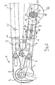
- FIG. 1 shows a mat cutter 1 according to the invention for steel mesh with a protractor and a corner knife 3, which are pivotally mounted to one another in an axis 4.
- the protractor 2 and the corner knife 3 are two Pipe heads 5 and 6, which are opposed to one another about an axis 7 are pivoted, actuated in a conventional manner.
- the Pipe heads 5 and 6 bear on their axis 7 opposite side each a section 8, of which in the drawing only section 8 of the pipe head 6th is shown.
- Section 8 is a tubular handle 9 attached. Section 8, too
- the pipe head stub is in detail A in a cross section along the line a-a.
- the Section 8 has a transverse to the longitudinal axis of the handle pieces 9 seen cruciform cross-section, the section 8 on the inside of the cross-sectionally oval handle 9 in Area of the large semi-axis and in the area of the small Semi-axis rests and the handle 9 in these areas to be led.
- Section 8 points between the wall of the handle 9 leading sections recesses or Grooves 10, which in the longitudinal direction over the entire length of the Section 8 run.
- Figure 2 shows the mat cutter described so far in a view in the direction of movement.
- the same components are provided with the same reference numbers.
- section 8 is on pipe head 6 and accordingly to the pipe head 5 first in one Countersink bevel 11, which in a circumferential Undercut groove 12 passes over.
- the die slope 11 and the Undercut groove 12 allow a clean toast Handle 9 on the pipe head 5 or 6, if this for Reach an interference fit on section 8 becomes.
- Section 8 also carries a groove 14 semicircular cross section, which in a guide surface 15th introduced centrally in the longitudinal direction of the pipe head stump 8 is.
- the groove 14 is set in cross section so that it the protrusion of a weld 15 of the seam welded Handle can accommodate.
- the groove 14 allows Using a welded tube with a Orientation where the seam is in the area of the least Diameter of the oval handle 9 is arranged.
- the neutral fiber of the handle 9 so the least stressed area in which the weld 15 is to be attached uncritically.
- the groove 14 is opposite also in the area of neutral fibers, i.e. in the area of short semiaxis of oval cross-section, another groove 18 introduced in the longitudinal direction of the associated Guide surface is limited by groove walls 19 and 20.
- the Handle 9 is in the area of the groove 18, for example Pressing a ball so plastically deformed that a Area 21 engages in the groove 18 and on both groove flanks 19 and 20 is tight.
- the handles 9 are thereby on the respective section 8 against withdrawal in Secured reliably in the longitudinal direction.
- the protractor 2, the corner knife 3 and the pipe heads 5 and 6 are in practice made of forged tool steel like it is common in such cutting tools.
- a tube from a Light metal alloy can be used.
- Alloy tubes, which are also in the field of neutral Fiber can be seam welded together with the in the tube head stumps 8 introduced grooves 10 into one considerable weight reduction and thus a significant Saving energy in use on a construction site. It has proven to be advantageous if the guide length, ie the Length of the inner parts of the grips 9 cross-shaped bars, about twice as large as the inside diameter of the pipe in the area of the large one Semi-axis.
- the cross-shaped design of the sections 8 also has the Advantage that the tubes of the handles 9 when pressed on sections 8 have a certain freedom in the sense that if the fit is too tight in the area of the grooves 10 can adjust inside.
Landscapes
- Engineering & Computer Science (AREA)
- Mechanical Engineering (AREA)
- Knives (AREA)
- Mutual Connection Of Rods And Tubes (AREA)
- Auxiliary Devices For Machine Tools (AREA)
Description
- Figur 1:
- Einen erfindungsgemäßen Mattenschneider in einer Draufsicht quer zur Bewegungsrichtung; sowie
- Figur 2
- den Mattenschneider gemäß Figur 1 in einer Ansicht in Bewegungsrichtung.
Claims (6)
- Zange mit rohrförmigen Griffstücken (9), die im Betrieb aufeinander zu und voneinander weg zu bewegen sind, und mit Rohrköpfen (5,6), auf die die Griffstücke (9) in Längsrichtung aufgesetzt sind, wobei die Rohrköpfe (5,6) jeweils einen in die Griffstücke einsetzbaren Abschnitt (8) angepaßten Querschnitts aufweisen,
wobei der Abschnitt (8) zwischen der in Bewegungsrichtung liegenden Achse und der quer zur Bewegungsrichtung liegenden Achse in Längsrichtung verlaufende Ausnehmungen (10) aufweist und die Rohrköpfe (5,6) in dem in die Griffstücke (9) einsetzbaren Abschnitt (8) im Querschnitt etwa kreuzförmig gestaltet sind, so
daß in der etwa mit der Bewegungsrichtung zusammenfallenden Achse und der etwa quer zur Bewegungsrichtung liegenden Achse Stege oder Rippen gebildet sind, und die Rohrköpfe (5,6) in dem in die Griffstücke (9) einsetzbaren Abschnitt (8) wenigstens eine in Längsrichtung durch Nutwände (19,20) begrenzte Ausnehmung oder Nut (18) aufweisen,
wobei mit den Nutwänden (19,20) eine formschlüssig gesicherte Verbindung zwischen den Rohrköpfen (5,6) und den Griffstücken (9) hergestellt wird. - Zange nach Anspruch 1, dadurch gekennzeichnet, daß die Griffstücke (9) in ihrer etwa mit der Bewegungsrichtung zusammenfallenden Achse eine größere Dicke aufweisen als in der etwa quer zur Bewegungsrichtung liegenden Achse.
- Zange nach einem der vorhergehenden Ansprüche, dadurch gekennzeichnet, daß die Griffstücke (9) im Querschnitt zumindest abschnittsweise nicht kreisrund ausgebildet sind.
- Zange nach einem der vorhergehenden Ansprüche, dadurch gekennzeichnet, daß die Griffstücke (9) im Querschnitt zumindest abschnittsweise oval sind.
- Zange nach einem der vorhergehenden Ansprüche, dadurch gekennzeichnet, daß die Griffstücke (9) aus nahtgeschweißten Rohren gefertigt sind
- Zange nach Anspruch 5, dadurch gekennzeichnet, daß die geschweißte Naht (15) der Rohre in der etwa quer zur Bewegungsrichtung liegenden Achse, insbesondere im Bereich des kleinsten Durchmessers der Rohre angeordnet ist.
Applications Claiming Priority (2)
| Application Number | Priority Date | Filing Date | Title |
|---|---|---|---|
| DE19644208A DE19644208A1 (de) | 1996-10-24 | 1996-10-24 | Schneidwerkzeug |
| DE19644208 | 1996-10-24 |
Publications (2)
| Publication Number | Publication Date |
|---|---|
| EP0838295A1 EP0838295A1 (de) | 1998-04-29 |
| EP0838295B1 true EP0838295B1 (de) | 2003-04-23 |
Family
ID=7809867
Family Applications (1)
| Application Number | Title | Priority Date | Filing Date |
|---|---|---|---|
| EP97111703A Expired - Lifetime EP0838295B1 (de) | 1996-10-24 | 1997-07-10 | Schneidwerkzeug |
Country Status (3)
| Country | Link |
|---|---|
| EP (1) | EP0838295B1 (de) |
| AT (1) | ATE238121T1 (de) |
| DE (2) | DE19644208A1 (de) |
Families Citing this family (1)
| Publication number | Priority date | Publication date | Assignee | Title |
|---|---|---|---|---|
| WO2000034014A1 (en) * | 1998-12-04 | 2000-06-15 | Colin Robert Lane | Shaft for a tool |
Family Cites Families (6)
| Publication number | Priority date | Publication date | Assignee | Title |
|---|---|---|---|---|
| US2685130A (en) * | 1952-02-12 | 1954-08-03 | Porter Inc H K | Adjustable multiple lever tool |
| DE3221072A1 (de) * | 1982-06-04 | 1983-12-08 | Vereinigte Beckersche Werkzeugfabriken, 5630 Remscheid | Hebeluebersetzte zange |
| US4792256A (en) * | 1986-12-10 | 1988-12-20 | Libman Broom Company | Implement with connector joining handle to working head |
| DE8803016U1 (de) * | 1988-03-05 | 1989-07-06 | Knipex-Werk C. Gustav Putsch, 5600 Wuppertal | Mittenschneider |
| US5168629A (en) * | 1990-08-28 | 1992-12-08 | Frank Willard | Scissor assembly |
| DE9203591U1 (de) * | 1992-03-17 | 1992-05-07 | Chang, Jong-Shing, Shiow Shoei Shi, Chang Huah | Mehrhebeliges Handwerkzeug |
-
1996
- 1996-10-24 DE DE19644208A patent/DE19644208A1/de not_active Withdrawn
-
1997
- 1997-07-10 DE DE59709899T patent/DE59709899D1/de not_active Expired - Lifetime
- 1997-07-10 EP EP97111703A patent/EP0838295B1/de not_active Expired - Lifetime
- 1997-07-10 AT AT97111703T patent/ATE238121T1/de not_active IP Right Cessation
Also Published As
| Publication number | Publication date |
|---|---|
| DE19644208A1 (de) | 1998-04-30 |
| EP0838295A1 (de) | 1998-04-29 |
| ATE238121T1 (de) | 2003-05-15 |
| DE59709899D1 (de) | 2003-05-28 |
Similar Documents
| Publication | Publication Date | Title |
|---|---|---|
| DE1960758C3 (de) | Lichtbogenschweißpistole mit Düsen-Klemmbefestigung | |
| EP0116305A1 (de) | Wasserpumpenzange | |
| EP0462257A1 (de) | Spannfutter für mehrkantige schaftenden von werkzeugen. | |
| DE29916588U1 (de) | Handwerkzeug mit Zangenfunktion | |
| DE102020127061A1 (de) | Umschaltelement für Ratschenschlüssel | |
| DE1625417B2 (de) | Selbstbohrende und gewindeformende Schraube | |
| EP0645217A2 (de) | Schonhammer | |
| DE19505079A1 (de) | In zwei Drehrichtungen betreibbarer Senker | |
| DE69201561T2 (de) | Schere. | |
| EP2076361B1 (de) | Zange | |
| DE9108009U1 (de) | Messer mit am Kropf stumpf angeschweißtem Erl | |
| DE3638404A1 (de) | Saegeblatteinheit | |
| EP0838295A1 (de) | Schneidwerkzeug | |
| DE2251770C2 (de) | Meißelrollenhalterung für Gesteinsbohrköpfe | |
| DE2903833C2 (de) | Klapphackspaten | |
| EP0928237B1 (de) | Bolzenschneider | |
| DE19737129C2 (de) | Zange | |
| DE20113238U1 (de) | Handwerkzeug mit einem elektrohydraulischen Antriebsteil und einem Arbeitskopf | |
| DE2343507B2 (de) | Scharniergelenk für Fenster, Türen o.dgl | |
| DE2218614A1 (de) | Handkurbel | |
| DE102021125710B3 (de) | Kapp- und Zugsäge | |
| DE1914436A1 (de) | Vorrichtung zum zentrischen Spannen von kreisfoermigen Querschnitt aufweisenden Teilen,beispielsweise Rohren | |
| DE4244208A1 (de) | Vorrichtung zum biegefesten Verbinden zweier Rohre | |
| DE2445226C2 (de) | Sägekette für Motorkettensägen | |
| DE488405C (de) | Kombiniertes Werkzeug |
Legal Events
| Date | Code | Title | Description |
|---|---|---|---|
| PUAI | Public reference made under article 153(3) epc to a published international application that has entered the european phase |
Free format text: ORIGINAL CODE: 0009012 |
|
| AK | Designated contracting states |
Kind code of ref document: A1 Designated state(s): AT BE CH DE DK GB IT LI NL |
|
| AX | Request for extension of the european patent |
Free format text: AL;LT;LV;RO;SI |
|
| 17P | Request for examination filed |
Effective date: 19981002 |
|
| AKX | Designation fees paid |
Free format text: AT BE CH DE DK GB IT LI NL |
|
| RBV | Designated contracting states (corrected) |
Designated state(s): AT BE CH DE DK GB IT LI NL |
|
| RIN1 | Information on inventor provided before grant (corrected) |
Inventor name: SUHR, FRANK Inventor name: SCHWANDRAU, SIEGHARDT Inventor name: SCHMIDT, JENS-UWE Inventor name: KRUGMANN, JOACHIM Inventor name: EMHARDT, FRANK Inventor name: ERDMEIER, HANS-UDO |
|
| 17Q | First examination report despatched |
Effective date: 20010130 |
|
| GRAH | Despatch of communication of intention to grant a patent |
Free format text: ORIGINAL CODE: EPIDOS IGRA |
|
| GRAH | Despatch of communication of intention to grant a patent |
Free format text: ORIGINAL CODE: EPIDOS IGRA |
|
| GRAA | (expected) grant |
Free format text: ORIGINAL CODE: 0009210 |
|
| AK | Designated contracting states |
Designated state(s): AT BE CH DE DK GB IT LI NL |
|
| PG25 | Lapsed in a contracting state [announced via postgrant information from national office to epo] |
Ref country code: GB Free format text: LAPSE BECAUSE OF FAILURE TO SUBMIT A TRANSLATION OF THE DESCRIPTION OR TO PAY THE FEE WITHIN THE PRESCRIBED TIME-LIMIT Effective date: 20030423 |
|
| REG | Reference to a national code |
Ref country code: GB Ref legal event code: FG4D Free format text: NOT ENGLISH |
|
| REG | Reference to a national code |
Ref country code: CH Ref legal event code: EP |
|
| REF | Corresponds to: |
Ref document number: 59709899 Country of ref document: DE Date of ref document: 20030528 Kind code of ref document: P |
|
| PGFP | Annual fee paid to national office [announced via postgrant information from national office to epo] |
Ref country code: NL Payment date: 20030721 Year of fee payment: 7 |
|
| PG25 | Lapsed in a contracting state [announced via postgrant information from national office to epo] |
Ref country code: DK Free format text: LAPSE BECAUSE OF FAILURE TO SUBMIT A TRANSLATION OF THE DESCRIPTION OR TO PAY THE FEE WITHIN THE PRESCRIBED TIME-LIMIT Effective date: 20030723 |
|
| PGFP | Annual fee paid to national office [announced via postgrant information from national office to epo] |
Ref country code: AT Payment date: 20030725 Year of fee payment: 7 |
|
| PGFP | Annual fee paid to national office [announced via postgrant information from national office to epo] |
Ref country code: CH Payment date: 20030728 Year of fee payment: 7 |
|
| PG25 | Lapsed in a contracting state [announced via postgrant information from national office to epo] |
Ref country code: BE Free format text: LAPSE BECAUSE OF NON-PAYMENT OF DUE FEES Effective date: 20030731 |
|
| GBV | Gb: ep patent (uk) treated as always having been void in accordance with gb section 77(7)/1977 [no translation filed] |
Effective date: 20030423 |
|
| BERE | Be: lapsed |
Owner name: VEREINIGTE BECKERSCHE WERKZEUGFABRIKEN G.M.B.H. & Effective date: 20030731 |
|
| PLBE | No opposition filed within time limit |
Free format text: ORIGINAL CODE: 0009261 |
|
| STAA | Information on the status of an ep patent application or granted ep patent |
Free format text: STATUS: NO OPPOSITION FILED WITHIN TIME LIMIT |
|
| 26N | No opposition filed |
Effective date: 20040126 |
|
| PG25 | Lapsed in a contracting state [announced via postgrant information from national office to epo] |
Ref country code: AT Free format text: LAPSE BECAUSE OF NON-PAYMENT OF DUE FEES Effective date: 20040710 |
|
| PG25 | Lapsed in a contracting state [announced via postgrant information from national office to epo] |
Ref country code: LI Free format text: LAPSE BECAUSE OF NON-PAYMENT OF DUE FEES Effective date: 20040731 Ref country code: CH Free format text: LAPSE BECAUSE OF NON-PAYMENT OF DUE FEES Effective date: 20040731 |
|
| PG25 | Lapsed in a contracting state [announced via postgrant information from national office to epo] |
Ref country code: NL Free format text: LAPSE BECAUSE OF NON-PAYMENT OF DUE FEES Effective date: 20050201 |
|
| REG | Reference to a national code |
Ref country code: CH Ref legal event code: PL |
|
| NLV4 | Nl: lapsed or anulled due to non-payment of the annual fee |
Effective date: 20050201 |
|
| PG25 | Lapsed in a contracting state [announced via postgrant information from national office to epo] |
Ref country code: IT Free format text: LAPSE BECAUSE OF NON-PAYMENT OF DUE FEES Effective date: 20050710 |
|
| REG | Reference to a national code |
Ref country code: DE Ref legal event code: R082 Ref document number: 59709899 Country of ref document: DE Representative=s name: LENZING GERBER STUTE PARTNERSCHAFTSGESELLSCHAF, DE |
|
| REG | Reference to a national code |
Ref country code: DE Ref legal event code: R082 Ref document number: 59709899 Country of ref document: DE Representative=s name: RGTH RICHTER GERBAULET THIELEMANN HOFMANN PATE, DE Effective date: 20130429 Ref country code: DE Ref legal event code: R082 Ref document number: 59709899 Country of ref document: DE Representative=s name: LENZING GERBER STUTE PARTNERSCHAFTSGESELLSCHAF, DE Effective date: 20130429 Ref country code: DE Ref legal event code: R081 Ref document number: 59709899 Country of ref document: DE Owner name: VBW WERKZEUGFABRIK GMBH, DE Free format text: FORMER OWNER: VBW VEREINIGTE BECKERSCHE WERKZEUGFABRIKEN GMBH & CO. KG, 42857 REMSCHEID, DE Effective date: 20130429 |
|
| REG | Reference to a national code |
Ref country code: DE Ref legal event code: R082 Ref document number: 59709899 Country of ref document: DE Representative=s name: RGTH RICHTER GERBAULET THIELEMANN HOFMANN PATE, DE |
|
| PGFP | Annual fee paid to national office [announced via postgrant information from national office to epo] |
Ref country code: DE Payment date: 20160530 Year of fee payment: 20 |
|
| REG | Reference to a national code |
Ref country code: DE Ref legal event code: R071 Ref document number: 59709899 Country of ref document: DE |