EP0837780B1 - Von hand bewegbarer transportwagen - Google Patents
Von hand bewegbarer transportwagen Download PDFInfo
- Publication number
- EP0837780B1 EP0837780B1 EP97925851A EP97925851A EP0837780B1 EP 0837780 B1 EP0837780 B1 EP 0837780B1 EP 97925851 A EP97925851 A EP 97925851A EP 97925851 A EP97925851 A EP 97925851A EP 0837780 B1 EP0837780 B1 EP 0837780B1
- Authority
- EP
- European Patent Office
- Prior art keywords
- axle
- trolley
- bearing
- section
- retaining means
- Prior art date
- Legal status (The legal status is an assumption and is not a legal conclusion. Google has not performed a legal analysis and makes no representation as to the accuracy of the status listed.)
- Expired - Lifetime
Links
Images


Classifications
-
- B—PERFORMING OPERATIONS; TRANSPORTING
- B60—VEHICLES IN GENERAL
- B60B—VEHICLE WHEELS; CASTORS; AXLES FOR WHEELS OR CASTORS; INCREASING WHEEL ADHESION
- B60B33/00—Castors in general ; Anti-clogging castors
- B60B33/0002—Castors in general ; Anti-clogging castors assembling to the object, e.g. furniture
Definitions
- the invention relates to a manually movable trolley, the Chassis is equipped with axle pieces and each axle piece with the help a fastening section is welded to the chassis, each Axle piece a downward, located on a vertical axis Axis section and one on each axle section Swivel castor attached and against by a flexible elastic locking device Loosening is secured.
- European patent application EP 0 242 756 A3 describes such a trolley designed as a shopping trolley.
- Whose chassis has two different axle pieces, which carry the castors.
- the axle pieces on the rear of the chassis are part of a quadruple-curved wire frame.
- the two wire frames are designed to carry the basket of the shopping cart.
- the wire frames are welded to the long sides of the chassis via vertical fastening sections, the rear sections being extended downwards beyond the long sides and each forming a downward axis section for attaching a steering castor.
- two further axle pieces are provided, which are also welded to the chassis by means of a fastening section and each carry a steering roller with their axle sections facing downwards.
- the swivel castors are placed on the axle sections from below and secured against loosening by a locking device in the form of an axial retaining ring.
- the drawing shows that the diameter of the axle sections corresponds to the diameter of the fastening sections. Furthermore, the distance between the welds is equal to the distance between the two longitudinal wires that form the long sides of the chassis.
- the proposed solution may be strikingly simple, but if you know that the wire thickness of chassis made of wire is set to a maximum of 14 mm and the wires do not have excessive bending strength due to their ability to bend quickly the disadvantages of the proposed solution.
- the castors of the transport vehicle just described have two fork legs, which are connected via a wall bridge and carry the axle for the wheel. The fork legs are attached to a separate fork head, which is formed from two complementary head pieces.
- the fork head engages around an axle pin together with a bearing element that forms when the head pieces are assembled.
- a particular disadvantage of this swivel castor is that a bolt has to be passed through the fork leg and through the split bearing element for mounting on the axle journal and then the ends of the bolt have to be compressed. This type of assembly is cumbersome, time consuming and therefore expensive.
- the Swivel bearing designed as a deep groove ball bearing or as a roller bearing are that each swivel castor is a minimal piece along the vertical axis is arranged up and down movable and that the securing means for automatic locking with the axle pieces are determined.
- axle pieces it is possible to choose the diameter of the axle sections at least 14 mm, since the axle pieces are no longer made of wire.
- a material can also be selected for the axle pieces that, in addition to having good welding properties, also has a higher bending strength than axle pieces made from wire.
- the axle pieces can therefore absorb greater impact forces without being bent.
- a further advantage is that instead of plain bearings made of plastic, as proposed in EP 0 242 756 A3, grooved ball bearings or roller bearings made of steel are now provided, which are able to absorb higher forces than bearings made of elastic plastic. Knocking out of bearings made of steel is much less to be feared than is possible with plain bearings made of plastic.
- the proposed solution also advantageously allows assembly of the swivel castors as finished structural units in a very short time, because it suffices to attach the swivel castors to the axle pin and then a short, directed in the longitudinal direction of the swivel pin on a swivel castor in order to close them on the swivel pin fasten and lock.
- the at least one securing means which is arranged in a stationary manner on the wheel fork, automatically snaps into an annular groove located on the axle journal, so that the castor wheel is secured. Any other mounting options required with the securing means, such as those known from the prior art, are no longer required.
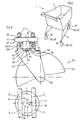
- the hand-movable trolley 1 shown in FIG. 1 has one Chassis 3, which carries a device 2 for the transport of goods.
- the trolley 1 can be designed in many different ways. Its shape is For the invention is essentially insignificant, but the chassis 3 Axle pieces 10, which are welded to the chassis 3 and on each a swivel castor 20 is attached and secured against loosening by means 40 is secured.
- the chassis 3 is either indicated by the representation of wires 7 or by a tube 8, the wires 7 or the tubes 8 are designed in a straight line and or curved could be.
- Fig. 2 shows two wires 7 of the chassis 3 and an axle piece 10 with mounted steering roller 20.
- the axle piece 10 has a fastening section 11, which has a horizontally arranged annular elevation 12 has, on which the two wires 7 placed by spot welding and are connected.
- the fastening section 11 is designed as a disc, wherein the two wires 7 intersect the annular elevation 12 so that four welding points 9 are formed, which enclose a plane.
- the so created Four-point support results in an extremely stable welded connection.
- punctiform elevations can also be used 12 may be provided on the underside 13 of the fastening section 11, an axle section 15 is formed with a cylindrical cross section.
- the Axis section 15 is directed downwards.
- the cross section 14 or the cross-sectional area of the floor plan of the fastening section 11 is larger than the cross section 16 or Cross-sectional area of the plan of the axle section 15.
- a steel ball bearing 31 is placed and by a located in a circumferential groove 19 on the axle section 15 Securing means 40, for example supported by a resilient axial retaining ring and secured against loosening.
- the deep groove ball bearing 31 is thus supported on the axle section 15 and on a securing means 40.
- the deep groove ball bearing 31 is fixed in a known manner in a bearing housing 25 one Wheel fork 21 used, which is rotatable about a horizontal axis 23 Wheel 24 carries.
- the swivel castor 20 designed in this way can be used as a deep groove ball bearing 31 swivel designed pivot bearing 30 about a vertical axis 26, which is identical to the longitudinal axis of the axle piece 15.
- Die Inner chamfer 34 of the inner ring 32 of the deep groove ball bearing 31 is at the top, the Attachment section 11 adjacent end strongly rounded or beveled, while the inner chamfer 34 of the inner ring 32 at the lower end, the strikes the securing means 40, is formed with sharp edges, so that the inner ring 32 on the annular slit made of spring steel Belay means 40 is better supported.
- the castor 20 is from below forth on the axle section 15.
- the heavily rounded shape makes it easier Inner chamfer 34 is placed on the axle section 15 and presses the securing means 40 in the horizontal located on the axle section 15 arranged groove 19 so that the upper end 27 of the bearing housing 25th abuts the underside 13 of the fastening section 11 when plugged in, while at the same time the securing means 40 is relaxed slightly enlarged radially outwards and a support for the inner ring 32 of the Deep groove ball bearing 31 forms.
- the distance between the bottom 13 of the Fastening section 11 and the securing means 40 is chosen so that the clamped castor 20 along the vertical axis 26 a minimal Pieces can be moved up and down.
- the swivel castor 20 corresponds to their design is roughly the same as that described in DE 25 43 211.5 is.
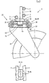
- Fig. 3 shows a steering roller 20 equipped with a roller bearing 35, the is attached to an axle piece 10.
- the chassis 3 is through three wires 7 shown.
- the fastening section 11 of the axle piece 10 is reminiscent of an inverted "T", with the upward section 18 two wires 7 and a wire 7 welded to the horizontal section 18 ' are.
- the example is intended to illustrate that there are a large number of There are ways to design the mounting portion 11 so that a extremely stable connection between the axle piece 10 and the chassis 3 of the trolley 1 is possible.
- the cross section 14 of the floor plan the fastening section 11, cf. Top view is larger than the cross section 16 of the plan of the axle section 15 on which the steering roller 20th attached and secured against loosening by a securing means 40.
- the swivel castor 20 roughly corresponds to the insertion bracket excluded those swivel castors as used in German utility model G 92 16 608.3 are described.
- the steel roller bearing 35 which as Swivel bearing 30 acts, is in a known manner by bearing disks 36, 37, 38 formed with the help of steel balls 39 and 21 with the wheel fork are assembled into one unit.
- the upper bearing plate 36 is on the upper inside slightly chamfered so that the castor 20 from below can be attached to the axle section 15 in the same way as described in advance.
- the securing means 40 deviates in such a way that the swivel castor 20 can be attached so far that it is on the underside 13 of the mounting section 11 strikes while the securing means 40 relaxes and blocks the castor 20 in the way provides so that the castor 20 can no longer detach from the axle piece 10 can.
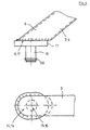
- Fig. 4 shows a further possibility, such as an axle piece 10 with a Chassis 3 can be connected.
- the chassis 3 has in a known Show two longitudinal bars 4, one of which is shown in sections.
- the lower end of the longitudinal spar 4 consisting of a semicircular tube 5 is formed by a flat horizontal cutting surface 6.
- the fastening section 11 of the axle piece 10 also closes at the top with a plane horizontally arranged surface 17, so that the longitudinal beam 4 with its Cut surface 6 placed flat and with the disc-shaped fastening section 11 can be welded.
- the steering roller 20 shown in FIG. 5 is oriented in its construction to the steering roller described in FIG. 2.
- at least one securing means 40 is provided on the underside of the pivot bearing 30, and adjacent to its outer ring 33, the teeth 41 of which strive radially from the outside inwards and in the center, on the vertical axis 26 of the steering roller 20 located to form a predetermined opening 42.
- the at least one securing means 40 is clamped between the pivot bearing 30 and at least one further support means 43, which is provided on the wheel fork 21 and is intended for fastening the pivot bearing 30, and is thereby held stationary.
- the at least one support means 43 is either formed by an annular bead which is worked out or rolled out of the inner wall of the bearing housing 25 during the assembly process of the pivot bearing 30 and the support means 43, or notch-like projections are provided as support means 43, which point-like in a known manner from the Inner wall of the bearing housing 25 are pressed out. In this way, the pivot bearing 30 and the at least one securing means 40 are fixed in place in the bearing housing 25. Since the pivot bearing 30 is braced only via its outer ring 33, the inner ring 32 can rotate.
- an axle piece 10 which is arranged in a fixed position on a transport carriage 1, is shown in the drawing, onto which the swivel castor 20 can be plugged in the direction of the arrow.
- the axle piece 10 penetrates the inner ring 32 of the pivot bearing 30 with a precise fit.
- the teeth 41 of the securing means 40 engage in the groove 19 of the axle piece 10 so that the steering roller 20, with its upper limit 29, on the fastening section located on the axle piece 10 11 is supported on the axle piece 10 by means of the at least one securing means 40 between the securing means 40 and the fastening section 11 and secured against axial displacement.
- a steering roller 20 is fastened to the axle journal 10, which has already been described in more detail in FIG. 3.
- a securing means 40 in the form of a disc equipped with teeth 41 and made of spring steel is laid flat on the lower running disk 38 and fixed in place with the same or similar supporting means 43.
- the at least one securing means 40 is clamped and held between the swivel bearing 30 and at least one additional support 43, which is provided on the wheel fork 21 and is intended for fastening the swivel bearing 30.
- the radially inwardly directed teeth 41 of the securing means 40 forming the predetermined opening 42 are also supported in this embodiment on the annular groove 19 of the axle piece 10.
- the pivot bearing 30 rests with its upper running disk 36 on the fastening section 11 of the axle piece 10 located on a transport carriage 1.
- the middle bearing plate 37 is formed in a known manner by the back, which connects the two fork legs 22.
- more than one securing means 40 can also be provided.
- at least one support means 43 which is worked out of the wheel fork 21
- known support means 43 to be attached separately such as retaining rings, spring washers or the like, can also be provided, which snap into predetermined recesses.
Landscapes
- Engineering & Computer Science (AREA)
- Mechanical Engineering (AREA)
- Handcart (AREA)
- Steering-Linkage Mechanisms And Four-Wheel Steering (AREA)
- Rollers For Roller Conveyors For Transfer (AREA)
Applications Claiming Priority (5)
| Application Number | Priority Date | Filing Date | Title |
|---|---|---|---|
| DE19619579 | 1996-05-15 | ||
| DE1996119579 DE19619579A1 (de) | 1996-05-15 | 1996-05-15 | Lenkrolle zum Aufstecken auf einen Achszapfen |
| DE19643121 | 1996-10-18 | ||
| DE1996143121 DE19643121A1 (de) | 1996-10-18 | 1996-10-18 | Von Hand bewegbarer Transportwagen |
| PCT/DE1997/001013 WO1997043135A1 (de) | 1996-05-15 | 1997-05-15 | Von hand bewegbarer transportwagen |
Publications (2)
| Publication Number | Publication Date |
|---|---|
| EP0837780A1 EP0837780A1 (de) | 1998-04-29 |
| EP0837780B1 true EP0837780B1 (de) | 2001-11-07 |
Family
ID=26025730
Family Applications (1)
| Application Number | Title | Priority Date | Filing Date |
|---|---|---|---|
| EP97925851A Expired - Lifetime EP0837780B1 (de) | 1996-05-15 | 1997-05-15 | Von hand bewegbarer transportwagen |
Country Status (6)
| Country | Link |
|---|---|
| EP (1) | EP0837780B1 (cs) |
| CZ (1) | CZ10398A3 (cs) |
| DE (1) | DE59705263D1 (cs) |
| HU (1) | HUP9900708A2 (cs) |
| PL (1) | PL324457A1 (cs) |
| WO (1) | WO1997043135A1 (cs) |
Families Citing this family (2)
| Publication number | Priority date | Publication date | Assignee | Title |
|---|---|---|---|---|
| EP0918010B1 (de) * | 1997-11-22 | 2004-05-26 | Wanzl Metallwarenfabrik Gmbh | Einkaufswagen |
| FR2934023B1 (fr) * | 2008-07-18 | 2010-09-10 | Caddie | Dispositif de fixation d'un roulement a un axe |
Family Cites Families (10)
| Publication number | Priority date | Publication date | Assignee | Title |
|---|---|---|---|---|
| FR2191630A5 (cs) * | 1972-06-29 | 1974-02-01 | Reunis Sa Ateliers | |
| DE2543211C2 (de) * | 1975-09-27 | 1978-10-26 | Wanzl Metallwarenfabrik Kg, 8874 Leipheim | Lenkrolle für von Hand bewegte Fahrzeuge insbesondere für Einkaufswagen |
| DE2548646A1 (de) * | 1975-10-24 | 1977-05-05 | Maruwa Echo Co | Abnehmbares roll-fahrwerk |
| FR2529139A1 (fr) * | 1982-06-29 | 1983-12-30 | Reunis Sa Ateliers | Dispositif de montage d'une roue sur le chassis d'un chariot de transport, de manutention ou destine aux magasins a libre service |
| DE3410536A1 (de) * | 1984-03-22 | 1985-10-03 | Albert Schulte Söhne GmbH & Co, 5632 Wermelskirchen | Laufrolle |
| EP0190376B1 (de) * | 1985-02-04 | 1988-05-11 | TENTE-ROLLEN GmbH & Co. | Halterung von Rollen, insbesondere Lenkrollen, am Fahrgestell eines Wagens |
| DE8511713U1 (de) * | 1985-04-19 | 1985-08-08 | Albert Schulte Söhne GmbH & Co, 5632 Wermelskirchen | Laufrolle |
| FR2581933B3 (fr) * | 1985-05-15 | 1987-07-10 | Reunis Sa Ateliers | Chariot de transport, notamment pour la clientele de magasins a libre-service. |
| DE3613136C2 (de) * | 1986-04-18 | 1993-09-30 | Schulte Soehne Gmbh Co A | Laufrolle für Transportwagen |
| DE9216608U1 (de) * | 1992-02-26 | 1993-06-24 | Tente-Rollen Gmbh & Co, 5632 Wermelskirchen | Einsteckhalterung, insbesondere an Rollen, z.B. Lenkrollen |
-
1997
- 1997-05-15 CZ CZ98103A patent/CZ10398A3/cs unknown
- 1997-05-15 DE DE59705263T patent/DE59705263D1/de not_active Expired - Lifetime
- 1997-05-15 PL PL97324457A patent/PL324457A1/xx unknown
- 1997-05-15 WO PCT/DE1997/001013 patent/WO1997043135A1/de not_active Ceased
- 1997-05-15 EP EP97925851A patent/EP0837780B1/de not_active Expired - Lifetime
- 1997-05-15 HU HU9900708A patent/HUP9900708A2/hu unknown
Also Published As
| Publication number | Publication date |
|---|---|
| PL324457A1 (en) | 1998-05-25 |
| DE59705263D1 (de) | 2001-12-13 |
| WO1997043135A1 (de) | 1997-11-20 |
| EP0837780A1 (de) | 1998-04-29 |
| CZ10398A3 (cs) | 1998-07-15 |
| HUP9900708A2 (hu) | 1999-06-28 |
Similar Documents
| Publication | Publication Date | Title |
|---|---|---|
| DE2926596A1 (de) | Transportkarre | |
| DE2839344A1 (de) | Fusschutz fuer ein rad oder eine rolle an einem flurfahrzeug | |
| EP0837780B1 (de) | Von hand bewegbarer transportwagen | |
| DE19643121A1 (de) | Von Hand bewegbarer Transportwagen | |
| DE3631998C2 (cs) | ||
| EP0562264B1 (de) | Von Hand bewegbarer Transportwagen | |
| DE3521836C2 (de) | Vorrichtung zum Verstellen eines Fahrzeugsitzes | |
| EP0432515B1 (de) | Einkaufswagen | |
| EP0927676B1 (de) | Stapelbarer Transportwagen | |
| DE8123716U1 (de) | Unterhalb des warenkorbes am fahrgestell eines einkaufswagens fuer selbstbedienungsmaerkte anzubringendes gestaenge | |
| DE3613136C2 (de) | Laufrolle für Transportwagen | |
| DE3444256C2 (de) | Stapelbarer Einkaufswagen | |
| DE4232464A1 (de) | Fahrbares Rollengestell für Fahrräder und Mofas | |
| DE818773C (de) | Rollstuetze | |
| EP0918010B1 (de) | Einkaufswagen | |
| EP1318028B1 (de) | Rollenvorrichtung für einen Transportwagen | |
| DE3228907C2 (de) | Zusammenlegbarer Zustellwagen | |
| DE10121382A1 (de) | Bodenbearbeitungsgerät zur Zerkleinerung von grobschollig verarbeiteten Flächen | |
| DE3931091A1 (de) | Einkaufswagen | |
| DE2508231C3 (de) | Fahrwerk für eine auf einer Schiene rollende Laufkatze | |
| EP0296326A2 (de) | Gefederte Schwerlastrolle | |
| DE2643554C2 (de) | Fahrgestell für Regenautomaten | |
| DE8903717U1 (de) | Gefederte Schwerlastrolle | |
| DE1200698B (de) | Schwenkradanordnung bei Flurfoerderfahrzeugen | |
| DE2625245C2 (de) | Vorrichtung zur Verbesserung der Standfestigkeit landwirtschaftlicher Fahrzeuge |
Legal Events
| Date | Code | Title | Description |
|---|---|---|---|
| PUAI | Public reference made under article 153(3) epc to a published international application that has entered the european phase |
Free format text: ORIGINAL CODE: 0009012 |
|
| 17P | Request for examination filed |
Effective date: 19971121 |
|
| AK | Designated contracting states |
Kind code of ref document: A1 Designated state(s): DE ES FR GB IT NL SE |
|
| RAP1 | Party data changed (applicant data changed or rights of an application transferred) |
Owner name: WANZL METALLWARENFABRIK GMBH |
|
| 17Q | First examination report despatched |
Effective date: 19990923 |
|
| GRAG | Despatch of communication of intention to grant |
Free format text: ORIGINAL CODE: EPIDOS AGRA |
|
| GRAG | Despatch of communication of intention to grant |
Free format text: ORIGINAL CODE: EPIDOS AGRA |
|
| GRAG | Despatch of communication of intention to grant |
Free format text: ORIGINAL CODE: EPIDOS AGRA |
|
| GRAH | Despatch of communication of intention to grant a patent |
Free format text: ORIGINAL CODE: EPIDOS IGRA |
|
| GRAH | Despatch of communication of intention to grant a patent |
Free format text: ORIGINAL CODE: EPIDOS IGRA |
|
| GRAA | (expected) grant |
Free format text: ORIGINAL CODE: 0009210 |
|
| AK | Designated contracting states |
Kind code of ref document: B1 Designated state(s): DE ES FR GB IT NL SE |
|
| PG25 | Lapsed in a contracting state [announced via postgrant information from national office to epo] |
Ref country code: NL Free format text: LAPSE BECAUSE OF FAILURE TO SUBMIT A TRANSLATION OF THE DESCRIPTION OR TO PAY THE FEE WITHIN THE PRESCRIBED TIME-LIMIT Effective date: 20011107 Ref country code: IT Free format text: LAPSE BECAUSE OF FAILURE TO SUBMIT A TRANSLATION OF THE DESCRIPTION OR TO PAY THE FEE WITHIN THE PRE;WARNING: LAPSES OF ITALIAN PATENTS WITH EFFECTIVE DATE BEFORE 2007 MAY HAVE OCCURRED AT ANY TIME BEFORE 2007. THE CORRECT EFFECTIVE DATE MAY BE DIFFERENT FROM THE ONE RECORDED.SCRIBED TIME-LIMIT Effective date: 20011107 |
|
| REF | Corresponds to: |
Ref document number: 59705263 Country of ref document: DE Date of ref document: 20011213 |
|
| REG | Reference to a national code |
Ref country code: GB Ref legal event code: IF02 |
|
| PG25 | Lapsed in a contracting state [announced via postgrant information from national office to epo] |
Ref country code: SE Free format text: LAPSE BECAUSE OF FAILURE TO SUBMIT A TRANSLATION OF THE DESCRIPTION OR TO PAY THE FEE WITHIN THE PRESCRIBED TIME-LIMIT Effective date: 20020207 |
|
| ET | Fr: translation filed | ||
| GBT | Gb: translation of ep patent filed (gb section 77(6)(a)/1977) |
Effective date: 20020214 |
|
| NLV1 | Nl: lapsed or annulled due to failure to fulfill the requirements of art. 29p and 29m of the patents act | ||
| PG25 | Lapsed in a contracting state [announced via postgrant information from national office to epo] |
Ref country code: ES Free format text: LAPSE BECAUSE OF FAILURE TO SUBMIT A TRANSLATION OF THE DESCRIPTION OR TO PAY THE FEE WITHIN THE PRESCRIBED TIME-LIMIT Effective date: 20020530 |
|
| PLBE | No opposition filed within time limit |
Free format text: ORIGINAL CODE: 0009261 |
|
| STAA | Information on the status of an ep patent application or granted ep patent |
Free format text: STATUS: NO OPPOSITION FILED WITHIN TIME LIMIT |
|
| 26N | No opposition filed | ||
| PGFP | Annual fee paid to national office [announced via postgrant information from national office to epo] |
Ref country code: GB Payment date: 20040512 Year of fee payment: 8 |
|
| PG25 | Lapsed in a contracting state [announced via postgrant information from national office to epo] |
Ref country code: GB Free format text: LAPSE BECAUSE OF NON-PAYMENT OF DUE FEES Effective date: 20050515 |
|
| GBPC | Gb: european patent ceased through non-payment of renewal fee |
Effective date: 20050515 |
|
| PGFP | Annual fee paid to national office [announced via postgrant information from national office to epo] |
Ref country code: DE Payment date: 20130531 Year of fee payment: 17 |
|
| PGFP | Annual fee paid to national office [announced via postgrant information from national office to epo] |
Ref country code: FR Payment date: 20130604 Year of fee payment: 17 |
|
| REG | Reference to a national code |
Ref country code: DE Ref legal event code: R119 Ref document number: 59705263 Country of ref document: DE |
|
| REG | Reference to a national code |
Ref country code: FR Ref legal event code: ST Effective date: 20150130 |
|
| REG | Reference to a national code |
Ref country code: DE Ref legal event code: R119 Ref document number: 59705263 Country of ref document: DE Effective date: 20141202 |
|
| PG25 | Lapsed in a contracting state [announced via postgrant information from national office to epo] |
Ref country code: DE Free format text: LAPSE BECAUSE OF NON-PAYMENT OF DUE FEES Effective date: 20141202 |
|
| PG25 | Lapsed in a contracting state [announced via postgrant information from national office to epo] |
Ref country code: FR Free format text: LAPSE BECAUSE OF NON-PAYMENT OF DUE FEES Effective date: 20140602 |