EP0835181B1 - Prägewalze für eine Prägevorrichtung - Google Patents
Prägewalze für eine Prägevorrichtung Download PDFInfo
- Publication number
- EP0835181B1 EP0835181B1 EP96909045A EP96909045A EP0835181B1 EP 0835181 B1 EP0835181 B1 EP 0835181B1 EP 96909045 A EP96909045 A EP 96909045A EP 96909045 A EP96909045 A EP 96909045A EP 0835181 B1 EP0835181 B1 EP 0835181B1
- Authority
- EP
- European Patent Office
- Prior art keywords
- embossing
- roller
- die ring
- ring
- embossing roller
- Prior art date
- Legal status (The legal status is an assumption and is not a legal conclusion. Google has not performed a legal analysis and makes no representation as to the accuracy of the status listed.)
- Expired - Lifetime
Links
- 238000004049 embossing Methods 0.000 title claims description 101
- 125000006850 spacer group Chemical group 0.000 claims abstract description 27
- 239000000463 material Substances 0.000 claims abstract description 10
- 238000010438 heat treatment Methods 0.000 claims description 6
- 238000009413 insulation Methods 0.000 abstract description 5
- 230000002093 peripheral effect Effects 0.000 abstract 1
- 239000000758 substrate Substances 0.000 description 17
- 230000008901 benefit Effects 0.000 description 8
- 238000000034 method Methods 0.000 description 5
- 239000011888 foil Substances 0.000 description 3
- 230000008878 coupling Effects 0.000 description 2
- 238000010168 coupling process Methods 0.000 description 2
- 238000005859 coupling reaction Methods 0.000 description 2
- 238000000926 separation method Methods 0.000 description 2
- 238000012549 training Methods 0.000 description 2
- 241001295925 Gegenes Species 0.000 description 1
- 239000012790 adhesive layer Substances 0.000 description 1
- 230000015572 biosynthetic process Effects 0.000 description 1
- 238000009529 body temperature measurement Methods 0.000 description 1
- 238000013461 design Methods 0.000 description 1
- 230000000694 effects Effects 0.000 description 1
- 238000005485 electric heating Methods 0.000 description 1
- 239000012530 fluid Substances 0.000 description 1
- 230000012447 hatching Effects 0.000 description 1
- 230000001771 impaired effect Effects 0.000 description 1
- 239000002184 metal Substances 0.000 description 1
- 238000005096 rolling process Methods 0.000 description 1
- 238000012546 transfer Methods 0.000 description 1
- 238000011144 upstream manufacturing Methods 0.000 description 1
- 230000037303 wrinkles Effects 0.000 description 1
Images


Classifications
-
- B—PERFORMING OPERATIONS; TRANSPORTING
- B41—PRINTING; LINING MACHINES; TYPEWRITERS; STAMPS
- B41F—PRINTING MACHINES OR PRESSES
- B41F19/00—Apparatus or machines for carrying out printing operations combined with other operations
- B41F19/02—Apparatus or machines for carrying out printing operations combined with other operations with embossing
- B41F19/06—Printing and embossing between a negative and a positive forme after inking and wiping the negative forme; Printing from an ink band treated with colour or "gold"
-
- B—PERFORMING OPERATIONS; TRANSPORTING
- B44—DECORATIVE ARTS
- B44B—MACHINES, APPARATUS OR TOOLS FOR ARTISTIC WORK, e.g. FOR SCULPTURING, GUILLOCHING, CARVING, BRANDING, INLAYING
- B44B5/00—Machines or apparatus for embossing decorations or marks, e.g. embossing coins
- B44B5/02—Dies; Accessories
- B44B5/026—Dies
-
- B—PERFORMING OPERATIONS; TRANSPORTING
- B44—DECORATIVE ARTS
- B44B—MACHINES, APPARATUS OR TOOLS FOR ARTISTIC WORK, e.g. FOR SCULPTURING, GUILLOCHING, CARVING, BRANDING, INLAYING
- B44B5/00—Machines or apparatus for embossing decorations or marks, e.g. embossing coins
- B44B5/0004—Machines or apparatus for embossing decorations or marks, e.g. embossing coins characterised by the movement of the embossing tool(s), or the movement of the work, during the embossing operation
- B44B5/0009—Rotating embossing tools
-
- B—PERFORMING OPERATIONS; TRANSPORTING
- B44—DECORATIVE ARTS
- B44B—MACHINES, APPARATUS OR TOOLS FOR ARTISTIC WORK, e.g. FOR SCULPTURING, GUILLOCHING, CARVING, BRANDING, INLAYING
- B44B5/00—Machines or apparatus for embossing decorations or marks, e.g. embossing coins
- B44B5/02—Dies; Accessories
Definitions
- the invention relates to an embossing device intended embossing roller, which has a central carrier roller and Embossing dies spaced apart in the circumferential direction has, at least one on the carrier roller Stamp ring is attached, both of which are axially apart spaced edge sections to the defined system with at least one associated pressure roller Spacer rings are formed, and the at least one Stamp ring between the two associated spacer rings is formed with the dies.
- An embossing roller of the type mentioned above is from CH-A 322 275 and known from US-A 3,217,637. With the from the first known CH-A 322 275 known embossing roller act with this several cylinders different Printing process together. The contact pressure of the different cylinders on the embossing roller, i.e. on the single impression cylinder, be different. At the out of the aforementioned embossing roller known from US Pat. No. 3,217,637 are the Embossing stamps only along a portion of the circumference of the Embossing roller provided.
- An embossing roller is known from WO 94/13487 A1, in which a separate embossing roller is required for different substrates to be embossed in accordance with the division of the benefits.
- This means that such a known embossing roller is only suitable for embossing large embossing runs, because such embossing rollers are expensive and, as it were, have no flexibility.
- the respective decor transfer from the embossing film to the substrate because the pressure rollers that press against the embossing roller only compensate for the above-mentioned deviations from the ideal cylindrical shape of the embossing roller or compensate for tolerances is possible.
- From DE-PS 233 239 is one for an embossing device intended embossing roller known that a central Carrier roller and spaced apart in the circumferential direction Has embossing stamp, with a number on the carrier roller Stamp rings are attached closely adjacent.
- the Stamp rings are between two side spacer rings arranged. These two side spacer rings are used not there for the defined creation of an associated one Pinch roller but for pushing through and setting Attachment rods to the closely spaced To hold stamp rings together.
- DE 27 53 296 C2 describes a bearer ring arrangement to achieve a defined center distance between two Printing unit cylinders of a rotary printing unit with two each on one end of the two printing unit cylinders attached bearer rings, with the printing unit cylinders to run around and under tension and constant mutual contact can roll, and at least one with its central bore attached to the axis of the associated printing unit cylinder is.
- the bearer ring Support surface convex on the axis of the printing unit cylinder and the bearing surface in the central bore of the The bearer is concavely curved.
- U1 is an embossing roller with a heated roller core and a supported on it its circumferential surface engraved roll shell known, wherein the roller core at least in the area of its support the roller shell made of a material with a larger Coefficient of thermal expansion exists as the roll shell.
- the invention has for its object an embossing roller of the type mentioned at the beginning, in which a variable arrangement of the dies as required is possible, and at which tolerances or possible Deviations from the ideal cylinder shape of the embossing roller and their concentricity can be compensated with simple means are.
- This task is the beginning of an embossing roller mentioned type according to the invention solved by the / everyone Stamp ring on the carrier roller dimension and is materially adjusted so that the / everyone Stamp ring at room temperature on the carrier roller is adjustable and with increased embossing or Operating temperature of the embossing roller the thermal expansion the / each stamp ring fixed to the carrier roller that the / each stamp ring between the two lateral ones Spacer rings and between adjacent dies Has heat insulating part, and that to the / each stamp ring Connect covers on the side.
- the dies are expediently in The circumferential direction of the stamp ring is provided equidistant.
- a stamp ring can be attached to the central carrier roller his; but are preferably on the central carrier roller several stamp rings attached. Because of that Embossing stamps are formed on stamp rings, it is possible, a corresponding on the central embossing roller Arrange the number of stamp rings as required. Here is the axial distance between the adjacent stamp rings easily adjustable as required. Through the Selection of a suitable stamp ring is for example also the division of the dies in the circumferential direction of the Embossing roller can be selected as required.
- each Stamp ring and the central carrier roller At normal room temperature is between each Stamp ring and the central carrier roller a sliding or Given sliding seat tolerance, so that the respective Stamp ring in the axial direction of the central carrier roller is adjustable as desired.
- the material selection for the Stamp ring and the central carrier roller is like this met that the central carrier roller at increased operating or embossing temperature of the embossing roller expands more than the / each stamp ring, so that at the embossing or operating temperature of the embossing roller between the central carrier roller and the / each stamp ring Press fit results in what the / each stamp ring on the central carrier roller is fixed.
- the / each stamp ring is expediently provided with a Provide heating device.
- This heater can it is an electric heater.
- This heater is an accurate one Regulation of the temperature on the dies of each Stamp ring and in particular a precise regulation of the Temperature on the front or stamp surfaces of the individual Embossing stamp possible.
- the individual stamp of the / each stamp ring is the appropriate stamp ring with Temperature measurement sensors provided with a Control device are connected, which to the said Use a suitable heating device.
- the / each stamp ring between the two side spacer rings and between the neighboring stamps has a heat insulating part, there is a thermal separation between the Embossing stamps or their front or embossing surfaces.
- This Heat insulating parts expediently have a Outer surface on that of the outer surface of the embossing roller corresponds.
- the pinch rollers continuously and roll evenly on the cylinder jacket is one Embossing roller with spaced apart, individual Stamping the rolling process accordingly discontinuous. That means the pinch rollers can be used the necessary to carry out the embossing process Press in the gaps between neighboring ones Embossing stamps are moved into it.
- the between heat-insulating parts provided adjacent stamps are not suitable for the necessary counterforces to raise; They give slightly due to the material after. Especially in the case of a so-called delay of Embossing roller, which is often not due to the temperature can be reliably excluded, can be serious Problems arise.
- the present invention provides with simple means reliable remedy that on the side next to the spaced stamps the two spacer rings are provided against which the at least one associated pressure roller of the Embossing device presses.
- the two spacer rings are provided against which the at least one associated pressure roller of the Embossing device presses.
- Spacer rings on the embossed substrate clearly Leave impressions, which then the overprintability can restrict.
- you can the two in the embossing roller according to the invention Spacer rings of the / each stamp ring with chamfer surfaces be trained. By training each Pair of spacer rings with such chamfer surfaces there is the advantage that the overprintability is not is restricted.
- the covers can in the embossing roller according to the invention each consist of a metal sheet. They don't serve only a suitable design of the embossing cylinder, but also to the outside of the central carrier roller heat insulate.
- the carrier roller is namely expediently also with a heating device Mistake. This heater can, for example, from commercially available electric heating cartridges.
- the embossing roller according to the invention d. H. from the outer shell of her central carrier roller at least one elongated Strip element protrudes that in the axial direction of Carrier roller oriented and laterally next to the at least a stamp ring with suction openings is formed.
- the suction openings that have suitable Hose lines with a vacuum source fluid are connectable, it is reliably possible to get one to fix the embossing substrate on the embossing roller.
- Minting a so-called endless substrate Feed movement of the substrate in particular by a corresponding clamping between the spacer rings of the / each stamp ring and the associated pressure rollers guaranteed.
- the substrate transport becomes arc-shaped substrates especially of the elongated ledge elements with their Suction openings taken over.
- Suction openings are expediently the leaf or Defined arc start adopted.
- the Sheets or sheets for example, from one of the Embossing station upstream contact roller on the at least pushed a last element.
- at least a strip element has stop ribs on the side are provided in addition to the at least one stamp ring and project radially beyond the at least one stamp ring.
- stop ribs On these stop ribs come the one to be stamped Bow with its leading edge precisely defined to the system and is formed by the elongated last element Suction openings on the last element and thus on the Embossing roller sucked in. After performing the The corresponding embossing process is the negative pressure canceled. Then can through the suction openings Compressed air is blown out, causing the embossed Substrate sheets or sheets from the stop ribs or from the embossing roller repelled and for example by Conveyor belts are taken over.
- the temperature on the front or stamp surfaces the die is very precise and easy to adjust, and dag between the stamping surfaces mentioned and the non-defining spaces between the Stamping through thermal separation
- Heat insulation parts is easy to implement.
- the Heat insulating parts are to be given the cylindrical shape around the Length of the film to be peeled off according to the Keep arc length because without such heat insulation parts follow the polygon shape from stamp to stamp would. This would reduce the length of the film the division of the stamp spacing on the cylinder or Imprints on the paper sheet to be embossed or the like. That would the controllability is severely impaired.
- Through the Heat insulation parts will have the last mentioned shortcomings easily eliminated.
- Figure 1 shows an embodiment of the for an embossing device provided embossing roller 10 with a central carrier roller 12, which is designed as a tubular sleeve.
- a central carrier roller 12 On each of the two axial ends of the central carrier roller 12 is a flange 14, 16 attached.
- the flange 14 is the drive-side flange.
- This drive takes place via a non-rotatable divisible coupling, which is not in Figure 1 is drawn.
- spacer or bearer rings 18 are used for support a (not shown) pinch roller carrier of Embossing device.
- stamp rings 20 attached, one of which is shown in the figures 3 and 4 in a side view and shown in section is.
- the stamp rings 20 are in the axial direction spaced from one another and to the central carrier roller 12 adapted in terms of dimensions and materials so that each stamp ring 20 at room temperature on the central one Carrier roller 12 is adjustable and displaceable and at increased embossing or operating temperature of the embossing roller 10 the thermal expansion of the respective stamp ring 20 on the central carrier roller 12 fixed.
- the central carrier roller So 12 is made of a material that is larger Has thermal expansion coefficient as the material for the Stamp rings 20.
- Each stamp ring 20 is provided with a heating device 22 Mistake. These heaters are expediently to electrical resistance heaters. The Power is measured so that the entire process heat can be applied.
- Each of the stamp rings 20 has its own electrical control circuit so that the individual stamp rings are not only interchangeable, but also independently controllable as desired are.
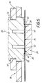
- stamp ring 20 with a series of stamps 24 formed, which are spaced apart. Laterally In addition to the stamping dies 24, the / each stamping ring 20 is also included Spacer rings 26 are formed, on each of which associated pressure roller 28 (see FIG. 5). To everybody the two spacer rings 26 are laterally integrally included Side section 30. Each of the two side sections 30 has a circumferential annular groove 32 trained to lay down an associated side cover 34 is provided.
- Heat insulating part 36 Between adjacent dies 24 and the two lateral spacer rings 26 is one Heat insulating part 36 arranged. In Figure 3 is one of these Heat insulating parts 36 indicated by hatching. The Heat insulating parts 36 are for example between the screwed two spacer rings 26, what with Reference numbers 38 is clarified.
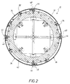
- Embossing roller 10 From the outer jacket 42 of the central carrier roller 12 Embossing roller 10 are - as can be seen from Figure 2 - four elongated strip elements 44 away, the side next to the stamp rings 20 are formed with suction openings 46, as Figure 1 shows.
- the elongated last elements 44 also have stop ribs 48 (see FIG. 2), the are provided laterally next to the stamp rings 20 and project radially beyond the stamp rings 20.
- the Stop ribs 48 are used to precisely define the respective leading edge of a sheet or arcuate substrate.
Applications Claiming Priority (3)
| Application Number | Priority Date | Filing Date | Title |
|---|---|---|---|
| DE19523441A DE19523441A1 (de) | 1995-06-28 | 1995-06-28 | Prägewalze für eine Prägevorrichtung |
| DE19523441 | 1995-06-28 | ||
| PCT/DE1996/000649 WO1997001442A1 (de) | 1995-06-28 | 1996-04-06 | Prägewalze für eine prägevorrichtung |
Publications (2)
| Publication Number | Publication Date |
|---|---|
| EP0835181A1 EP0835181A1 (de) | 1998-04-15 |
| EP0835181B1 true EP0835181B1 (de) | 1999-12-22 |
Family
ID=7765428
Family Applications (1)
| Application Number | Title | Priority Date | Filing Date |
|---|---|---|---|
| EP96909045A Expired - Lifetime EP0835181B1 (de) | 1995-06-28 | 1996-04-06 | Prägewalze für eine Prägevorrichtung |
Country Status (17)
| Country | Link |
|---|---|
| US (1) | US5937759A (no) |
| EP (1) | EP0835181B1 (no) |
| JP (1) | JP3095081B2 (no) |
| KR (1) | KR100329986B1 (no) |
| CN (1) | CN1077504C (no) |
| AT (1) | ATE187927T1 (no) |
| AU (1) | AU693680B2 (no) |
| BG (1) | BG62799B1 (no) |
| BR (1) | BR9608948A (no) |
| CA (1) | CA2224815C (no) |
| CZ (1) | CZ285936B6 (no) |
| DE (3) | DE19523441A1 (no) |
| ES (1) | ES2140836T3 (no) |
| NO (1) | NO310336B1 (no) |
| NZ (1) | NZ304826A (no) |
| TW (1) | TW330858B (no) |
| WO (1) | WO1997001442A1 (no) |
Families Citing this family (16)
| Publication number | Priority date | Publication date | Assignee | Title |
|---|---|---|---|---|
| US6694872B1 (en) | 1999-06-18 | 2004-02-24 | Holographic Label Converting, Inc. | In-line microembossing, laminating, printing, and diecutting |
| US6694873B1 (en) * | 1999-06-18 | 2004-02-24 | Holographic Label Converting, Inc. | Microembosser for faster production of holographic labels |
| KR20030087670A (ko) * | 2002-05-09 | 2003-11-15 | (주)다사테크 | 회전기계의 비접촉식 전원공급장치 |
| TWI253389B (en) * | 2003-07-25 | 2006-04-21 | Bobst Sa | Method for tightening an embossing plate ring on a chuck |
| EP1588865A1 (en) * | 2004-04-22 | 2005-10-26 | Kba-Giori S.A. | Embossing cylinder |
| EP1837202B1 (de) | 2006-03-21 | 2013-02-27 | Hueck Folien Ges.m.b.H. | Herstellverfahren für einen nahtlosen Prägezylinder |
| EP1961578A1 (en) | 2007-02-26 | 2008-08-27 | Kba-Giori S.A. | Method and installation for applying foil material onto successive sheets |
| EP2100736A1 (en) | 2008-03-14 | 2009-09-16 | Kba-Giori S.A. | Method and installation for applying foil material onto successive sheets |
| DE102008019720A1 (de) * | 2008-04-18 | 2009-10-22 | Leonhard Kurz Stiftung & Co. Kg | Beheizte Prägewalze |
| EP2141027A1 (en) | 2008-07-03 | 2010-01-06 | Kba-Giori S.A. | Method and installation for applying foil material onto successive sheets |
| EP2275259A1 (de) * | 2009-07-14 | 2011-01-19 | Pantec GS Systems AG | Druck- oder Prägewerk und Arbeitszylinder hierfür |
| CN102837496B (zh) * | 2012-09-24 | 2015-05-27 | 武汉虹之彩包装印刷有限公司 | 在同一压印辊上多次烫金的装置 |
| WO2014115086A2 (en) | 2013-01-22 | 2014-07-31 | Unilin, Bvba | Method and device for manufacturing products having a surface provided with embossments, and products obtained thereby |
| ES2861159T3 (es) * | 2014-07-31 | 2021-10-05 | Unilin Bv | Método para fabricar un producto de revestimiento de suelos |
| CN104191835B (zh) * | 2014-08-22 | 2017-05-03 | 上海应用技术学院 | 系列大型高速辊筒机械制造工艺 |
| DE102022003846A1 (de) | 2022-10-17 | 2024-04-18 | Hosokawa Alpine Aktiengesellschaft | Vorrichtung zum Recken von Folienbahnen in Maschinenrichtung mit Schnellwechselvorrichtung für Walzen sowie Verfahren dafür |
Family Cites Families (12)
| Publication number | Priority date | Publication date | Assignee | Title |
|---|---|---|---|---|
| DE233239C (no) * | ||||
| CH277336A (de) * | 1948-09-07 | 1951-08-31 | Semperit Ag | Einrichtung an Prägepressen zur Verhinderung des Wärmeüberganges von den geheizten Prägeplatten auf die anschliessenden Pressenteile. |
| CH322275A (de) * | 1954-03-03 | 1957-06-15 | Druckmaschinenwerk Victoria Ve | Prägedruckmaschine, insbesondere für Wertpapiere, Banknoten usw. |
| US3217637A (en) * | 1964-03-06 | 1965-11-16 | Gottscho Inc Adolph | Hot roll leaf stamping apparatus |
| US3590452A (en) * | 1969-01-09 | 1971-07-06 | Dayco Corp | Roller applicator device |
| US3693544A (en) * | 1970-04-02 | 1972-09-26 | Charles J Trzyna | Printout drum |
| DE2753296C2 (de) * | 1977-11-30 | 1982-04-15 | M.A.N. Maschinenfabrik Augsburg-Nürnberg AG, 8900 Augsburg | Schmitzringanordnung zwischen zwei Druckwerkszylindern |
| DE8518933U1 (de) * | 1985-06-29 | 1985-08-14 | Dornbusch, Paul, Dr., 4150 Krefeld | Prägewalze |
| US4917103A (en) * | 1985-09-18 | 1990-04-17 | C. R. Bard, Inc. | Guide wire extension |
| DE4024537C1 (no) * | 1990-08-02 | 1991-05-02 | Leonhard Kurz Gmbh & Co, 8510 Fuerth, De | |
| CA2149247C (en) * | 1992-12-14 | 2005-09-20 | Reinwald Mitsam | Process and device for transferring prints from a support to a substrate |
| FR2726786A1 (fr) * | 1994-11-14 | 1996-05-15 | Francille Jean | Agencement et manchon intercalaire porte-manchon mince notamment pour machine d'impression flexographique |
-
1995
- 1995-06-28 DE DE19523441A patent/DE19523441A1/de not_active Withdrawn
-
1996
- 1996-04-06 ES ES96909045T patent/ES2140836T3/es not_active Expired - Lifetime
- 1996-04-06 WO PCT/DE1996/000649 patent/WO1997001442A1/de active IP Right Grant
- 1996-04-06 KR KR1019970709972A patent/KR100329986B1/ko not_active IP Right Cessation
- 1996-04-06 US US08/981,136 patent/US5937759A/en not_active Expired - Lifetime
- 1996-04-06 DE DE59603987T patent/DE59603987D1/de not_active Expired - Lifetime
- 1996-04-06 JP JP09504076A patent/JP3095081B2/ja not_active Expired - Fee Related
- 1996-04-06 AU AU52699/96A patent/AU693680B2/en not_active Ceased
- 1996-04-06 NZ NZ304826A patent/NZ304826A/xx unknown
- 1996-04-06 DE DE19680498T patent/DE19680498D2/de not_active Expired - Fee Related
- 1996-04-06 AT AT96909045T patent/ATE187927T1/de not_active IP Right Cessation
- 1996-04-06 BR BR9608948A patent/BR9608948A/pt not_active IP Right Cessation
- 1996-04-06 CN CN96195130A patent/CN1077504C/zh not_active Expired - Fee Related
- 1996-04-06 CA CA002224815A patent/CA2224815C/en not_active Expired - Fee Related
- 1996-04-06 EP EP96909045A patent/EP0835181B1/de not_active Expired - Lifetime
- 1996-04-06 CZ CZ974154A patent/CZ285936B6/cs not_active IP Right Cessation
- 1996-04-30 TW TW085105126A patent/TW330858B/zh not_active IP Right Cessation
-
1997
- 1997-12-11 NO NO19975825A patent/NO310336B1/no unknown
- 1997-12-18 BG BG102128A patent/BG62799B1/bg unknown
Also Published As
| Publication number | Publication date |
|---|---|
| BG62799B1 (bg) | 2000-08-31 |
| NO975825L (no) | 1997-12-16 |
| TW330858B (en) | 1998-05-01 |
| DE19523441A1 (de) | 1997-01-02 |
| JP3095081B2 (ja) | 2000-10-03 |
| ES2140836T3 (es) | 2000-03-01 |
| JPH11509144A (ja) | 1999-08-17 |
| US5937759A (en) | 1999-08-17 |
| CN1189128A (zh) | 1998-07-29 |
| KR19990028650A (ko) | 1999-04-15 |
| CZ415497A3 (cs) | 1998-08-12 |
| WO1997001442A1 (de) | 1997-01-16 |
| ATE187927T1 (de) | 2000-01-15 |
| CA2224815C (en) | 2004-09-14 |
| BG102128A (en) | 1998-07-31 |
| NO975825D0 (no) | 1997-12-11 |
| CZ285936B6 (cs) | 1999-11-17 |
| KR100329986B1 (ko) | 2002-08-27 |
| NO310336B1 (no) | 2001-06-25 |
| CA2224815A1 (en) | 1997-01-16 |
| BR9608948A (pt) | 1999-03-02 |
| EP0835181A1 (de) | 1998-04-15 |
| CN1077504C (zh) | 2002-01-09 |
| NZ304826A (en) | 1999-02-25 |
| AU693680B2 (en) | 1998-07-02 |
| DE19680498D2 (de) | 1998-07-23 |
| AU5269996A (en) | 1997-01-30 |
| DE59603987D1 (de) | 2000-01-27 |
Similar Documents
| Publication | Publication Date | Title |
|---|---|---|
| EP0835181B1 (de) | Prägewalze für eine Prägevorrichtung | |
| DE3210551C2 (de) | Verfahren und Vorrichtung zum Anbringen eines Prägefolien-Abdruckes auf einer flexiblen Materialbahn | |
| EP0673317B1 (de) | Verfahren und vorrichtung zum übertragen von abdrucken von einem träger auf ein substrat | |
| DE112012006348B4 (de) | Kombinationsdruckvorrichtung | |
| EP0130452B1 (de) | Walzenfixiervorrichtung mit einer Andruckwalze und einer von innen beheizten Fixierwalze | |
| DE4325725C2 (de) | Verfahren und Vorrichtung zum Aufwickeln von im Rollen-Offsetdruck bedruckten Folienbahnen | |
| EP2275259A1 (de) | Druck- oder Prägewerk und Arbeitszylinder hierfür | |
| DE3835302A1 (de) | Drehschneidgesenk- und lamellierungsverfahren und vorrichtung zur durchfuehrung | |
| WO2005049322A1 (de) | Verfahren und vorrichtung zum kombinationsdruck | |
| EP2551114B1 (de) | Induktiv beheizbarer Zylinder mit Prägewerkzeug | |
| DE3533735C2 (no) | ||
| EP0687553A2 (de) | Maschine zur Herstellung einer einseitig kaschierten Wellpappebahn | |
| EP1309445A1 (de) | Verfahren zum positionieren einer patrize an einer gegendruckwalze einer prägestation | |
| DE4025712C1 (no) | ||
| EP0518053B1 (de) | Verfahren zur Herstellung bedruckter Wellpappe in grosser Arbeitsbreite sowie Anlage zur Durchführung des Verfahrens | |
| DE19543099C2 (de) | Verfahren und Vorrichtung zum Übertragen eines Druckbildes von einer Trägerbahn auf ein Substrat | |
| DE10159661C1 (de) | Heißprägemaschine mit einer Prägestation | |
| DE4024537C1 (no) | ||
| DE10301587A1 (de) | Verfahren und Transporteinrichtung zum Vorfixieren von Toner auf einem Bedruckstoff | |
| DE19953724C2 (de) | Präge-Rotationsmaschine | |
| DE1919992B1 (de) | Druckmaschine zum Heisspraegedruck mit absatzweise ueber erhitzte Praegestempel transportierte Farbfolien | |
| EP1129952B1 (de) | Verfahren und Vorrichtung zum Anbringen von Abziehbildern auf Behältern | |
| DE2144673A1 (de) | Verfahren und Vorrichtung zum Her stellen von bedruckten Kunststoffbehaltern | |
| CH700255B1 (de) | Druck- oder Prägewerk und Arbeitszylinder hierfür. | |
| EP0386316A1 (de) | Verfahren zur Herstellung einer Matrizenhülse und Vorrichtung zur Durchführung des Verfahrens |
Legal Events
| Date | Code | Title | Description |
|---|---|---|---|
| PUAI | Public reference made under article 153(3) epc to a published international application that has entered the european phase |
Free format text: ORIGINAL CODE: 0009012 |
|
| 17P | Request for examination filed |
Effective date: 19971121 |
|
| AK | Designated contracting states |
Kind code of ref document: A1 Designated state(s): AT CH DE DK ES FI LI SE |
|
| 17Q | First examination report despatched |
Effective date: 19980515 |
|
| GRAG | Despatch of communication of intention to grant |
Free format text: ORIGINAL CODE: EPIDOS AGRA |
|
| GRAG | Despatch of communication of intention to grant |
Free format text: ORIGINAL CODE: EPIDOS AGRA |
|
| GRAH | Despatch of communication of intention to grant a patent |
Free format text: ORIGINAL CODE: EPIDOS IGRA |
|
| RAP1 | Party data changed (applicant data changed or rights of an application transferred) |
Owner name: KOENIG & BAUER AKTIENGESELLSCHAFT Owner name: LEONHARD KURZ GMBH & CO. |
|
| GRAH | Despatch of communication of intention to grant a patent |
Free format text: ORIGINAL CODE: EPIDOS IGRA |
|
| GRAA | (expected) grant |
Free format text: ORIGINAL CODE: 0009210 |
|
| AK | Designated contracting states |
Kind code of ref document: B1 Designated state(s): AT CH DE DK ES FI LI SE |
|
| REF | Corresponds to: |
Ref document number: 187927 Country of ref document: AT Date of ref document: 20000115 Kind code of ref document: T |
|
| REG | Reference to a national code |
Ref country code: CH Ref legal event code: NV Representative=s name: FIAMMENGHI-FIAMMENGHI Ref country code: CH Ref legal event code: EP |
|
| REF | Corresponds to: |
Ref document number: 59603987 Country of ref document: DE Date of ref document: 20000127 |
|
| REG | Reference to a national code |
Ref country code: ES Ref legal event code: FG2A Ref document number: 2140836 Country of ref document: ES Kind code of ref document: T3 |
|
| PG25 | Lapsed in a contracting state [announced via postgrant information from national office to epo] |
Ref country code: DK Free format text: LAPSE BECAUSE OF FAILURE TO SUBMIT A TRANSLATION OF THE DESCRIPTION OR TO PAY THE FEE WITHIN THE PRESCRIBED TIME-LIMIT Effective date: 20000322 |
|
| PLBE | No opposition filed within time limit |
Free format text: ORIGINAL CODE: 0009261 |
|
| STAA | Information on the status of an ep patent application or granted ep patent |
Free format text: STATUS: NO OPPOSITION FILED WITHIN TIME LIMIT |
|
| 26N | No opposition filed | ||
| PGFP | Annual fee paid to national office [announced via postgrant information from national office to epo] |
Ref country code: ES Payment date: 20080424 Year of fee payment: 13 |
|
| PGFP | Annual fee paid to national office [announced via postgrant information from national office to epo] |
Ref country code: AT Payment date: 20080423 Year of fee payment: 13 |
|
| PGFP | Annual fee paid to national office [announced via postgrant information from national office to epo] |
Ref country code: FI Payment date: 20080422 Year of fee payment: 13 |
|
| PGFP | Annual fee paid to national office [announced via postgrant information from national office to epo] |
Ref country code: SE Payment date: 20080424 Year of fee payment: 13 |
|
| EUG | Se: european patent has lapsed | ||
| PG25 | Lapsed in a contracting state [announced via postgrant information from national office to epo] |
Ref country code: FI Free format text: LAPSE BECAUSE OF NON-PAYMENT OF DUE FEES Effective date: 20090406 Ref country code: AT Free format text: LAPSE BECAUSE OF NON-PAYMENT OF DUE FEES Effective date: 20090406 |
|
| REG | Reference to a national code |
Ref country code: ES Ref legal event code: FD2A Effective date: 20090407 |
|
| PG25 | Lapsed in a contracting state [announced via postgrant information from national office to epo] |
Ref country code: ES Free format text: LAPSE BECAUSE OF NON-PAYMENT OF DUE FEES Effective date: 20090407 |
|
| PG25 | Lapsed in a contracting state [announced via postgrant information from national office to epo] |
Ref country code: SE Free format text: LAPSE BECAUSE OF NON-PAYMENT OF DUE FEES Effective date: 20090407 |
|
| PGFP | Annual fee paid to national office [announced via postgrant information from national office to epo] |
Ref country code: CH Payment date: 20140422 Year of fee payment: 19 Ref country code: DE Payment date: 20140409 Year of fee payment: 19 |
|
| REG | Reference to a national code |
Ref country code: DE Ref legal event code: R119 Ref document number: 59603987 Country of ref document: DE |
|
| REG | Reference to a national code |
Ref country code: CH Ref legal event code: PL |
|
| PG25 | Lapsed in a contracting state [announced via postgrant information from national office to epo] |
Ref country code: LI Free format text: LAPSE BECAUSE OF NON-PAYMENT OF DUE FEES Effective date: 20150430 Ref country code: CH Free format text: LAPSE BECAUSE OF NON-PAYMENT OF DUE FEES Effective date: 20150430 Ref country code: DE Free format text: LAPSE BECAUSE OF NON-PAYMENT OF DUE FEES Effective date: 20151103 |