EP0833501A2 - Circuit et procédé d'amélioration de la qualité d'image - Google Patents
Circuit et procédé d'amélioration de la qualité d'image Download PDFInfo
- Publication number
- EP0833501A2 EP0833501A2 EP97307183A EP97307183A EP0833501A2 EP 0833501 A2 EP0833501 A2 EP 0833501A2 EP 97307183 A EP97307183 A EP 97307183A EP 97307183 A EP97307183 A EP 97307183A EP 0833501 A2 EP0833501 A2 EP 0833501A2
- Authority
- EP
- European Patent Office
- Prior art keywords
- signal
- luminance signal
- colour
- output
- noise
- Prior art date
- Legal status (The legal status is an assumption and is not a legal conclusion. Google has not performed a legal analysis and makes no representation as to the accuracy of the status listed.)
- Withdrawn
Links
- 238000000034 method Methods 0.000 title claims abstract description 31
- 230000002708 enhancing effect Effects 0.000 claims abstract description 62
- 238000001914 filtration Methods 0.000 claims abstract description 10
- 239000003638 chemical reducing agent Substances 0.000 claims description 33
- 230000001186 cumulative effect Effects 0.000 claims description 27
- 230000008859 change Effects 0.000 claims description 17
- 238000012545 processing Methods 0.000 claims description 14
- 238000009966 trimming Methods 0.000 claims description 10
- 241000282414 Homo sapiens Species 0.000 claims description 4
- 230000006870 function Effects 0.000 description 85
- 239000003623 enhancer Substances 0.000 description 19
- 238000013507 mapping Methods 0.000 description 19
- 230000009467 reduction Effects 0.000 description 19
- 238000010586 diagram Methods 0.000 description 15
- 238000012937 correction Methods 0.000 description 9
- 230000015556 catabolic process Effects 0.000 description 5
- 238000006731 degradation reaction Methods 0.000 description 5
- 230000001360 synchronised effect Effects 0.000 description 4
- 230000003044 adaptive effect Effects 0.000 description 3
- 239000003086 colorant Substances 0.000 description 3
- 238000001514 detection method Methods 0.000 description 3
- 230000000694 effects Effects 0.000 description 3
- 230000008569 process Effects 0.000 description 3
- 238000000926 separation method Methods 0.000 description 3
- 230000001934 delay Effects 0.000 description 2
- 238000013459 approach Methods 0.000 description 1
- 238000006243 chemical reaction Methods 0.000 description 1
- 230000007423 decrease Effects 0.000 description 1
- 230000007547 defect Effects 0.000 description 1
- 230000003111 delayed effect Effects 0.000 description 1
- 238000002059 diagnostic imaging Methods 0.000 description 1
- 230000009977 dual effect Effects 0.000 description 1
- 238000011156 evaluation Methods 0.000 description 1
- 238000007689 inspection Methods 0.000 description 1
- 238000003672 processing method Methods 0.000 description 1
- 230000004044 response Effects 0.000 description 1
- 229920006395 saturated elastomer Polymers 0.000 description 1
Images


Classifications
-
- H—ELECTRICITY
- H04—ELECTRIC COMMUNICATION TECHNIQUE
- H04N—PICTORIAL COMMUNICATION, e.g. TELEVISION
- H04N5/00—Details of television systems
- H04N5/14—Picture signal circuitry for video frequency region
- H04N5/20—Circuitry for controlling amplitude response
- H04N5/202—Gamma control
-
- H—ELECTRICITY
- H04—ELECTRIC COMMUNICATION TECHNIQUE
- H04N—PICTORIAL COMMUNICATION, e.g. TELEVISION
- H04N9/00—Details of colour television systems
- H04N9/64—Circuits for processing colour signals
- H04N9/68—Circuits for processing colour signals for controlling the amplitude of colour signals, e.g. automatic chroma control circuits
-
- H—ELECTRICITY
- H04—ELECTRIC COMMUNICATION TECHNIQUE
- H04N—PICTORIAL COMMUNICATION, e.g. TELEVISION
- H04N1/00—Scanning, transmission or reproduction of documents or the like, e.g. facsimile transmission; Details thereof
- H04N1/46—Colour picture communication systems
- H04N1/56—Processing of colour picture signals
- H04N1/58—Edge or detail enhancement; Noise or error suppression, e.g. colour misregistration correction
-
- H—ELECTRICITY
- H04—ELECTRIC COMMUNICATION TECHNIQUE
- H04N—PICTORIAL COMMUNICATION, e.g. TELEVISION
- H04N9/00—Details of colour television systems
- H04N9/64—Circuits for processing colour signals
- H04N9/646—Circuits for processing colour signals for image enhancement, e.g. vertical detail restoration, cross-colour elimination, contour correction, chrominance trapping filters
Definitions
- the present invention relates to image quality enhancement, and more particularly, to an image quality enhancing circuit having functions such as noise reduction, contrast enhancement based on histogram equalization, local contrast enhancement and colour compensation and a method therefor.
- the image quality of a video signal can be deteriorated due to various factors.
- a low contrast can be a factor among representative ones of image quality degradation.
- As a method for correcting the image quality degradation there are gamma correction for making a correction according to a variation in brightness, histogram equalization, etc.
- the principal operation of the histogram equalization is to convert a given input image on the basis of the histogram of the input image.
- the histogram represents gray level distribution at a given input image.
- Such a histogram of the gray level provides an entire depiction on the appearance of an image.
- a gray level appropriately adjusted according to sample distribution of an image enhances the appearance and contrast of the image.
- the histogram equalization for enhancing the contrast of a given image according to sample distribution of the image is the most widely known among various contrast enhancing methods, which is disclosed in the following documents: [1] J.S.Lim, "Two-Dimensional Signal and Image Processing,” Prentice Hall, Englewood Cliffs, New Jersey, 1990; and [2] R.C.Gonzalez and P.Wints, "Digital Image Processing,” Addison-Wesley, Reading, Massachusetts, 1977.
- histogram equalization since histogram equalization has the effect of stretching a dynamic range, it flattens distribution density of a resultant image. Therefore, the contrast of the image is enhanced.
- Such a well-known characteristic of the histogram equalization becomes a defect in some actual cases. That is, because of this characteristic of the histogram equalization flattening an output density, the average brightness of the output image approaches to a middle gray level.
- the average brightness of an output image in the histogram equalization is exactly the middle gray level regardless of the average brightness of an input image.
- the above-described characteristic is not desirable for the practical application. For example, a problem that a scene photographed at night looks too bright after the histogram equalization is generated.
- Still another factor of the image quality degradation is that the gamma correction or the histogram equalization for enhancing a low contrast enhances an entire contrast of a video signal but is not so effective for enhancement of a contrast at detailed portions being visually more important information, i.e., a local contrast.
- Yet another factor of the image quality degradation is that, unless colour compensation is performed on a colour signal according to a variation in luminance occurring when a predetermined luminance processing such as the histogram equalization is performed on a luminance signal to enhance a contrast, a primary colour signal is distorted.
- an image quality enhancing circuit having such functions as noise reduction, contrast enhancement based on mean-separation histogram equalization, local contrast enhancement, and colour compensation.
- the present invention provides, a noise reducing means of an image quality enhancing circuit detects an impulse for each of an input luminance signal and input colour signals and outputs a trimmed mean of a predetermined size window when the impulse is detected, and otherwise, bypasses the input signals without change.
- a contrast enhancing means independently equalizes a luminance signal of a picture unit output by the noise reducer by obtaining a histogram of subimages divided on the basis of the mean value of the luminance signal and outputs an enhanced luminance signal.
- a local contrast enhancing means detects a local contrast defined as a difference between the value of an input sample with respect to the enhanced luminance signal and each value obtained by low-pass filtering samples in a predetermined size window including the input sample, adaptively weights the input sample value according to the detected local contrast, and outputs a changed luminance signal. Also, a colour compensating means compensates the colour signals output by the noise reducing means according to the changed luminance signal.
- an image quality enhancing circuit for enhancing image quality through a predetermined image processing on an input image signal, said circuit comprising: noise reducing means for detecting an impulse for each of an input luminance signal and input colour signals and outputting a trimmed mean of a predetermined size window when said impulse is detected, and otherwise, bypassing said input signals without change; contrast enhancing means for equalizing a luminance signal of a picture unit output by said noise reducing means and outputting an enhanced luminance signal; local contrast enhancing means for detecting a local contrast defined as a difference between the value of an input sample with respect to said enhanced luminance signal and each value obtained by low-pass filtering samples in a predetermined size window including the input sample, adaptively weighting said input sample value according to said detected local contrast, and outputting a changed luminance signal; and colour compensating means for compensating said colour signals output by said noise reducing means according to said changed luminance signal.
- the image quality enhancing circuit further comprises: a first colour converter for converting an input RGB signal into a luminance signal and colour signals and outputting the result to said noise reducing means; and a second colour converter for outputting said luminance signal output by said local contrast enhancing means and said compensated colour signal output by said colour compensating means in RGB form.
- Said first colour converter preferably converts said input RGB signal into one of signals (Y, U, V) and (Y, I, Q).
- Said noise reducing means preferably comprises a plurality of noise reducers for reducing impulse noise for said luminance signal and said colour signals, respectively.
- Said noise reducing means may comprise: a first noise reducer for reducing impulse noise included in the input luminance signal; a selector for selecting a signal from two input colour signals; a second noise reducer for reducing impulse noise included in the colour signal selected by said selector; and a separator for separating the colour signal whose noise is reduced by said second noise reducer into two types of colour signals.
- Each of said noise reducers may comprise: a window generator for generating a plurality of different-sized windows including an input signal; a plurality of outlier value detectors for detecting a mean between a mean sample value for each window and an absolute deviation of samples and detecting whether an input signal has an outlier value; a selection control signal generator for generating a selection control signal when all of said input signals are detected to be outlier values in said plurality of outlier value detectors; a trimmed mean filter for trimming an input signal using a trimming window of a predetermined size and outputting a trimmed mean; and a selector for outputting said trimmed mean as an output signal when an impulse component exists in said input signal according to said selection control signal and, otherwise, outputting said input signal as an output signal without change.
- Said window generator may substitute said input signal for an output signal in a recursive noise reduction mode according to a recursive/nonrecursive noise reduction mode signal and then generates a plurality of windows for a next input signal.
- Said window generator may generate first and second windows each having a different size and including the input signal.
- Said plurality of outlier value detectors preferably comprise: a first outlier value detector for judging an impulse component to be included in an input signal when an absolute difference between the input signal and a mean sample value of said first window is greater than the mean of an absolute deviation of said first window multiplied by a parameter for predetermined noise reduction, and outputting a first outlier value detecting signal; and a second outlier value detector for judging an impulse component to be included in an input signal when an absolute difference between the input signal and a mean sample value of said second window is greater than the mean of an absolute deviation of said second window multiplied by the parameter for predetermined noise reduction, and outputting a second outlier value detecting signal.
- Said trimming window preferably uses one window among said plurality of windows.
- Said contrast enhancing means is preferably comprised of a mean-separate histogram equalizer for independently equalizing a luminance signal of a picture unit output by said noise reducing means by obtaining a histogram of subimages divided on the basis of the mean value of said luminance signal.
- Said contrast enhancing means may comprise: first calculating means for receiving a noise-removed luminance signal output by said noise reducing means, in a picture unit, and calculating the distribution of a gray level; second calculating means for receiving said noise-reduced luminance signal in a picture unit and calculating a mean level; third calculating means for dividing said gray level distribution of the calculated picture unit into a predetermined number of subimages according to said mean level and calculating a cumulative density function for each subimage; and mapping means for mapping said noise-reduced luminance signal to a gray level according to said cumulative density function value calculated by each of said subimages and outputting an enhanced luminance signal.
- Said picture unit is preferably a frame unit and said predetermined number is two.
- a frame memory is provided for delaying said noise-reduced luminance signal in a frame unit in order to input a signal of the same frame as said cumulative density function calculated by said third calculating means to said mapping means.
- a buffer may be provided for renewing said cumulative density function calculated by said third calculating means in a picture unit and providing the cumulative density function value stored during the renewal to said mapping means.
- Said mapping means may comprise: a first mapper for mapping said noise-reduced luminance signal to a gray level having a first range according to a corresponding cumulative density function value when said noise-reduced luminance signal is a first subimage lower than or equal to the mean level; a second mapper for mapping said noise-reduced luminance signal to a gray level having a second range according to a corresponding cumulative density function value when said noise-reduced luminance signal is a second subimage greater than said mean level; a comparator for comparing said noise-reduced luminance signal with said mean level and generating a selection control signal; and a selector for selecting said first mapper when said noise-reduced luminance signal is said first subimage according to said selection control signal, and otherwise, selecting said second mapper.
- Said mapping means may comprise: a first mapper for mapping the luminance signal output by said frame memory to a gray level having a first range according to a corresponding cumulative density function value when said luminance signal output by said frame memory is a first subimage lower than or equal to the mean level; a second mapper for mapping said luminance signal output by said frame memory to a gray level having a second range according to a corresponding cumulative density function value when said luminance signal output by said frame memory is a second subimage greater than said mean level; a comparator for comparing said luminance signal output by said frame memory with said mean level and generating a selection control signal; and a selector for selecting said first mapper when said luminance signal output by said frame memory is said first subimage according to said selection control signal, and otherwise, selecting said second mapper.
- Said contrast enhancing means preferably further comprises brightness compensating means for outputting a compensated mean level by adding a corrected value depending on a predetermined correction function to said mean level.
- Said brightness compensating means preferably outputs a compensated mean level by adding a corrected value greater than zero to said mean level when said mean level is very small and by adding a corrected value lower than zero when said mean level is very large.
- Said mapping means may comprise: a first mapper for mapping said noise-reduced luminance signal to a gray level from a minimum gray level to a compensated mean level (B m ) according to the cumulative density function value of a corresponding subimage when said noise-reduced luminance signal is lower than or equal to said mean level; a second mapper for mapping said luminance signal to a gray level from a changed compensated mean level (B m ') to a maximum gray level (X L-1 ) according to the cumulative density function value of a corresponding subimage when said luminance signal is greater than said mean level, wherein B m ' equals B m +X L-1 /(L-1); a comparator for comparing said noise-reduced luminance signal with said mean level and generating a selection control signal; and a selector for selecting said first mapper when said noise-reduced luminance signal is said first subimage according to said selection control signal, and otherwise, selecting said second mapper.
- Said contrast enhancing means may further comprise gain control means for controlling the gain of said enhanced luminance signal according to an amount of variation in gray level between said noise-reduced luminance signal and said enhanced luminance signal and the level of said noise-reduced luminance signal.
- Said gain control means may control the gain of said enhanced luminance signal on the basis of a Weber ratio.
- Said gain control means may comprise: a subtracter for subtracting said noise-reduced luminance signal from said enhanced luminance signal and detecting a variation amount corresponding to the difference; a gain feature determiner for calculating a maximum bounding function value according to the level of said noise-reduced luminance signal to restrict enhancement of said noise-reduced luminance signal using a predetermined maximum bounding function; a multiplier for multiplying said maximum bounding function value by a gain control parameter having a predetermined value and outputting a bounding function value; a limiter for comparing said bounding function value with said variation amount, limiting said variation amount according to the compared result, and outputting a limited variation amount; and an adder for adding said limited variation amount to said noise-reduced luminance signal.
- Said gain control means may further comprise a selector arranged to compare said noise-reduced luminance signal with said mean level and select the gain control parameter to be a first gain control parameter when said noise-reduced luminance signal is lower than or equal to said mean level and, otherwise, to select the gain control parameter to be a second gain control parameter.
- Said maximum bounding function g(X k ) is preferably aX k and a may be a constant or said maximum bounding function g(X k ) may be a X k where a is a constant.
- said limiter outputs said variation amount as said limited variation amount when an absolute value of said variation amount is lower than or equal to said bounding function value, and otherwise, outputs said bounding function value as said limited variation amount.
- Said local contrast enhancing means may comprise: a window generator for generating an input sample with respect to an enhanced luminance signal output by said contrast enhancing means generating a predetermined-sized window including said input sample; a low-pass filter for low-pass filtering the samples of said window generated by said window generator and outputting a low-pass filtered signal; a subtracter for subtracting said low-pass filtered signal from the input sample output by said window generator and generating a local contrast signal corresponding to a contrast which can be visually perceived by a human being; an absolute value calculator for calculating an absolute value of said local contrast signal and detecting a region having high or low contrast; a weighting unit for adding a weighted value obtained by a predetermined weighting function to the output of said absolute value calculator; a first multiplier for multiplying the output of said weighter by a parameter for controlling an amount of local contrast enhancement; a second multiplier for multiplying said local contrast signal by the output of said first multiplier; and an adder for adding the output of said second multiplier to the input sample
- Said weighting function preferably enhances said local contrast signal when the absolute value of said local contrast signal is lower than a predetermined value and bypasses said local contrast signal without enhancement when the absolute value of said local contrast signal is greater than or equal to the predetermined value.
- Said colour compensating means may comprise: an operator for operating a ratio between the luminance signal output by said noise reducing means and the changed luminance signal output by said local contrast enhancing means; and multipliers for multiplying the colour signals output by said noise reducing means by the ratio output by said operator and outputting compensated colour signals.
- Said colour compensating means may comprise: an operator for operating a ratio between the luminance signal output by said noise reducing means and the changed luminance signal output by said local contrast enhancing means; and regulators for receiving the colour signals output by said noise reducing means, the ratio output by said operator, and a predetermined parameter and outputting compensated colour signals by changing the value of the colour signals using a predetermined compensating line.
- an image quality enhancing method for enhancing the image quality of an input image signal by performing a predetermined image processing on said input image signal, said method comprising the steps of: (a) detecting an impulse for each of input luminance and colour signals, outputting a trimmed mean of a predetermined- sized window when said impulse is detected, and bypassing said input signals when said impulse is not detected, thereby outputting noise-reduced luminance and colour signals; (b) receiving said noise-reduced luminance signal in a picture unit, equalizing said noise-reduced luminance signal, and outputting an enhanced luminance signal; (c) detecting a local contrast defined as a difference between an input sample value with respect to said enhanced luminance signal and each value obtained by low-pass filtering samples of a predetermined-sized window including the input sample, and outputting a luminance signal changed by adaptively weighting the input sample value according to said detected local contrast; and (d) compensating said noise-reduced colour signals according to said changed luminance signal
- the method preferably further comprises the steps of: (el) converting input RGB signals into a luminance signal and colour signals and outputting the result before said step (a) ; and (e2) converting and outputting said changed luminance signal and said compensated colour signal in RGB signal form after said step (d).
- Said RGB signal received in step (el) is preferably converted into one of signals (Y, U, V), (Y, R-Y, B-Y) and (Y, I, Q).
- Said step (a) may comprise the substeps of: (al) generating a plurality of windows of different sizes including the input signal; (a2) obtaining a mean sample value for each of said windows and a mean of an absolute deviation between samples; (a3) detecting whether or not an impulse component exists in the input signal, using said obtained mean sample value of each window and said means of the absolute deviation between samples; and (a4) outputting a trimmed mean by trimming the samples in a predetermined-sized trimming window when an impulse component is detected from said input signal, and otherwise, bypassing said input signal.
- step (a3) When said impulse component is detected from said input signal in at least two windows in step (a3), it is preferably judged that said impulse component exists in said input signal.
- Said trimming window may be one of said plurality of windows.
- Said step (a) may further comprise the step of (a5) replacing said input signal with said output signal, moving it to a next input signal, and returning to step (a1).
- Said step (b) preferably comprises the substeps of: (bl) receiving said noise-reduced luminance signal in a picture unit and calculating a mean level; (b2) calculating a cumulative density function, based on gray level distribution, for every subimage divided on the basis of said calculated mean level; and (b3) outputting an enhanced luminance signal by performing independent histogram equalization with respect to each subimage on the basis of said cumulative density function value obtained for each of said subimages.
- Said noise-reduced luminance signal of a picture unit is preferably divided into two subimages according to said mean level, in step (b2).
- Said step (b3) may comprise the substeps of: (b31) mapping the samples for each subimage to a gray level according to said cumulative density function value obtained for every subimage; and (b32) comparing the level of said noise-reduced luminance signal with said mean level and selecting one from said signals mapped to the gray level in each of said subimages, according to a compared result.
- the method may further comprise the step of (b33) delaying said noise-reduced luminance signal in a picture unit and outputting said delayed signal to step (b32).
- Said step (b) may further comprise the step of (b4) outputting a compensated mean level by adding a corrected value depending on a predetermined correcting function to said mean level.
- said compensated mean level is preferably output by adding a corrected value greater than zero to said mean level when said mean level is very small, and by adding a corrected value lower than zero to said mean level when said mean level is very large.
- Said step (b3) may comprise the substeps of: (b31') mapping said noise-reduced luminance signal to a gray level from a minimum gray level to a compensated mean level (B m ) according to the cumulative density function value of a corresponding subimage when said noise-reduced luminance signal is lower than or equal to said mean level; and (b32') mapping said luminance signal to a gray level from a changed compensated mean level (B m ') to a maximum gray level (X L-1 ) according to the accumulative density function value of a corresponding subimage when said luminance signal is greater than said mean level, wherein B m ' equals B m +X L-1 /(L-1).
- Said step (b) may comprise the step of (b5) controlling the gain of an enhanced signal according to an amount of gray level variation between said noise-reduced luminance signal and said enhanced luminance signal and the level of said noise-reduced luminance signal.
- Said gain control of said enhanced luminance signal is preferably based on a Weber ratio, in step (b5).
- Said step (b5) may comprise the substeps of: (b51) subtracting said luminance signal from said enhanced signal and detecting an amount of variation corresponding to the difference; (b52) calculating a limit enhancement amount of said luminance signal using a predetermined maximum bounding function and a predetermined gain control parameter; (b53) comparing said limit enhancement amount with said variation amount, limiting said variation amount according to the compared result, and outputting a limited variation amount; and (b54) adding said limited variation amount to said noise-reduced luminance signal.
- Said step (b52) may comprise the substeps of: (b521) calculating a maximum bounding function value according to the level of said noise-reduced luminance signal using a predetermined maximum bounding function in order to limit enhancement of said noise-reduced luminance signal; and (b522) multiplying said maximum bounding function value by a predetermined gain control parameter and outputting a limit enhancement amount.
- Said predetermined gain control parameter may comprise a plurality of gain control parameters for each divided subimage.
- Said predetermined gain control parameter may comprise a gain control parameter which is commonly applied to said noise-reduced luminance signal.
- Said maximum bounding function g(X k ) may be aX k where a is a constant or said maximum bounding function g(X k ) may be a X k and a is a constant.
- step (b53) said variation amount is preferably output as said limited variation amount when an absolute value of said variation amount is lower than or equal to said limit enhancement amount, and otherwise, said limit enhancement amount is output as said limited variation amount.
- Said step (c) preferably comprises the substeps of: (cl) detecting a local contrast corresponding to a difference between an input sample value with respect to said enhanced luminance signal and each value obtained by low-pass filtering the samples in a predetermined-sized window including an input sample; and (c2) adaptively weighting a weighted value depending on a predetermined weighting function to said input sample value according to said detected local contrast value.
- Said weighting function preferably enhances said local contrast value when said detected local contrast value is lower than a predetermined value and bypasses said local contrast value without enhancement when said detected local contrast value is greater than or equal to the predetermined value.
- Said compensated colour signal may be changed in the same direction as that of said noise-reduced colour signal, in step (d).
- said changed luminance signal preferably forms a luminance plane changed in a colour signal space, and luminance values of every colour signal in said formed luminance plane are the same.
- said compensated colour signal may be obtained by an intersecting point of a line linking the direction of said noise-reduced colour signal with the changed luminance plane.
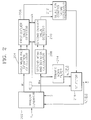
- a first colour converter 100 receives baseband digital colour signals indicated by R in , G in and B in and converts them into a digital luminance signal and system-defined colour signals which are indicated by Y in , U in and V in .
- R, G and B signals can be converted into various different colour signals like (Y, I, Q), (Y, U, V) and (Y, R-Y, B-Y) colour systems according to a signal processing method.
- the relationship between the R, G and B signals and new colour signals Y, U and V can be expressed by following equation 1.
- (Y,U,V) is defined by a colour system
- Y denotes a luminance signal
- U and V represent system-defined colour signals.
- a first function of an image quality enhancing circuit is to remove impulse noise.
- First to third noise reducers 200, 220 and 240 detect an outlier value based on statistics of samples and trim the result in order to remove impulse noise, respectively.
- the first to third noise reducers 200, 220 and 240 output the trimmed mean of a given window when an impulse has been detected from an input sample, otherwise, bypass the input sample.
- the detection failure can be an essential factor of blurring out details of a video signal.
- the degree of detection of an outlier value is determined by a parameter k.
- noise reducers 200, 220 and 240 having independent but identical configurations are employed to reduce impulse noises of the Y in , U in , and V in signals.
- a single noise reducer can be employed instead of the second and third noise reducers 220 and 240 for U in and V in signals.
- a multiplexer for selecting the U in or V in signals can be installed in front of the noise reduction block, and a demultiplexer for separating noise-reduced U in or V in signal can be provided in rear of the noise reduction block.
- a main function of the image quality enhancing circuit is to enhance a contrast using a contrast enhancer 300 based on mean-separate histogram equalization having gain control and brightness compensation (hereinafter, referred to as a contrast enhancer).
- a given image is divided into two individual groups on the basis of the mean value of the given image, and the divided sub-images are independently equalized.
- the proposed mean-separate histogram equalization is applied, an abrupt change in brightness and artifects, which can be generated after a general histogram equalization when an input image has a concentrated distributed histogram, can be effectively prevented. Also, the functions of gain control and brightness compensation can combine with the mean-separate histogram equalization. However, other embodiments of histogram equalization as well as the proposed mean-separate histogram equalization can be applied in the present invention.
- the brightness compensation can be simply carried out by mapping a current mean to a desired output mean during the mean-separate histogram equalization. Also, the gain control functions to prevent excess contrast enhancement by controlling the gain of a signal enhanced by the mean-separate histogram equalization depending on the level of an input signal.
- a local contrast enhancer 400 for sharpness enhancement detects a local contrast which is defined as a difference between an input sample value and a respective low-pass filtered sample values within a predetermined-size window including the input sample, and adaptively weights the input sample by applying a weight value depending on a weighting function to the local contrast according to the amplitude of the detected local contrast.
- a colour compensator 500 appropriately compensates for colour signals U and V output by the second and third noise reducers 220 and 240, according to a luminance signal Y output by the first noise reducer 200 and a changed luminance signal Y' output by the local contrast enhancer 400.
- the colour compensator 500 maps a current colour signal put on a given luminance plane to a colour signal obtained by moving in a colour direction until the colour signal intersects an enhanced luminance plane in a RGB space. Consequently, compensated colour signals U' and V' are output by changing the colour signals U and V by the same ratio as that of the change of the luminance signal.
- a second colour converter 600 receives the signal Y' output by the local contrast enhancer 400 and the U' and V' signals output by the colour compensator 500 and outputs R out , G out and B out signals through an inverse processing of the conversion performed by the first colour converter 100.
- the external parameters shown in Figure 1 are useful and characterize the entire function of the image quality enhancing circuit, which are a parameter (k) for noise reduction degree, a parameter (S) for selection of a recursive/nonrecursive noise reduction mode, gain control parameters ( ⁇ u , ⁇ L ) which are input to the contrast enhancer 300, a sharpness control parameter ( ⁇ ) which is input to the local contrast enhancer 400 and a colour control parameter ( ⁇ ) which is input to the colour compensator 500.
- k for noise reduction degree
- S for selection of a recursive/nonrecursive noise reduction mode
- gain control parameters ⁇ u , ⁇ L
- ⁇ sharpness control parameter
- ⁇ which is input to the local contrast enhancer 400
- ⁇ colour control parameter
- Figure 2 is a detailed block diagram of the first noise reducer 200 shown in Figure 1.
- the second and third noise reducers 220 and 240 have the same configurations, only the first noise reducer 200 for removing impulse noise of a Y in signal will be described.
- a window generator 202 outputs two windows expressed by the following equations, and a current input sample Y[i][j]. wherein, W L and W M are called as large and small windows, respectively. That is, L1 is greater than M1.
- 5 ⁇ 5 large window (W L ) and 3 ⁇ 3 small window (W M ) generated by the window generator 202 are as follows.
- 5X5 large window (W L ) and 3 ⁇ 3 small window (W M ) generated by the window generator 202 are as follows.
- Y N [ ][ ] denotes a signal output by the noise reducer 200 shown in Figure 2 according to the present invention, i.e., a filtered signal.
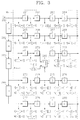
- the detailed circuit diagram of the window generator 202 is comprised of a plurality of sample delays 261 to 280, four line delays 281 to 284 and a multiplexer 285.
- the multiplexer 285 selects an input sample Y[i][j] upon the nonrecursive noise reduction mode and selects a final output signal Y N [i][j] output by a selector 216 upon the recursive noise reduction mode, according to the external recursive/nonrecursive noise reduction mode signal (S).
- D and H denote a sample delay and a line memory, respectively.
- a first mean and deviation calculator 204 receives samples of the large window (W L ) generated by the window generator 202, obtains a mean sample value (A L ) of the large window (W L ) using the following equation 8, and calculates the mean (D L ) of the absolute deviations of the samples of the large window (W L ) using the following equation 9.
- a first outlier value detector 206 outputs a first outlier value detecting signal by determining that an impulse component is included in the input sample Y[i][j], when an absolute difference between the input sample Y[i][j] and the mean sample value (A L ) of the large window (W L ) is greater than the mean (kD L ) of an absolute deviation multiplied by a predetermined parameter (k), i.e.,
- k denotes a noise reduction parameter.
- a second mean and deviation calculator 208 receives samples of the small window (W M ) generated by the window generator 202, obtains a mean sample value (A M ) of the small window (W M ) using the following equation 10, and calculates the mean (D M ) of the absolute deviations of the samples of the small window (W M ) using the following equation 11.
- a second outlier value detector 210 outputs a second outlier value detecting signal by determining that an impulse component is included in the input sample Y[i][j], when an absolute difference between the input sample Y[i][j] and the mean sample value (A M ) of the small window (W M ) is greater than the mean (kD M ) of an absolute deviation multiplied by the parameter (k), i.e., Y[i][j]-A M
- a selection control signal generator 212 generates a selection control signal for selecting the output of a trimmed mean filter 214 when the first and second outlier value detecting signals generated by the first and second outlier value detectors 206 and 210 are all generated, and, otherwise, bypassing the input sample without change.
- the trimmed mean filter 214 trims the sample of the small window W M generated by the window generator 202 using following equation 12, and outputs an output signal y tr [i][j] by taking the mean of residual samples.
- T M denotes the number of untrimmed samples or the number of samples which are not determined as outlier values.
- An embodiment of the present invention uses the small window as a trimming window, but the size of the trimming window is variable.
- FIG 4 is a detailed block diagram of the contrast enhancer 300 shown in Figure 1.
- a frame histogram calculator 302 receives a luminance signal (Y) output by the first noise reducer 200 shown in Figure 1 and calculates a histogram in units of one picture. That is, the distribution of the gray level of a frame image is calculated.
- the picture unit can be a field, but here is set to be a frame.
- an input image signal ⁇ Y ⁇ is comprised of L discrete levels represented by ⁇ X 0 ),X 1 ,...,X L-1 ⁇ .
- a frame mean calculator 304 calculates the mean level (X m ) of the luminance signal output by the first noise reducer 200 in units of frame. At this time, X m ⁇ ⁇ X 0 ,X 1 ,...,X L-1 ⁇ .
- a divider 306 divides the gray level distribution calculated by the frame histogram calculator 302 into the predetermined number (here, two) of subimages ⁇ X ⁇ L and ⁇ X ⁇ U on the basis of the mean level (X m ) calculated by the frame mean calculator 304, and outputs probability density functions p L (X k ) and p U (X k ) of two subimages.
- the probability density functions p L (X k ) and p U (X k ) can be calculated by following equations 13 and 14.
- L is the number of levels
- p L (X k ) is a probability of a k-th gray level (X k ) in the subimage ⁇ X ⁇ L
- p U (X k ) is a probability of a k-th gray level (X k ) in the subimage ⁇ X ⁇ U
- n L / k and n U / k denote the numbers of times in which the level X k appears in each subimage
- n L and n U are the numbers of the respective entire samples in the subimages ⁇ X ⁇
- a first CDF calculator 308 receives the probability density functions p L (X k ) of a subimage (hereinafter, called as a first subimage) having samples all being lower than or equal to the mean level (X m ) from the divider 306 and calculates a cumulative density function (CDF) c L (X k ) using following equation 15.
- a second CDF calculator 310 receives the probability density functions p U (X k ) of a subimage (hereinafter, called as a second subimage) having samples all being greater than the mean level (X m ) from the divider 306 and calculates a cumulative density function c U (X k ) using following equation 16.
- a CDF memory 312 renews the cumulative density functions c L (X k ) and c U (X k ) calculated by the first and second CDF calculators 308 and 310 in frame units according to a synchronous signal (SYNC), and provides the previously stored prior-to-one-frame cumulative density functions c L (X k ) and c U (X k ) to first and second mappers 316 and 318 during renewal, respectively.
- the synchronous signal is a field synchronous signal when the picture unit is a field, and is a frame synchronous signal when it is a frame.
- the CDF memory 312 is used as a buffer.
- a brightness compensator 314 receives the mean level (X m ) output by the frame mean calculator 304, adds a corrected value ( ⁇ ) depending on the mean brightness of a signal input to the contrast enhancer 300 to the mean level (X m ) as shown in following equation 17, and outputs a compensated mean level (B m ).
- B m X m + ⁇
- the compensated mean level (B m ) becomes a result obtained by adding the corrected value ( ⁇ ) to the mean level (X m ).
- B m ⁇ ⁇ X 0 ,X 1 ,...,X L-1 ⁇ .
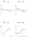
- the corrected value ( ⁇ ) is determined by correction functions shown in Figures 5a and 5b.
- the present invention is not limited to such examples as the correction functions shown in Figures 5a and 5b, and other application examples can exist.
- the brightness of enhanced signal (Y o ) is controlled by the corrected value depending on the correction functions shown in Figures 5a and 5b. That is, when the mean level (X m ) is very small, i.e., when an image is very dark, a corrected value ( ⁇ ) being larger than 0 is added to the mean level (X m ), and the mean-separate histogram equalization proposed by the present invention is then performed, whereby the mean brightness of the enhanced signal (Y o ) becomes high.
- the mean level (X m ) is very large, i.e., when an image is very bright, a corrected value ( ⁇ ) being smaller than 0 is added to the mean level (X m ), and the mean-separate histogram equalization proposed by the present invention is then performed, whereby the mean brightness of the enhanced signal (Y o ) becomes low. Accordingly, when the mean-separate histogram equalization is performed using the mean level (B m ) compensated by a predetermined appropriate corrected value ( ⁇ ) according to the mean level (X m ), the image quality of an input image can be remarkably enhanced.
- Figures 6a and 6b show the relationship between the mean level (X m ) and the compensated mean level (B m ) to which a corrected value (A) depending on the brightness correction function shown in Figures 5a and 5b is added.
- the first mapper 316 shown in Figure 4 receives the cumulative density function c L (X k ) calculated by the first CDF calculator 308, the signal (X k ) output from the first noise reducer 200, and the compensated mean level (B m ) output by the brightness compensator 314, and maps the samples ⁇ X ⁇ L of the first subimage to a gray level ranging from 0 to B m according to the cumulative density function.
- the second mapper 318 receives the cumulative density function c U (X k ) calculated by the second CDF calculator 310, the signal (X k ) output by the first noise reducer 200, and the compensated mean level (B m ) output by the brightness compensator 314, and maps the samples ⁇ X ⁇ U of the second subimage to a gray level ranging from B m ' to X L-1 according to the cumulative density function.
- B m ' B m + X L -1 /( L -1) wherein B m ' denotes a first gray level which is mapped in a higher region than the compensated mean level (B m ).
- the equation 18 shows the results of mapping input samples to (0,B m ) when they are equal to or smaller than the mean level (X m ) and mapping the input samples to (B m ',X L-1 ) when they are larger than the mean level (X m ).
- the equalized output (Y o ) becomes bright, and when it is smaller than 0 (i.e., ⁇ ⁇ 0), the equalized output (Y o ) becomes dark.
- ⁇ increases, a dynamic range at a lower region will be enhanced, and as the ⁇ decreases, a dynamic range at an upper region will be enhanced.
- a predetermined appropriate compensated mean level (B m ) depending on the mean level (X m ) greatly enhances the image quality of an input image.
- a comparator 320 compares the signal (X k ) output by the first noise reducer 200 with the mean level (X m ) output by the frame mean calculator 304 and generates a selection control signal.
- a first selector 322 selects the first mapper 316 when the signal (X k ) output by the first noise reducer 200 is lower than the mean level (X m ), and otherwise, selects the second mapper 318.
- the signal (X k ) input to the first and second mappers 316 and 318 is a signal of the frame next to a frame corresponding to the cumulative density function value output by the CDF memory 312.
- a frame memory for delaying a signal output by the first noise reducer 200 by one frame can be additionally provided to input a signal of the same frame as that of the cumulative density function output by the CDF memory 312 to the first and second mappers 316 and 318.
- the frame memory can be omitted using the characteristic that there is a high correlation between adjacent frames, so that hardware is reduced.
- the gray level distribution of an image signal of each subgroup by the CDF calculators 308 and 310 without the frame histogram calculator 302 is calculated, and a CDF can be calculated on the basis of the result.
- a subtracter 324 and an adder 334 perform a function of controlling the gain of the enhanced signal (Y o ).
- a basic concept of the gain control is that a variation of the maximum gray level of an input signal (Y) is restricted according to the degree of contrast enhancement when a contrast is enhanced using the mean-separate histogram equalization.
- the above equation 22 can be expressed by following equation 23 as the same equation. -r g(X k ) ⁇ ⁇ i ⁇ r ⁇ g(X k )
- the concept of restricting the amount of variation ⁇ k expressed as the equation 22 is related to the Weber's ratio.
- the following equation 24 can be obtained from the above equation 22.
- ⁇ k X k ⁇ wherein ⁇ k X k is the amount corresponding to the Weber's ratio.
- the Weber's ratio is an experimental fact that human beings feel that, when X 1 is changed by ⁇ X 1 and X 2 is changed by ⁇ X 2 , the degrees of the variations are the same.
- the concept of the gain control applied to the present invention is to control the gain, i.e., the enhancement degree of an enhanced signal using the mean-separate histogram having a brightness compensating function on the basis of the Weber's ratio.
- a gain feature determiner 326 restricts enhancement of the input signal (X k ) by outputting a maximum bounding function g(X k ) being a function of the input signal (X k ). For instance, when the g(X k ) is K1 and the K1 is a constant, the g(X k ) restricts input enhancement by identical amount regardless of an input gray level value.
- the maximum bounding function g(X k ) can be equal to aX k or a X k (here, a is a constant), and differently restricts the enhanced amount of an input image according to the input gray level value.
- a second selector 328 compares the input signal (X k ) with the mean level (X m ) output by the frame mean calculator 304, and selects a first gain control parameter ( ⁇ L ) when the input signal (X k ) is lower than or equal to the mean level (X m ) and otherwise, selects a second gain control parameter ( ⁇ U ).
- the first gain control parameter ( ⁇ L ) is a parameter for a first subimage signal
- the second gain control parameter ( ⁇ U ) is a parameter for a second subimage signal.
- the first and second gain control parameters ( ⁇ L ) and ( ⁇ U ) can be given as the same value to the input signal in contrast that different gain control parameters are provided to each subimage.
- a multiplier 330 multiplies the value of the maximum bounding function g(X k ) output by the gain feature determiner 326 by a gain control parameter ( ⁇ ) selected by the second selector 328 and outputs a limit value ( ⁇ ⁇ g(X k )).
- the limit value ⁇ ⁇ g(X k ) is a characteristic of the gain control according to the present invention.
- a limiter 332 compares the variation amount ( ⁇ k ) output by the subtracter 324 with the limit value ⁇ ⁇ g(X k ) output by the multiplier 330, restricts the variation amount ( ⁇ k ), and outputs a restricted variation amount ( ⁇ k ') like the following equation 25.
- the variation amount ( ⁇ k ) is used as the restricted variation amount ( ⁇ k ').
- the variation amount ( ⁇ k ) is greater than ⁇ ⁇ g(X k )
- the variation amount ( ⁇ k ) is restricted to the ⁇ ⁇ g(X k ).
- the variation amount ( ⁇ k ) is smaller than - ⁇ ⁇ g(X k )
- the variation amount ( ⁇ k ) is restricted to the - ⁇ ⁇ g(X k ), thereby controlling the gain of the enhanced signal (Y o ).
- the adder 334 adds the input signal (X k ) to the restricted variation amount ( ⁇ k ') output by the limiter 332 and outputs an output signal (Y H ) as shown in the following equation 26.
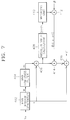
- FIG 7 is a detailed block diagram of the local contrast enhancer 400 shown in Figure 1, wherein an M ⁇ N window generator 402 receiving the output (Y H ) of the contrast enhancer 300 shown in Figure 1 generates an M ⁇ N window (W) which can be expressed by the following equation 27, and outputs it to an M ⁇ N low-pass filter (LPF) 404.
- M ⁇ N window generator 402 receiving the output (Y H ) of the contrast enhancer 300 shown in Figure 1 generates an M ⁇ N window (W) which can be expressed by the following equation 27, and outputs it to an M ⁇ N low-pass filter (LPF) 404.
- M ⁇ N window generator 402 receiving the output (Y H ) of the contrast enhancer 300 shown in Figure 1 generates an M ⁇ N window (W) which can be expressed by the following equation 27, and outputs it to an M ⁇ N low-pass filter (LPF) 404.
- LPF low-pass filter
- a middle sample (x) of a center line of the M ⁇ N window (W) is input to a subtracter 406 and an adder 416.
- the middle sample (x) of the center line is an input sample for improving a contrast.
- FIG 8 is a detailed circuit diagram of the M ⁇ N window generator 402 when both M and N are equal to 3.
- D and H denote a sample delay and a line memory, respectively.
- the output signal (m) of the M ⁇ N LPF 404 shown in Figure 7 can be represented by the following equation 28. wherein b ij is a predetermined coefficient, and corresponds to an impulse response of the M ⁇ NLPF 404.
- a subtracter 406 subtracts the output signal (m) of the M ⁇ N LPF 404 from the middle sample value (x).
- An absolute value calculator 408 calculates an absolute value of the output of the subtracter 406, and a weighting unit 410 outputs a value obtained by weighting the output of the absolute value calculator 408 using a predetermined weighting function f(
- a first multiplier 412 multiplies a predetermined parameter ( ⁇ ) by the output of the weighting unit 410.
- a second multiplier 414 multiplies the output of the subtracter 406 by the output of the first multiplier 412 and outputs the multiplied result ⁇ f(
- An adder 416 adds the multiplied result to the middle sample (x) of the M ⁇ N window generator 402.
- a difference between the middle sample (x) of the M ⁇ Nwindow generator 402 and the output signal (m) of the M ⁇ N LPF 404 can be defined as a contrast visually felt by a human being, i.e., a local contrast.
- is large can be called a region having a high contrast
- is small can be called a region having a low contrast.
- the local contrast is enhanced by amplifying the value
- the output (Y') of the adder 416 will be expressed by following equation 29.
- Y' x + ⁇ f(
- f() being a weighting function
- ⁇ is a parameter for adjusting the amount of enhancement of an entire local contrast.
- Figure 9 show examples of a weighting function for determining a weighted value of a local contrast according to
- Various contrast enhancement characteristics can be obtained by using the weighting functions indicated by (a) and (b).
- a colour signal C is given as R, G and B signals
- the luminance signal Y shown in the equation 1 is given as a1R+a2G+a3B
- Y is converted into Y' through the contrast enhancer 300 and the local contrast enhancer 400.
- the basic concept of the colour compensation according to the present invention is to change a given colour to the colour direction in a (R,G,B) space.
- the compensated colour C' on the Y' plane is obtained by detecting an intersecting point of the straight line OC and the Y' plane.
- the original colour signal C shown in Figure 10 is mapped into the new colour signal C' when the luminance value is changed from Y to Y', which is the intersecting point of the straight line OC and the Y' plane.
- Equations 34 through 36 can be also expressed as following Equations 41 through 53 by using the result of the Equation 40.
- C' (R' ,G' ,B')
- C' (qR,qG,qB) wherein q equals Y'/Y which is a ratio between the original luminance signal and the resultant luminance signal. Since this means that the ratio of a luminance change is equal to that of a colour change, the present invention performs colour compensation by changing a colour value according to the luminance change.
- Equation 45 The colour compensation can be easily performed on other colour systems using the result of Equation 45. That is, for instance, the (Y,U,V) signals given in Equation 1, being the results of the colour compensation given in Equation 45, should be converted into (qY,qU,qV) as shown in following Equations 46 to 51:
- U' b 1 R' + b 2 G' + b 3 B'
- U q(b 1 R + b 2 G + b 3 B)
- U qU and
- V' c 1 R' + c 2 G' + c 3 B'
- V q(c 1 R + c 2 G + c 3 B)
- V qV
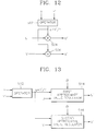
- FIG 12 is a detailed circuit diagram of the colour compensator 500 shown in Figure 1 according to an embodiment of the present invention, wherein an operator 502 operates a ratio (q) between a signal Y output by the first noise reducer 200 of Figure 1 and a signal Y' output by the local contrast enhancer 400, i.e., the Y'/Y.
- q a ratio between a signal Y output by the first noise reducer 200 of Figure 1 and a signal Y' output by the local contrast enhancer 400, i.e., the Y'/Y.
- a first multiplier 504 multiplies a signal U output by the second noise reducer 220 of Figure 1 by the ratio (q) output by the operator 502 and outputs a signal U'.
- a second multiplier 506 multiplies a signal V output by the third noise reducer 240 of Figure 1 by the ratio (q) output by the operator 502 and outputs a signal V'.
- FIG 13 is a detailed circuit diagram of the colour compensator 500 shown in Figure 1 according to another embodiment of the present invention, wherein an operator 512 operates a ratio (q) between a signal Y output by the first noise reducer 200 of Figure 1 and a signal Y' output by the local contrast enhancer 400, i.e., the Y'/Y.
- First approximate value regulators 514 and 516 are provided to prevent colour compensation using the approximated compensating line shown in Figure 11.
- embodiments of the present invention are applicable to a wide-ranging field associated with image quality enhancement for an image signal. That is, the present invention can be applied to broadcasting apparatuses, radar signal processing systems, medical equipment, electric home appliances, etc.
- embodiments of the present invention which considers a corrected value depending on the mean brightness of an input image and uses the mean-separate histogram equalization having the gain control function for preventing excessive enhancement, effectively reduce an abrupt change in brightness and an artifact generated during conventional histogram equalization, thereby enhancing a contrast and greatly improving the image quality of an input image. Furthermore, embodiments of the present invention effectively remove impulse noise by increasing reliability through a dual impulse detecting method, thus improving the image quality. The image quality can also be enhanced through enhancement of a local contrast. Also, when a luminance is changed by a predetermined process for contrast enhancement, embodiments of the present invention vary a colour value according to the change, thereby providing an undistorted colour signal.
Landscapes
- Engineering & Computer Science (AREA)
- Multimedia (AREA)
- Signal Processing (AREA)
- Picture Signal Circuits (AREA)
- Image Processing (AREA)
- Transforming Electric Information Into Light Information (AREA)
- Processing Of Color Television Signals (AREA)
Applications Claiming Priority (2)
| Application Number | Priority Date | Filing Date | Title |
|---|---|---|---|
| KR1019960043133A KR100200628B1 (ko) | 1996-09-30 | 1996-09-30 | 화질 개선 회로 및 그 방법 |
| KR9643133 | 1996-09-30 |
Publications (2)
| Publication Number | Publication Date |
|---|---|
| EP0833501A2 true EP0833501A2 (fr) | 1998-04-01 |
| EP0833501A3 EP0833501A3 (fr) | 1999-12-01 |
Family
ID=19475717
Family Applications (1)
| Application Number | Title | Priority Date | Filing Date |
|---|---|---|---|
| EP97307183A Withdrawn EP0833501A3 (fr) | 1996-09-30 | 1997-09-16 | Circuit et procédé d'amélioration de la qualité d'image |
Country Status (5)
| Country | Link |
|---|---|
| US (1) | US6078686A (fr) |
| EP (1) | EP0833501A3 (fr) |
| JP (1) | JP3187348B2 (fr) |
| KR (1) | KR100200628B1 (fr) |
| CN (1) | CN1149828C (fr) |
Cited By (13)
| Publication number | Priority date | Publication date | Assignee | Title |
|---|---|---|---|---|
| EP1017241A2 (fr) * | 1998-12-31 | 2000-07-05 | Eastman Kodak Company | Methode de compensation de couleur d'image lors de l'ajustement du contraste d'une image couleur numérique |
| EP1017229A2 (fr) * | 1998-12-31 | 2000-07-05 | Eastman Kodak Company | Procédé de préservation de détails spatiaux et des informations de couleur pendant le réglage d'échelle de tonalité d'une image en couleur numérique |
| EP1075140A1 (fr) * | 1999-08-02 | 2001-02-07 | Koninklijke Philips Electronics N.V. | Amélioration d'un signal vidéo |
| WO2001015434A1 (fr) * | 1999-08-25 | 2001-03-01 | Intel Corporation | Procede et appareil permettant une mise au point automatique dans un systeme de capture d'images utilisant des filtres symetriques fir |
| EP1109130A2 (fr) * | 1999-12-15 | 2001-06-20 | Eastman Kodak Company | Procédé et appareil pour le traitement d'images avec réduction du bruit et réglage d'échelle de tonalité |
| WO2001059183A2 (fr) | 2000-02-14 | 2001-08-16 | Koninklijke Philips Electronics N.V. | Mise en valeur d'un signal d'image |
| EP1486915A1 (fr) * | 2003-06-11 | 2004-12-15 | Agfa-Gevaert | Procédé et interface utilisateur pour modifier au moins le contraste ou la densité des pixels d'une image traitée |
| WO2006081277A1 (fr) * | 2005-01-27 | 2006-08-03 | Qualcomm Incorporated | Adaptation de luminance pour le traitement d'images numeriques |
| EP1786214A2 (fr) * | 2005-11-14 | 2007-05-16 | Pioneer Corporation | Dispositif d'affichage, circuit de traitement de signaux, programme et procédé d'affichage |
| EP1919188A3 (fr) * | 2006-10-30 | 2010-10-06 | Sony Corporation | Appareil de traitement d'images, appareil de capture d'images, procédé de traitement d'images dans ces appareils, et programme permettant à un ordinateur d'exécuter le procédé |
| CN101742338B (zh) * | 2008-11-05 | 2012-10-24 | 美格纳半导体有限会社 | 锐度增强设备及方法 |
| US8305427B2 (en) | 2005-03-22 | 2012-11-06 | Olympus Corporation | Image processor and endoscope apparatus |
| US8487958B2 (en) | 2008-11-27 | 2013-07-16 | Agfa Healthcare N.V. | Method and system for changing image density and contrast |
Families Citing this family (71)
| Publication number | Priority date | Publication date | Assignee | Title |
|---|---|---|---|---|
| US6018588A (en) * | 1996-10-09 | 2000-01-25 | Samsung Electronics Co., Ltd. | Image enhancement circuit and method using mean matching/quantized mean matching histogram equalization and color compensation |
| JP3668014B2 (ja) * | 1998-03-09 | 2005-07-06 | 富士写真フイルム株式会社 | 画像処理方法及び装置 |
| WO2000046983A1 (fr) * | 1999-02-05 | 2000-08-10 | Koninklijke Philips Electronics N.V. | Egalisation d'histogramme |
| JP3878351B2 (ja) * | 1999-02-23 | 2007-02-07 | 富士フイルムホールディングス株式会社 | 色変換装置および方法 |
| US6640017B1 (en) | 1999-05-26 | 2003-10-28 | Intel Corporation | Method and apparatus for adaptively sharpening an image |
| US6697534B1 (en) * | 1999-06-09 | 2004-02-24 | Intel Corporation | Method and apparatus for adaptively sharpening local image content of an image |
| US6721000B1 (en) * | 2000-02-23 | 2004-04-13 | Neomagic Corp. | Adaptive pixel-level color enhancement for a digital camera |
| TW508940B (en) * | 2000-03-28 | 2002-11-01 | Omnivision Tech Inc | Method and apparatus for color image date processing and compression |
| WO2005020130A2 (fr) * | 2000-08-18 | 2005-03-03 | Paul Reed Smith Guitars, Limited Partnership | Procede d'accentuation de couleurs avec compensation et ajustement |
| JP4666274B2 (ja) * | 2001-02-20 | 2011-04-06 | 日本電気株式会社 | カラー画像処理装置及びその方法 |
| US20020172431A1 (en) * | 2001-03-07 | 2002-11-21 | Atkins C. Brian | Digital image appearance enhancement and compressibility improvement method and system |
| TW524011B (en) * | 2001-08-10 | 2003-03-11 | Veutron Corp | Circuit using RGB signals of scanner for color space conversion |
| KR100393071B1 (ko) * | 2001-08-18 | 2003-07-31 | 삼성전자주식회사 | 영상의 히스토그램 평활화 장치 및 방법 |
| CA2365893A1 (fr) * | 2001-12-21 | 2003-06-21 | Jaldi Semiconductor Corp. | Systeme et methode permettant de rehausser la qualite dynamique de l'espace chromatique |
| US6873657B2 (en) * | 2001-12-27 | 2005-03-29 | Koninklijke Philips Electronics, N.V. | Method of and system for improving temporal consistency in sharpness enhancement for a video signal |
| US6862372B2 (en) * | 2001-12-27 | 2005-03-01 | Koninklijke Philips Electronics N.V. | System for and method of sharpness enhancement using coding information and local spatial features |
| KR100466785B1 (ko) * | 2002-01-18 | 2005-01-17 | (주)플렛디스 | 평판 디스플레이 패널의 화질 제어장치 및 방법 |
| EP1337104B1 (fr) * | 2002-02-19 | 2014-01-08 | FUJIFILM Corporation | Appareil, procédé et programme de traitement d'image |
| CN100450190C (zh) * | 2002-07-17 | 2009-01-07 | 皇家飞利浦电子股份有限公司 | 非线性图像处理的方法和实现该方法的设备 |
| US20050213125A1 (en) * | 2002-08-19 | 2005-09-29 | Paul Reed Smith Guitars, Limited Partnership | Method of color accentuation with compensation and adjustment |
| KR100871686B1 (ko) * | 2002-08-23 | 2008-12-05 | 삼성전자주식회사 | 색상보존을 위한 대비 및 명도 개선방법 및 장치 |
| US7164808B2 (en) * | 2002-08-27 | 2007-01-16 | Hrl Laboratories, Llc | Method and apparatus for illumination compensation of digital images |
| US7321699B2 (en) * | 2002-09-06 | 2008-01-22 | Rytec Corporation | Signal intensity range transformation apparatus and method |
| US7477781B1 (en) * | 2002-10-10 | 2009-01-13 | Dalsa Corporation | Method and apparatus for adaptive pixel correction of multi-color matrix |
| WO2004068411A1 (fr) * | 2003-01-31 | 2004-08-12 | Fujitsu Limited | Dispositif de filtrage de valeur moyenne et procede de filtrage |
| GB2398379A (en) * | 2003-02-11 | 2004-08-18 | Qinetiq Ltd | Automated digital image analysis |
| US7483083B2 (en) * | 2003-04-16 | 2009-01-27 | Intervideo, Inc. | Movie enhancement |
| KR100513273B1 (ko) * | 2003-07-04 | 2005-09-09 | 이디텍 주식회사 | 동영상 신호의 실시간 밝기 제어 장치 및 방법 |
| KR20050008391A (ko) * | 2003-07-15 | 2005-01-21 | 삼성전자주식회사 | 화질개선장치 및 그 방법 |
| JP4077430B2 (ja) * | 2003-07-31 | 2008-04-16 | 佳知 高石 | 骨密度評価装置および骨密度評価方法 |
| KR101138852B1 (ko) * | 2003-11-04 | 2012-05-14 | 코닌클리케 필립스 일렉트로닉스 엔.브이. | 모바일 디스플레이를 위한 스마트 클리퍼 |
| US7110046B2 (en) * | 2003-11-04 | 2006-09-19 | Cyberlink Corp. | Method for dynamically adjusting video brightness |
| US7362361B2 (en) * | 2003-11-28 | 2008-04-22 | Victor Compay Of Japan, Ltd. | Noise suppressing circuit using luminance detection |
| US7515748B2 (en) * | 2004-01-22 | 2009-04-07 | Lexmark International, Inc. | Controlled moving window adaptive histogram equalization |
| US7532755B2 (en) * | 2004-01-22 | 2009-05-12 | Lexmark International, Inc. | Image classification using concentration ratio |
| US7545421B2 (en) * | 2004-10-28 | 2009-06-09 | Qualcomm Incorporated | Apparatus, system, and method for optimizing gamma curves for digital image devices |
| US7590303B2 (en) * | 2005-09-29 | 2009-09-15 | Samsung Electronics Co., Ltd. | Image enhancement method using local illumination correction |
| KR101128454B1 (ko) * | 2005-11-10 | 2012-03-23 | 삼성전자주식회사 | 콘트라스트 향상 방법 및 장치 |
| KR100726351B1 (ko) * | 2005-11-30 | 2007-06-13 | 중앙대학교 산학협력단 | 이미지/노이즈 판별을 위한 통계적 영상처리 시스템 및방법 |
| US8295596B1 (en) * | 2005-12-07 | 2012-10-23 | Marvell International Ltd. | Adaptive histogram-based video contrast enhancement |
| US7746411B1 (en) * | 2005-12-07 | 2010-06-29 | Marvell International Ltd. | Color management unit |
| KR101225058B1 (ko) * | 2006-02-14 | 2013-01-23 | 삼성전자주식회사 | 콘트라스트 조절 방법 및 장치 |
| KR101208680B1 (ko) * | 2006-03-22 | 2012-12-10 | 삼성전자주식회사 | 영상디스플레이장치 및 컬러왜곡 보상방법 |
| KR100843084B1 (ko) * | 2006-06-22 | 2008-07-02 | 삼성전자주식회사 | 노이즈 저감 방법 및 장치 |
| KR100846907B1 (ko) * | 2006-06-24 | 2008-07-17 | 엘지전자 주식회사 | 영상표시기기의 화질 조정장치 및 방법 |
| KR101303665B1 (ko) * | 2007-06-13 | 2013-09-09 | 삼성전자주식회사 | 콘트라스트 향상 방법 및 장치 |
| CN101742086B (zh) * | 2008-11-07 | 2013-05-15 | 联咏科技股份有限公司 | 影像噪声消除方法 |
| EP2404281A1 (fr) * | 2009-03-06 | 2012-01-11 | Koninklijke Philips Electronics N.V. | Procédé pour convertir des données d'image d'entrée en données d'image de sortie, unité de conversion d'image pour convertir des données d'image d'entrée en données d'image de sortie, appareil de traitement d'image, dispositif d'affichage |
| JP5529424B2 (ja) * | 2009-03-11 | 2014-06-25 | ソニー株式会社 | 画像処理装置、画像処理方法及びコンピュータプログラム |
| JP2010220030A (ja) * | 2009-03-18 | 2010-09-30 | Mitsubishi Electric Corp | 映像補正回路および映像表示装置 |
| US8537177B2 (en) | 2009-06-15 | 2013-09-17 | Marvell World Trade Ltd. | System and methods for gamut bounded saturation adaptive color enhancement |
| TWI408619B (zh) * | 2009-11-16 | 2013-09-11 | Inst Information Industry | 影像對比提昇裝置及其方法 |
| KR101113483B1 (ko) * | 2010-04-09 | 2012-03-06 | 동아대학교 산학협력단 | 컬러 영상의 가시성 향상 장치 및 방법 |
| EP2601636A1 (fr) | 2010-08-05 | 2013-06-12 | Ramot at Tel Aviv University, Ltd. | Procédé et système de traitement d'une image représentant plusieurs échelles |
| CN103460682B (zh) * | 2011-03-24 | 2016-08-17 | 三菱电机株式会社 | 图像处理装置和方法 |
| US8463037B2 (en) * | 2011-03-31 | 2013-06-11 | Sony Corporation | Detection of low contrast for image processing |
| KR101906422B1 (ko) * | 2012-05-10 | 2018-10-10 | 엘지디스플레이 주식회사 | 화질처리방법과 이를 이용한 표시장치 |
| JP5178933B1 (ja) * | 2012-05-21 | 2013-04-10 | 正浩 小林 | 画像処理装置 |
| JP5202749B1 (ja) * | 2012-09-03 | 2013-06-05 | 正浩 小林 | 画像処理方法 |
| US9324137B2 (en) * | 2012-10-24 | 2016-04-26 | Marvell World Trade Ltd. | Low-frequency compression of high dynamic range images |
| KR20140102521A (ko) * | 2013-02-14 | 2014-08-22 | 삼성전자주식회사 | 내시경 장치 및 그 제어 방법 |
| US20140267679A1 (en) * | 2013-03-13 | 2014-09-18 | Leco Corporation | Indentation hardness test system having an autolearning shading corrector |
| KR20140122605A (ko) * | 2013-04-10 | 2014-10-20 | 삼성전자주식회사 | 입력 영상의 밝기 조절 장치 및 방법 |
| TWI485694B (zh) * | 2013-05-09 | 2015-05-21 | Asustek Comp Inc | 影像色彩調整方法與其電子裝置 |
| US20150146981A1 (en) * | 2013-09-05 | 2015-05-28 | Tp Vision Holding B.V. | Apparatus and method for converting input image data into output image data, image conversion unit for converting input image data into output image data, image processing apparatus, display device |
| KR102251440B1 (ko) | 2014-11-05 | 2021-05-14 | 삼성전자주식회사 | 로컬 톤 맵핑 회로와 이를 포함하는 모바일 컴퓨팅 장치 |
| CN106409254B (zh) * | 2016-10-08 | 2019-09-24 | 武汉华星光电技术有限公司 | 一种rgb转rgbw的色域转换方法及装置 |
| KR102522355B1 (ko) * | 2017-02-13 | 2023-04-17 | 고려대학교 산학협력단 | 영상의 대조비 개선 장치 및 방법 |
| KR102575126B1 (ko) * | 2018-12-26 | 2023-09-05 | 주식회사 엘엑스세미콘 | 영상 처리 장치 및 그 방법 |
| CN111131716B (zh) * | 2019-12-31 | 2021-06-15 | 联想(北京)有限公司 | 图像处理方法以及电子设备 |
| CN117934353A (zh) * | 2024-03-20 | 2024-04-26 | 上海玄戒技术有限公司 | 一种图像处理方法、装置、设备、存储介质及芯片 |
Citations (4)
| Publication number | Priority date | Publication date | Assignee | Title |
|---|---|---|---|---|
| US4794531A (en) * | 1984-11-07 | 1988-12-27 | Hitachi, Ltd | Unsharp masking for image enhancement |
| EP0457537A2 (fr) * | 1990-05-14 | 1991-11-21 | Kabushiki Kaisha Toshiba | Appareil pour le traitement d'images en couleurs |
| WO1996014708A1 (fr) * | 1994-11-04 | 1996-05-17 | Motorola Inc. | Procede, filtre de post-traitement et systeme de compression video pour eliminer les artefacts de type moustiques et de blocs |
| EP0747855A2 (fr) * | 1995-06-05 | 1996-12-11 | Xerox Corporation | Appareil et procédé d'amélioration des images numériques |
Family Cites Families (7)
| Publication number | Priority date | Publication date | Assignee | Title |
|---|---|---|---|---|
| DE3629396C2 (de) * | 1986-08-29 | 1993-12-23 | Agfa Gevaert Ag | Verfahren zur elektronischen Bildverarbeitung |
| DE3629409C2 (de) * | 1986-08-29 | 1994-02-17 | Agfa Gevaert Ag | Verfahren und Vorrichtung zur Kontrastbewertung bei der elektronischen Bildverarbeitung |
| US4991092A (en) * | 1988-08-12 | 1991-02-05 | The Regents Of The University Of California | Image processor for enhancing contrast between subregions of a region of interest |
| KR100207660B1 (ko) * | 1996-03-09 | 1999-07-15 | 윤종용 | 양자화된 평균 분리 히스토그램 등화를 이용한 화질 개선 방법 및 그 회로 |
| JP3130266B2 (ja) * | 1996-03-09 | 2001-01-31 | 三星電子株式会社 | 平均分離ヒストグラム等化を用いる映像改善方法及びその回路 |
| DE69716803T2 (de) * | 1996-04-10 | 2003-03-27 | Samsung Electronics Co Ltd | Bildqualitätverbesserungsverfahren durch Histogramm-Entzerrung mit Mittelwertübereinstimmung und Schaltung dafür |
| JP3280888B2 (ja) * | 1996-08-19 | 2002-05-13 | 三星電子株式会社 | 量子化された平均−マッチングヒストグラム等化を用いた画質改善方法及びその回路 |
-
1996
- 1996-09-30 KR KR1019960043133A patent/KR100200628B1/ko not_active IP Right Cessation
-
1997
- 1997-09-05 JP JP24119597A patent/JP3187348B2/ja not_active Expired - Fee Related
- 1997-09-16 EP EP97307183A patent/EP0833501A3/fr not_active Withdrawn
- 1997-09-30 CN CNB971200173A patent/CN1149828C/zh not_active Expired - Fee Related
- 1997-09-30 US US08/941,669 patent/US6078686A/en not_active Expired - Fee Related
Patent Citations (4)
| Publication number | Priority date | Publication date | Assignee | Title |
|---|---|---|---|---|
| US4794531A (en) * | 1984-11-07 | 1988-12-27 | Hitachi, Ltd | Unsharp masking for image enhancement |
| EP0457537A2 (fr) * | 1990-05-14 | 1991-11-21 | Kabushiki Kaisha Toshiba | Appareil pour le traitement d'images en couleurs |
| WO1996014708A1 (fr) * | 1994-11-04 | 1996-05-17 | Motorola Inc. | Procede, filtre de post-traitement et systeme de compression video pour eliminer les artefacts de type moustiques et de blocs |
| EP0747855A2 (fr) * | 1995-06-05 | 1996-12-11 | Xerox Corporation | Appareil et procédé d'amélioration des images numériques |
Cited By (25)
| Publication number | Priority date | Publication date | Assignee | Title |
|---|---|---|---|---|
| EP1017229A3 (fr) * | 1998-12-31 | 2002-10-09 | Eastman Kodak Company | Procédé de préservation de détails spatiaux et des informations de couleur pendant le réglage d'échelle de tonalité d'une image en couleur numérique |
| EP1017229A2 (fr) * | 1998-12-31 | 2000-07-05 | Eastman Kodak Company | Procédé de préservation de détails spatiaux et des informations de couleur pendant le réglage d'échelle de tonalité d'une image en couleur numérique |
| EP1017241A2 (fr) * | 1998-12-31 | 2000-07-05 | Eastman Kodak Company | Methode de compensation de couleur d'image lors de l'ajustement du contraste d'une image couleur numérique |
| EP1017241A3 (fr) * | 1998-12-31 | 2004-01-21 | Eastman Kodak Company | Methode de compensation de couleur d'image lors de l'ajustement du contraste d'une image couleur numérique |
| EP1075140A1 (fr) * | 1999-08-02 | 2001-02-07 | Koninklijke Philips Electronics N.V. | Amélioration d'un signal vidéo |
| WO2001010116A1 (fr) * | 1999-08-02 | 2001-02-08 | Koninklijke Philips Electronics N.V. | Mise en valeur d'un signal video |
| WO2001015434A1 (fr) * | 1999-08-25 | 2001-03-01 | Intel Corporation | Procede et appareil permettant une mise au point automatique dans un systeme de capture d'images utilisant des filtres symetriques fir |
| US6373481B1 (en) | 1999-08-25 | 2002-04-16 | Intel Corporation | Method and apparatus for automatic focusing in an image capture system using symmetric FIR filters |
| GB2370111A (en) * | 1999-08-25 | 2002-06-19 | Intel Corp | Method and apparatus for automatic focusing in an image capture ystem using symmetric fir filters |
| AU771694B2 (en) * | 1999-08-25 | 2004-04-01 | Intel Corporation | Method and apparatus for automatic focusing in an image capture ystem using symmetric FIR filters |
| GB2370111B (en) * | 1999-08-25 | 2003-12-31 | Intel Corp | Method and apparatus for automatic focusing in an image capture ystem using symmetric fir filters |
| EP1109130A2 (fr) * | 1999-12-15 | 2001-06-20 | Eastman Kodak Company | Procédé et appareil pour le traitement d'images avec réduction du bruit et réglage d'échelle de tonalité |
| EP1109130A3 (fr) * | 1999-12-15 | 2003-09-10 | Eastman Kodak Company | Procédé et appareil pour le traitement d'images avec réduction du bruit et réglage d'échelle de tonalité |
| WO2001059183A2 (fr) | 2000-02-14 | 2001-08-16 | Koninklijke Philips Electronics N.V. | Mise en valeur d'un signal d'image |
| US7619691B2 (en) | 2000-02-14 | 2009-11-17 | Koninklijke Philips Electronics N. V. | Picture signal enhancement |
| EP1486915A1 (fr) * | 2003-06-11 | 2004-12-15 | Agfa-Gevaert | Procédé et interface utilisateur pour modifier au moins le contraste ou la densité des pixels d'une image traitée |
| WO2006081277A1 (fr) * | 2005-01-27 | 2006-08-03 | Qualcomm Incorporated | Adaptation de luminance pour le traitement d'images numeriques |
| US7986351B2 (en) | 2005-01-27 | 2011-07-26 | Qualcomm Incorporated | Luma adaptation for digital image processing |
| US8305427B2 (en) | 2005-03-22 | 2012-11-06 | Olympus Corporation | Image processor and endoscope apparatus |
| EP1786214A2 (fr) * | 2005-11-14 | 2007-05-16 | Pioneer Corporation | Dispositif d'affichage, circuit de traitement de signaux, programme et procédé d'affichage |
| EP1786214A3 (fr) * | 2005-11-14 | 2008-11-05 | Pioneer Corporation | Dispositif d'affichage, circuit de traitement de signaux, programme et procédé d'affichage |
| EP1919188A3 (fr) * | 2006-10-30 | 2010-10-06 | Sony Corporation | Appareil de traitement d'images, appareil de capture d'images, procédé de traitement d'images dans ces appareils, et programme permettant à un ordinateur d'exécuter le procédé |
| US8036457B2 (en) | 2006-10-30 | 2011-10-11 | Sony Corporation | Image processing apparatus with noise reduction capabilities and a method for removing noise from a captured image |
| CN101742338B (zh) * | 2008-11-05 | 2012-10-24 | 美格纳半导体有限会社 | 锐度增强设备及方法 |
| US8487958B2 (en) | 2008-11-27 | 2013-07-16 | Agfa Healthcare N.V. | Method and system for changing image density and contrast |
Also Published As
| Publication number | Publication date |
|---|---|
| CN1149828C (zh) | 2004-05-12 |
| JP3187348B2 (ja) | 2001-07-11 |
| EP0833501A3 (fr) | 1999-12-01 |
| US6078686A (en) | 2000-06-20 |
| CN1183696A (zh) | 1998-06-03 |
| KR19980023635A (ko) | 1998-07-06 |
| JPH10136231A (ja) | 1998-05-22 |
| KR100200628B1 (ko) | 1999-06-15 |
Similar Documents
| Publication | Publication Date | Title |
|---|---|---|
| EP0833501A2 (fr) | Circuit et procédé d'amélioration de la qualité d'image | |
| JP3130266B2 (ja) | 平均分離ヒストグラム等化を用いる映像改善方法及びその回路 | |
| US6049626A (en) | Image enhancing method and circuit using mean separate/quantized mean separate histogram equalization and color compensation | |
| US6040860A (en) | Imaging apparatus for supplying images with rich gradation across the entire luminance range for all subject types | |
| US5808697A (en) | Video contrast enhancer | |
| KR100207660B1 (ko) | 양자화된 평균 분리 히스토그램 등화를 이용한 화질 개선 방법 및 그 회로 | |
| EP0592196B1 (fr) | Circuits d'élimination du bruit | |
| US5166788A (en) | Motion signal processor | |
| EP1326425A2 (fr) | Appareil et procéde de regulation de la saturation d'images en couleurs | |
| US20120170843A1 (en) | Methods for performing local tone mapping | |
| US20070041636A1 (en) | Apparatus and method for image contrast enhancement using RGB value | |
| US7292734B2 (en) | Black and white stretching system and method for improving contrast of a picture | |
| EP2073170A1 (fr) | Appareil de traitement d'image et procédé de correction de contraste | |
| JPH0723287A (ja) | 撮像装置 | |
| KR20160001582A (ko) | 화상 처리 장치 및 화상 처리 방법 | |
| KR100213109B1 (ko) | 잡음 감소와 히스토그램 등화를 이용한 화질 개선회로 및 그 방법 | |
| KR100188679B1 (ko) | 밝기보상기능을 가진 평균 분리 히스토그램 등화를이용한화질개선방법과그회로 | |
| KR100200630B1 (ko) | 밝기 보상 기능을 가진 양자화된 평균-매칭 히스토그램 등화를 이용한 화질 개선방법 및 그 회로 | |
| KR100200611B1 (ko) | 이득 조절 기능을 가진 평균-분리 히스토그램 등화를 이용한 화질 개선 방법 및 그 회로 | |
| KR100200631B1 (ko) | 평균 분리 히스토그램 등화와 칼라 보상을 이용한 칼라 신호의 화질 개선방법 및그 회로 | |
| KR100230261B1 (ko) | 양자화된 평균 분리 히스토그램 등화와 칼라 보상을 이용한 칼라신호의 화질 개선방법 및 그 회로 | |
| KR100195123B1 (ko) | 저역 필터링된 신호의 평균-매칭 히스토그램 등화를 이용한 화질 개선방법 및 그 회로 | |
| KR19980015067A (ko) | 밝기 보상 기능을 가진 양자화된 평균-분리 히스토그램 등화를 이용한 화질 개선 방법 및 그 회로 | |
| KR100195116B1 (ko) | 이득 조절 기능을 가진 평균-매칭 히스토그램 등화를 이용한 화질 개선방법 및 그 회로 | |
| KR100219612B1 (ko) | 양자화된 평균 매칭 히스토그램 등화와 칼라 보상을 이용한 칼라 신호의 화질 개선방법 및 그 회로 |
Legal Events
| Date | Code | Title | Description |
|---|---|---|---|
| PUAI | Public reference made under article 153(3) epc to a published international application that has entered the european phase |
Free format text: ORIGINAL CODE: 0009012 |
|
| 17P | Request for examination filed |
Effective date: 19970923 |
|
| AK | Designated contracting states |
Kind code of ref document: A2 Designated state(s): DE ES GB |
|
| PUAL | Search report despatched |
Free format text: ORIGINAL CODE: 0009013 |
|
| AK | Designated contracting states |
Kind code of ref document: A3 Designated state(s): AT BE CH DE DK ES FI FR GB GR IE IT LI LU MC NL PT SE |
|
| RIC1 | Information provided on ipc code assigned before grant |
Free format text: 6H 04N 1/58 A, 6G 06T 5/20 B |
|
| AKX | Designation fees paid |
Free format text: DE ES GB |
|
| STAA | Information on the status of an ep patent application or granted ep patent |
Free format text: STATUS: THE APPLICATION HAS BEEN WITHDRAWN |
|
| 18W | Application withdrawn |
Effective date: 20040716 |