The present invention relates to image quality
enhancement, and more particularly, to an image quality
enhancing circuit having functions such as noise
reduction, contrast enhancement based on histogram
equalization, local contrast enhancement and colour
compensation and a method therefor.
In general, the image quality of a video signal can
be deteriorated due to various factors. A low contrast
can be a factor among representative ones of image quality
degradation. As a method for correcting the image quality
degradation, there are gamma correction for making a
correction according to a variation in brightness,
histogram equalization, etc.
The principal operation of the histogram equalization
is to convert a given input image on the basis of the
histogram of the input image. Here, the histogram
represents gray level distribution at a given input image.
Such a histogram of the gray level provides an entire
depiction on the appearance of an image. A gray level
appropriately adjusted according to sample distribution of
an image enhances the appearance and contrast of the
image.
The histogram equalization for enhancing the contrast
of a given image according to sample distribution of the
image is the most widely known among various contrast
enhancing methods, which is disclosed in the following
documents: [1] J.S.Lim, "Two-Dimensional Signal and Image
Processing," Prentice Hall, Englewood Cliffs, New Jersey,
1990; and [2] R.C.Gonzalez and P.Wints, "Digital Image
Processing," Addison-Wesley, Reading, Massachusetts, 1977.
Also, useful applications of the histogram
equalization including medical image processing and radar
image processing are disclosed in the following documents:
[3] J.Zimmerman, S.Pizer, E.Staab, E.Perry, W.McCartney,
and B.Brenton, "Evaluation of the effectiveness of
adaptive histogram equalization for contrast enhancement,"
IEEE Tr.on Medical Imaging, pp. 304-312, Dec. 1998; and
[4] Y.Li, W.Wang, and D.Y.Yu, "Application of adaptive
histogram equalization to x-ray chest image," Proc. of
the SPIE, pp. 513-514, vol. 2321,1994. Accordingly, a
technique using the histogram of a given image has been
usefully applied to various fields such as the medical
image processing, infrared ray image processing, and radar
image processing.
In general, since histogram equalization has the
effect of stretching a dynamic range, it flattens
distribution density of a resultant image. Therefore, the
contrast of the image is enhanced. Such a well-known
characteristic of the histogram equalization becomes a
defect in some actual cases. That is, because of this
characteristic of the histogram equalization flattening an
output density, the average brightness of the output image
approaches to a middle gray level. In practice, for
histogram equalization of an analog image, the average
brightness of an output image in the histogram
equalization is exactly the middle gray level regardless
of the average brightness of an input image. Obviously,
the above-described characteristic is not desirable for
the practical application. For example, a problem that a
scene photographed at night looks too bright after the
histogram equalization is generated.
As another factor of the image quality degradation,
there is an impulse noise. The independent impulse noise
is uniformly distributed on a frequency region. As a
result, application of a simple linear filter causes
details of an image to blur and a high frequency component
of the impulse noise not to be effectively removed.
Still another factor of the image quality degradation
is that the gamma correction or the histogram equalization
for enhancing a low contrast enhances an entire contrast
of a video signal but is not so effective for enhancement
of a contrast at detailed portions being visually more
important information, i.e., a local contrast.
Yet another factor of the image quality degradation
is that, unless colour compensation is performed on a
colour signal according to a variation in luminance
occurring when a predetermined luminance processing such
as the histogram equalization is performed on a luminance
signal to enhance a contrast, a primary colour signal is
distorted.
Accordingly, it is an aim of embodiments of the
present invention to provide an image quality enhancing
circuit having such functions as noise reduction, contrast
enhancement based on mean-separation histogram
equalization, local contrast enhancement, and colour
compensation.
It is another aim of embodiments of the present
invention to provide an image quality enhancing method
having such functions as noise reduction, contrast
enhancement based on mean-separation histogram
equalization, local contrast enhancement, and colour
compensation.
The present invention provides, a noise reducing
means of an image quality enhancing circuit detects an
impulse for each of an input luminance signal and input
colour signals and outputs a trimmed mean of a
predetermined size window when the impulse is detected,
and otherwise, bypasses the input signals without change.
A contrast enhancing means independently equalizes a
luminance signal of a picture unit output by the noise
reducer by obtaining a histogram of subimages divided on
the basis of the mean value of the luminance signal and
outputs an enhanced luminance signal. A local contrast
enhancing means detects a local contrast defined as a
difference between the value of an input sample with
respect to the enhanced luminance signal and each value
obtained by low-pass filtering samples in a predetermined
size window including the input sample, adaptively weights
the input sample value according to the detected local
contrast, and outputs a changed luminance signal. Also,
a colour compensating means compensates the colour signals
output by the noise reducing means according to the
changed luminance signal.
According to an aspect of the invention, there is
provided an image quality enhancing circuit for enhancing
image quality through a predetermined image processing on
an input image signal, said circuit comprising: noise
reducing means for detecting an impulse for each of an
input luminance signal and input colour signals and
outputting a trimmed mean of a predetermined size window
when said impulse is detected, and otherwise, bypassing
said input signals without change; contrast enhancing
means for equalizing a luminance signal of a picture unit
output by said noise reducing means and outputting an
enhanced luminance signal; local contrast enhancing means
for detecting a local contrast defined as a difference
between the value of an input sample with respect to said
enhanced luminance signal and each value obtained by low-pass
filtering samples in a predetermined size window
including the input sample, adaptively weighting said
input sample value according to said detected local
contrast, and outputting a changed luminance signal; and
colour compensating means for compensating said colour
signals output by said noise reducing means according to
said changed luminance signal.
Preferably, the image quality enhancing circuit
further comprises:
a first colour converter for converting an input RGB
signal into a luminance signal and colour signals and
outputting the result to said noise reducing means; and a
second colour converter for outputting said luminance
signal output by said local contrast enhancing means and
said compensated colour signal output by said colour
compensating means in RGB form.
Said first colour converter preferably converts said
input RGB signal into one of signals (Y, U, V) and (Y, I,
Q).
Said noise reducing means preferably comprises a
plurality of noise reducers for reducing impulse noise for
said luminance signal and said colour signals,
respectively.
Said noise reducing means may comprise: a first noise
reducer for reducing impulse noise included in the input
luminance signal; a selector for selecting a signal from
two input colour signals; a second noise reducer for
reducing impulse noise included in the colour signal
selected by said selector; and a separator for separating
the colour signal whose noise is reduced by said second
noise reducer into two types of colour signals.
Each of said noise reducers may comprise: a window
generator for generating a plurality of different-sized
windows including an input signal; a plurality of outlier
value detectors for detecting a mean between a mean sample
value for each window and an absolute deviation of samples
and detecting whether an input signal has an outlier
value; a selection control signal generator for generating
a selection control signal when all of said input signals
are detected to be outlier values in said plurality of
outlier value detectors; a trimmed mean filter for
trimming an input signal using a trimming window of a
predetermined size and outputting a trimmed mean; and a
selector for outputting said trimmed mean as an output
signal when an impulse component exists in said input
signal according to said selection control signal and,
otherwise, outputting said input signal as an output
signal without change.
Said window generator may substitute said input
signal for an output signal in a recursive noise reduction
mode according to a recursive/nonrecursive noise reduction
mode signal and then generates a plurality of windows for
a next input signal.
Said window generator may generate first and second
windows each having a different size and including the
input signal.
Said plurality of outlier value detectors preferably
comprise: a first outlier value detector for judging an
impulse component to be included in an input signal when
an absolute difference between the input signal and a mean
sample value of said first window is greater than the mean
of an absolute deviation of said first window multiplied
by a parameter for predetermined noise reduction, and
outputting a first outlier value detecting signal; and a
second outlier value detector for judging an impulse
component to be included in an input signal when an
absolute difference between the input signal and a mean
sample value of said second window is greater than the
mean of an absolute deviation of said second window
multiplied by the parameter for predetermined noise
reduction, and outputting a second outlier value detecting
signal.
Said trimming window preferably uses one window among
said plurality of windows.
Said contrast enhancing means is preferably comprised
of a mean-separate histogram equalizer for independently
equalizing a luminance signal of a picture unit output by
said noise reducing means by obtaining a histogram of
subimages divided on the basis of the mean value of said
luminance signal.
Said contrast enhancing means may comprise: first
calculating means for receiving a noise-removed luminance
signal output by said noise reducing means, in a picture
unit, and calculating the distribution of a gray level;
second calculating means for receiving said noise-reduced
luminance signal in a picture unit and calculating a mean
level; third calculating means for dividing said gray
level distribution of the calculated picture unit into a
predetermined number of subimages according to said mean
level and calculating a cumulative density function for
each subimage; and mapping means for mapping said noise-reduced
luminance signal to a gray level according to said
cumulative density function value calculated by each of
said subimages and outputting an enhanced luminance
signal.
Said picture unit is preferably a frame unit and said
predetermined number is two.
Preferably, a frame memory is provided for delaying
said noise-reduced luminance signal in a frame unit in
order to input a signal of the same frame as said
cumulative density function calculated by said third
calculating means to said mapping means.
A buffer may be provided for renewing said cumulative
density function calculated by said third calculating
means in a picture unit and providing the cumulative
density function value stored during the renewal to said
mapping means.
Said mapping means may comprise: a first mapper for
mapping said noise-reduced luminance signal to a gray
level having a first range according to a corresponding
cumulative density function value when said noise-reduced
luminance signal is a first subimage lower than or equal
to the mean level; a second mapper for mapping said noise-reduced
luminance signal to a gray level having a second
range according to a corresponding cumulative density
function value when said noise-reduced luminance signal is
a second subimage greater than said mean level; a
comparator for comparing said noise-reduced luminance
signal with said mean level and generating a selection
control signal; and a selector for selecting said first
mapper when said noise-reduced luminance signal is said
first subimage according to said selection control signal,
and otherwise, selecting said second mapper.
Said mapping means may comprise: a first mapper for
mapping the luminance signal output by said frame memory
to a gray level having a first range according to a
corresponding cumulative density function value when said
luminance signal output by said frame memory is a first
subimage lower than or equal to the mean level; a second
mapper for mapping said luminance signal output by said
frame memory to a gray level having a second range
according to a corresponding cumulative density function
value when said luminance signal output by said frame
memory is a second subimage greater than said mean level;
a comparator for comparing said luminance signal output by
said frame memory with said mean level and generating a
selection control signal; and a selector for selecting
said first mapper when said luminance signal output by
said frame memory is said first subimage according to said
selection control signal, and otherwise, selecting said
second mapper.
Said contrast enhancing means preferably further
comprises brightness compensating means for outputting a
compensated mean level by adding a corrected value
depending on a predetermined correction function to said
mean level.
Said brightness compensating means preferably outputs
a compensated mean level by adding a corrected value
greater than zero to said mean level when said mean level
is very small and by adding a corrected value lower than
zero when said mean level is very large.
Said mapping means may comprise: a first mapper for
mapping said noise-reduced luminance signal to a gray
level from a minimum gray level to a compensated mean
level (Bm) according to the cumulative density function
value of a corresponding subimage when said noise-reduced
luminance signal is lower than or equal to said mean
level; a second mapper for mapping said luminance signal
to a gray level from a changed compensated mean level (Bm')
to a maximum gray level (XL-1) according to the cumulative
density function value of a corresponding subimage when
said luminance signal is greater than said mean level,
wherein Bm' equals Bm+XL-1/(L-1); a comparator for comparing
said noise-reduced luminance signal with said mean level
and generating a selection control signal; and a selector
for selecting said first mapper when said noise-reduced
luminance signal is said first subimage according to said
selection control signal, and otherwise, selecting said
second mapper.
Said contrast enhancing means may further comprise
gain control means for controlling the gain of said
enhanced luminance signal according to an amount of
variation in gray level between said noise-reduced
luminance signal and said enhanced luminance signal and
the level of said noise-reduced luminance signal.
Said gain control means may control the gain of said
enhanced luminance signal on the basis of a Weber ratio.
Said gain control means may comprise: a subtracter
for subtracting said noise-reduced luminance signal from
said enhanced luminance signal and detecting a variation
amount corresponding to the difference; a gain feature
determiner for calculating a maximum bounding function
value according to the level of said noise-reduced
luminance signal to restrict enhancement of said noise-reduced
luminance signal using a predetermined maximum
bounding function; a multiplier for multiplying said
maximum bounding function value by a gain control
parameter having a predetermined value and outputting a
bounding function value; a limiter for comparing said
bounding function value with said variation amount,
limiting said variation amount according to the compared
result, and outputting a limited variation amount; and an
adder for adding said limited variation amount to said
noise-reduced luminance signal.
Said gain control means may further comprise a
selector arranged to compare said noise-reduced luminance
signal with said mean level and select the gain control
parameter to be a first gain control parameter when said
noise-reduced luminance signal is lower than or equal to
said mean level and, otherwise, to select the gain control
parameter to be a second gain control parameter.
Said maximum bounding function g(Xk) is preferably aXk
and a may be a constant or said maximum bounding function
g(Xk) may be a X k where a is a constant.
Preferably, said limiter outputs said variation
amount as said limited variation amount when an absolute
value of said variation amount is lower than or equal to
said bounding function value, and otherwise, outputs said
bounding function value as said limited variation amount.
Said local contrast enhancing means may comprise: a
window generator for generating an input sample with
respect to an enhanced luminance signal output by said
contrast enhancing means generating a predetermined-sized
window including said input sample; a low-pass filter for
low-pass filtering the samples of said window generated by
said window generator and outputting a low-pass filtered
signal; a subtracter for subtracting said low-pass
filtered signal from the input sample output by said
window generator and generating a local contrast signal
corresponding to a contrast which can be visually
perceived by a human being; an absolute value calculator
for calculating an absolute value of said local contrast
signal and detecting a region having high or low contrast;
a weighting unit for adding a weighted value obtained by
a predetermined weighting function to the output of said
absolute value calculator; a first multiplier for
multiplying the output of said weighter by a parameter for
controlling an amount of local contrast enhancement; a
second multiplier for multiplying said local contrast
signal by the output of said first multiplier; and an
adder for adding the output of said second multiplier to
the input sample output by said window generator and
outputting a changed luminance signal.
Said weighting function preferably enhances said
local contrast signal when the absolute value of said
local contrast signal is lower than a predetermined value
and bypasses said local contrast signal without
enhancement when the absolute value of said local contrast
signal is greater than or equal to the predetermined
value.
Said colour compensating means may comprise: an
operator for operating a ratio between the luminance
signal output by said noise reducing means and the changed
luminance signal output by said local contrast enhancing
means; and multipliers for multiplying the colour signals
output by said noise reducing means by the ratio output by
said operator and outputting compensated colour signals.
Said colour compensating means may comprise: an
operator for operating a ratio between the luminance
signal output by said noise reducing means and the changed
luminance signal output by said local contrast enhancing
means; and regulators for receiving the colour signals
output by said noise reducing means, the ratio output by
said operator, and a predetermined parameter and
outputting compensated colour signals by changing the
value of the colour signals using a predetermined
compensating line.
The ratio between the luminance signal output by said
noise reducing means and the changed luminance signal
output by said local contrast enhancing means is given as
q, said compensating line may be expressed by following
equation:
(R',G',B')=q(R,G,B).
When the ratio between the luminance signal output by
said noise reducing means and the changed luminance signal
output by said local contrast enhancing means is given as
q, said compensating line may be expressed by following
equation:
(R',G',B')=A(R,G,B)+K,
wherein A is q(1-α), / q-1 , K is (q-1)α / q-1Max, α is greater than
or equal to 0 and smaller than or equal to 1, α is a
predetermined parameter, and Max is a maximum value.
According to a further aspect of the invention there
is provided an image quality enhancing method for
enhancing the image quality of an input image signal by
performing a predetermined image processing on said input
image signal, said method comprising the steps of: (a)
detecting an impulse for each of input luminance and
colour signals, outputting a trimmed mean of a
predetermined- sized window when said impulse is detected,
and bypassing said input signals when said impulse is not
detected, thereby outputting noise-reduced luminance and
colour signals; (b) receiving said noise-reduced luminance
signal in a picture unit, equalizing said noise-reduced
luminance signal, and outputting an enhanced luminance
signal; (c) detecting a local contrast defined as a
difference between an input sample value with respect to
said enhanced luminance signal and each value obtained by
low-pass filtering samples of a predetermined-sized window
including the input sample, and outputting a luminance
signal changed by adaptively weighting the input sample
value according to said detected local contrast; and (d)
compensating said noise-reduced colour signals according
to said changed luminance signal and outputting
compensated colour signals.
The method preferably further comprises the steps of:
(el) converting input RGB signals into a luminance signal
and colour signals and outputting the result before said
step (a) ; and (e2) converting and outputting said changed
luminance signal and said compensated colour signal in RGB
signal form after said step (d).
Said RGB signal received in step (el) is preferably
converted into one of signals (Y, U, V), (Y, R-Y, B-Y) and
(Y, I, Q).
Said step (a) may comprise the substeps of: (al)
generating a plurality of windows of different sizes
including the input signal; (a2) obtaining a mean sample
value for each of said windows and a mean of an absolute
deviation between samples; (a3) detecting whether or not
an impulse component exists in the input signal, using
said obtained mean sample value of each window and said
means of the absolute deviation between samples; and (a4)
outputting a trimmed mean by trimming the samples in a
predetermined-sized trimming window when an impulse
component is detected from said input signal, and
otherwise, bypassing said input signal.
When said impulse component is detected from said
input signal in at least two windows in step (a3), it is
preferably judged that said impulse component exists in
said input signal.
Said trimming window may be one of said plurality of
windows.
Said step (a) may further comprise the step of (a5)
replacing said input signal with said output signal,
moving it to a next input signal, and returning to step
(a1).
Said step (b) preferably comprises the substeps of:
(bl) receiving said noise-reduced luminance signal in a
picture unit and calculating a mean level; (b2)
calculating a cumulative density function, based on gray
level distribution, for every subimage divided on the
basis of said calculated mean level; and (b3) outputting
an enhanced luminance signal by performing independent
histogram equalization with respect to each subimage on
the basis of said cumulative density function value
obtained for each of said subimages.
Said noise-reduced luminance signal of a picture unit
is preferably divided into two subimages according to said
mean level, in step (b2).
Said step (b3) may comprise the substeps of: (b31)
mapping the samples for each subimage to a gray level
according to said cumulative density function value
obtained for every subimage; and (b32) comparing the level
of said noise-reduced luminance signal with said mean
level and selecting one from said signals mapped to the
gray level in each of said subimages, according to a
compared result.
The method may further comprise the step of (b33)
delaying said noise-reduced luminance signal in a picture
unit and outputting said delayed signal to step (b32).
Said step (b) may further comprise the step of (b4)
outputting a compensated mean level by adding a corrected
value depending on a predetermined correcting function to
said mean level. In step (b4), said compensated mean
level is preferably output by adding a corrected value
greater than zero to said mean level when said mean level
is very small, and by adding a corrected value lower than
zero to said mean level when said mean level is very
large.
Said step (b3) may comprise the substeps of: (b31')
mapping said noise-reduced luminance signal to a gray
level from a minimum gray level to a compensated mean
level (Bm) according to the cumulative density function
value of a corresponding subimage when said noise-reduced
luminance signal is lower than or equal to said mean
level; and (b32') mapping said luminance signal to a gray
level from a changed compensated mean level (Bm') to a
maximum gray level (XL-1) according to the accumulative
density function value of a corresponding subimage when
said luminance signal is greater than said mean level,
wherein Bm' equals Bm+XL-1/(L-1).
Said step (b) may comprise the step of (b5)
controlling the gain of an enhanced signal according to an
amount of gray level variation between said noise-reduced
luminance signal and said enhanced luminance signal and
the level of said noise-reduced luminance signal. Said
gain control of said enhanced luminance signal is
preferably based on a Weber ratio, in step (b5).
Said step (b5) may comprise the substeps of: (b51)
subtracting said luminance signal from said enhanced
signal and detecting an amount of variation corresponding
to the difference; (b52) calculating a limit enhancement
amount of said luminance signal using a predetermined
maximum bounding function and a predetermined gain control
parameter; (b53) comparing said limit enhancement amount
with said variation amount, limiting said variation amount
according to the compared result, and outputting a limited
variation amount; and (b54) adding said limited variation
amount to said noise-reduced luminance signal. Said step
(b52) may comprise the substeps of: (b521) calculating a
maximum bounding function value according to the level of
said noise-reduced luminance signal using a predetermined
maximum bounding function in order to limit enhancement of
said noise-reduced luminance signal; and (b522)
multiplying said maximum bounding function value by a
predetermined gain control parameter and outputting a
limit enhancement amount.
Said predetermined gain control parameter may
comprise a plurality of gain control parameters for each
divided subimage.
Said predetermined gain control parameter may
comprise a gain control parameter which is commonly
applied to said noise-reduced luminance signal.
Said maximum bounding function g(Xk) may be aXk where
a is a constant or said maximum bounding function g(Xk) may
be a Xk and a is a constant.
In step (b53), said variation amount is preferably
output as said limited variation amount when an absolute
value of said variation amount is lower than or equal to
said limit enhancement amount, and otherwise, said limit
enhancement amount is output as said limited variation
amount.
Said step (c) preferably comprises the substeps of:
(cl) detecting a local contrast corresponding to a
difference between an input sample value with respect to
said enhanced luminance signal and each value obtained by
low-pass filtering the samples in a predetermined-sized
window including an input sample; and (c2) adaptively
weighting a weighted value depending on a predetermined
weighting function to said input sample value according to
said detected local contrast value.
Said weighting function preferably enhances said
local contrast value when said detected local contrast
value is lower than a predetermined value and bypasses
said local contrast value without enhancement when said
detected local contrast value is greater than or equal to
the predetermined value.
Said compensated colour signal may be changed in the
same direction as that of said noise-reduced colour
signal, in step (d).
In said step (d), said changed luminance signal
preferably forms a luminance plane changed in a colour
signal space, and luminance values of every colour signal
in said formed luminance plane are the same.
In step (d), said compensated colour signal may be
obtained by an intersecting point of a line linking the
direction of said noise-reduced colour signal with the
changed luminance plane.
When a ratio between said noise-reduced luminance
signal and said changed luminance signal is given as q,
said compensating line may be expressed by following
equation:
(R',G',B')=q(R,G,B).
When a ratio between said noise-reduced luminance
signal and said changed luminance signal is given as q,
said compensating line may be expressed by following
equation:
(R',G',B')=A(R,G,B)+K,
wherein A is q(1-α) / q-1, K is (q-1)α / q-1Max, α is greater than
or equal to 0 and lower than or equal to 1, α is a
predetermined parameter, and Max is a maximum value.
For a better understanding of the invention, and to
show how embodiments of the same may be carried into
effect, reference will now be made, by way of example, to
the accompanying diagrammatic drawings, in which:
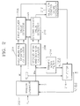
Referring to Figure 1, a first colour converter 100
receives baseband digital colour signals indicated by Rin,
Gin and Bin and converts them into a digital luminance signal
and system-defined colour signals which are indicated by
Yin, Uin and Vin.
Here, R, G and B signals can be converted into
various different colour signals like (Y, I, Q), (Y, U, V)
and (Y, R-Y, B-Y) colour systems according to a signal
processing method. The relationship between the R, G and
B signals and new colour signals Y, U and V can be
expressed by following
equation 1.
In embodiments of the present invention, (Y,U,V) is
defined by a colour system, Y denotes a luminance signal,
and U and V represent system-defined colour signals.
A first function of an image quality enhancing
circuit is to remove impulse noise. First to third noise
reducers 200, 220 and 240 detect an outlier value based on
statistics of samples and trim the result in order to
remove impulse noise, respectively. In other words, the
first to third noise reducers 200, 220 and 240 output the
trimmed mean of a given window when an impulse has been
detected from an input sample, otherwise, bypass the input
sample.
Also, statistics of samples calculated by two windows
of different sizes is useful to reduce detection failure
of the impulse. The detection failure can be an essential
factor of blurring out details of a video signal. The
degree of detection of an outlier value is determined by
a parameter k.
Accordingly, noise reducers 200, 220 and 240 having
independent but identical configurations are employed to
reduce impulse noises of the Yin, Uin, and Vin signals.
However, since a typical digital standard image has
a 4:2:0 format or a 4:2:2 format, a single noise reducer
can be employed instead of the second and third noise
reducers 220 and 240 for Uin and Vin signals. In order to
employ a single noise reduction block, a multiplexer for
selecting the Uin or Vin signals can be installed in front of
the noise reduction block, and a demultiplexer for
separating noise-reduced Uin or Vin signal can be provided in
rear of the noise reduction block.
A main function of the image quality enhancing
circuit is to enhance a contrast using a contrast enhancer
300 based on mean-separate histogram equalization having
gain control and brightness compensation (hereinafter,
referred to as a contrast enhancer).
According to the basic concept of mean-separate
histogram equalization as proposed by the present
invention, a given image is divided into two individual
groups on the basis of the mean value of the given image,
and the divided sub-images are independently equalized.
If the proposed mean-separate histogram equalization
is applied, an abrupt change in brightness and artifects,
which can be generated after a general histogram
equalization when an input image has a concentrated
distributed histogram, can be effectively prevented.
Also, the functions of gain control and brightness
compensation can combine with the mean-separate histogram
equalization. However, other embodiments of histogram
equalization as well as the proposed mean-separate
histogram equalization can be applied in the present
invention.
The brightness compensation can be simply carried out
by mapping a current mean to a desired output mean during
the mean-separate histogram equalization. Also, the gain
control functions to prevent excess contrast enhancement
by controlling the gain of a signal enhanced by the mean-separate
histogram equalization depending on the level of
an input signal.
A local contrast enhancer 400 for sharpness
enhancement detects a local contrast which is defined as
a difference between an input sample value and a
respective low-pass filtered sample values within a
predetermined-size window including the input sample, and
adaptively weights the input sample by applying a weight
value depending on a weighting function to the local
contrast according to the amplitude of the detected local
contrast.
A colour compensator 500 appropriately compensates
for colour signals U and V output by the second and third
noise reducers 220 and 240, according to a luminance
signal Y output by the first noise reducer 200 and a
changed luminance signal Y' output by the local contrast
enhancer 400. The colour compensator 500 maps a current
colour signal put on a given luminance plane to a colour
signal obtained by moving in a colour direction until the
colour signal intersects an enhanced luminance plane in a
RGB space. Consequently, compensated colour signals U'
and V' are output by changing the colour signals U and V
by the same ratio as that of the change of the luminance
signal.
A second colour converter 600 receives the signal Y'
output by the local contrast enhancer 400 and the U' and
V' signals output by the colour compensator 500 and
outputs Rout, Gout and Bout signals through an inverse
processing of the conversion performed by the first colour
converter 100.
The external parameters shown in Figure 1 are useful
and characterize the entire function of the image quality
enhancing circuit, which are a parameter (k) for noise
reduction degree, a parameter (S) for selection of a
recursive/nonrecursive noise reduction mode, gain control
parameters (γu, γL) which are input to the contrast
enhancer 300, a sharpness control parameter (β) which is
input to the local contrast enhancer 400 and a colour
control parameter (α) which is input to the colour
compensator 500.
Figure 2 is a detailed block diagram of the first
noise reducer 200 shown in Figure 1. Here, although the
second and third noise reducers 220 and 240 have the same
configurations, only the first noise reducer 200 for
removing impulse noise of a Yin signal will be described.
Referring to Figure 2, a
window generator 202 outputs
two windows expressed by the following equations, and a
current input sample Y[i][j].
wherein, W
L and W
M are called as large and small windows,
respectively. That is, L1 is greater than M1. The
composition samples of the large and small windows output
by the
window generator 202 vary with a
recursive/nonrecursive noise reduction mode signal (S).
For this explanation, an example of L
1=L
2=2 and M
1=M
2=1 will
be taken.
That is, in case of a nonrecursive noise reduction
mode, 5×5 large window (W
L) and 3×3 small window (W
M)
generated by the
window generator 202 are as follows.
Also, in case of a recursive noise reduction mode, 5X5
large window (W
L) and 3×3 small window (W
M) generated by the
window generator 202 are as follows.
Here, YN[ ][ ] denotes a signal output by the noise
reducer 200 shown in Figure 2 according to the present
invention, i.e., a filtered signal.
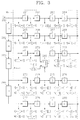
As shown in Figure 3, the detailed circuit diagram of
the window generator 202 is comprised of a plurality of
sample delays 261 to 280, four line delays 281 to 284 and
a multiplexer 285. Here, the multiplexer 285 selects an
input sample Y[i][j] upon the nonrecursive noise reduction
mode and selects a final output signal YN[i][j] output by
a selector 216 upon the recursive noise reduction mode,
according to the external recursive/nonrecursive noise
reduction mode signal (S). Also, D and H denote a sample
delay and a line memory, respectively.
A first mean and
deviation calculator 204 receives
samples of the large window (W
L) generated by the
window
generator 202, obtains a mean sample value (A
L) of the
large window (W
L) using the following equation 8, and
calculates the mean (D
L) of the absolute deviations of the
samples of the large window (W
L) using the
following
equation 9.
A first outlier value detector 206 outputs a first
outlier value detecting signal by determining that an
impulse component is included in the input sample Y[i][j],
when an absolute difference between the input sample
Y[i][j] and the mean sample value (AL) of the large window
(WL) is greater than the mean (kDL) of an absolute
deviation multiplied by a predetermined parameter (k),
i.e.,| Y[i][j]-AL | > kDL. Here, k denotes a noise
reduction parameter.
A second mean and
deviation calculator 208 receives
samples of the small window (W
M) generated by the
window
generator 202, obtains a mean sample value (A
M) of the
small window (W
M) using the following equation 10, and
calculates the mean (D
M) of the absolute deviations of the
samples of the small window (W
M) using the following
equation 11.
A second outlier value detector 210 outputs a second
outlier value detecting signal by determining that an
impulse component is included in the input sample Y[i][j],
when an absolute difference between the input sample
Y[i][j] and the mean sample value (AM) of the small window
(WM) is greater than the mean (kDM) of an absolute
deviation multiplied by the parameter (k), i.e.,
Y[i][j]-AM | > kDM.
A selection control signal generator 212 generates a
selection control signal for selecting the output of a
trimmed mean filter 214 when the first and second outlier
value detecting signals generated by the first and second
outlier value detectors 206 and 210 are all generated,
and, otherwise, bypassing the input sample without change.
Meanwhile, the trimmed
mean filter 214 trims the
sample of the small window W
M generated by the
window
generator 202 using following
equation 12, and outputs an
output signal y
tr[i][j] by taking the mean of residual
samples.
wherein,
and
|T
M| denotes the number of untrimmed samples or the
number of samples which are not determined as outlier
values. An embodiment of the present invention uses the
small window as a trimming window, but the size of the
trimming window is variable.
The selector 216 selects the output signal ytr[i][j] of
the trimmed mean filter 214 according to the selection
control signal generated by the selection control signal
generator 212, i.e., only when the outlier values are
detected in both of the first and second outlier value
detectors 206 and 210. Otherwise, the selector 216
outputs an output signal (Y=YN[i][j]) by bypassing the
input sample Y[i][j] output by the window generator 202
without change. The output signal (Y=YN[i][j]) is fed back
to the window generator 202, and simultaneously output to
the contrast enhancer 300 and the colour compensator 500.
Figure 4 is a detailed block diagram of the contrast
enhancer 300 shown in Figure 1. Referring to Figure 4, a
frame histogram calculator 302 receives a luminance signal
(Y) output by the first noise reducer 200 shown in Figure
1 and calculates a histogram in units of one picture.
That is, the distribution of the gray level of a frame
image is calculated. The picture unit can be a field, but
here is set to be a frame. At this time, an input image
signal {Y} is comprised of L discrete levels represented
by {X0),X1,...,XL-1}.
A frame mean calculator 304 calculates the mean level
(Xm) of the luminance signal output by the first noise
reducer 200 in units of frame. At this time, Xm ∈
{X0,X1,...,XL-1}. A divider 306 divides the gray level
distribution calculated by the frame histogram calculator
302 into the predetermined number (here, two) of subimages
{X}L and {X}U on the basis of the mean level (Xm)
calculated by the frame mean calculator 304, and outputs
probability density functions pL(Xk) and pU(Xk) of two
subimages. The probability density functions pL(Xk) and
pU(Xk) can be calculated by following equations 13 and 14.
pL (Xk ) = n L k n L , for k = 0, 1,...,m
pU (Xk ) = n u k n u , for k = m+1, m+2,..., L-1
wherein L is the number of levels, pL(Xk) is a probability
of a k-th gray level (Xk) in the subimage {X}L, pU(Xk) is a
probability of a k-th gray level (Xk) in the subimage {X}U, n L / k and n U / k denote the numbers of times in which the level
Xk appears in each subimage, and nL and nU are the numbers
of the respective entire samples in the subimages {X}L and
{X}U.
A
first CDF calculator 308 receives the probability
density functions p
L(X
k) of a subimage (hereinafter, called
as a first subimage) having samples all being lower than
or equal to the mean level (X
m) from the
divider 306 and
calculates a cumulative density function (CDF) c
L(X
k) using
following equation 15.
A
second CDF calculator 310 receives the probability
density functions p
U(X
k) of a subimage (hereinafter, called
as a second subimage) having samples all being greater
than the mean level (X
m) from the
divider 306 and
calculates a cumulative density function c
U(X
k) using
following equation 16.
A CDF memory 312 renews the cumulative density
functions cL(Xk) and cU(Xk) calculated by the first and
second CDF calculators 308 and 310 in frame units
according to a synchronous signal (SYNC), and provides the
previously stored prior-to-one-frame cumulative density
functions cL(Xk) and cU(Xk) to first and second mappers 316
and 318 during renewal, respectively. Here, the
synchronous signal is a field synchronous signal when the
picture unit is a field, and is a frame synchronous signal
when it is a frame. The CDF memory 312 is used as a
buffer.
Meanwhile, a brightness compensator 314 receives the
mean level (Xm) output by the frame mean calculator 304,
adds a corrected value (Δ) depending on the mean
brightness of a signal input to the contrast enhancer 300
to the mean level (Xm) as shown in following equation 17,
and outputs a compensated mean level (Bm).
Bm = Xm + Δ
That is, when Bm is a compensated mean level and Δ is
a corrected value obtained by a predetermined correction
function depending on a mean brightness, the compensated
mean level (Bm) becomes a result obtained by adding the
corrected value (Δ) to the mean level (Xm). At this time,
Bm ⊂ {X0,X1,...,XL-1}.
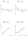
The corrected value (Δ) is determined by correction
functions shown in Figures 5a and 5b. The present
invention is not limited to such examples as the
correction functions shown in Figures 5a and 5b, and other
application examples can exist.
The brightness of enhanced signal (Yo) is controlled
by the corrected value depending on the correction
functions shown in Figures 5a and 5b. That is, when the
mean level (Xm) is very small, i.e., when an image is very
dark, a corrected value (Δ) being larger than 0 is added
to the mean level (Xm), and the mean-separate histogram
equalization proposed by the present invention is then
performed, whereby the mean brightness of the enhanced
signal (Yo) becomes high.
Also, when the mean level (Xm) is very large, i.e.,
when an image is very bright, a corrected value (Δ) being
smaller than 0 is added to the mean level (Xm), and the
mean-separate histogram equalization proposed by the
present invention is then performed, whereby the mean
brightness of the enhanced signal (Yo) becomes low.
Accordingly, when the mean-separate histogram equalization
is performed using the mean level (Bm) compensated by a
predetermined appropriate corrected value (Δ) according to
the mean level (Xm), the image quality of an input image
can be remarkably enhanced.
Figures 6a and 6b show the relationship between the
mean level (Xm) and the compensated mean level (Bm) to
which a corrected value (A) depending on the brightness
correction function shown in Figures 5a and 5b is added.
Meanwhile, the first mapper 316 shown in Figure 4
receives the cumulative density function cL(Xk) calculated
by the first CDF calculator 308, the signal (Xk) output
from the first noise reducer 200, and the compensated mean
level (Bm) output by the brightness compensator 314, and
maps the samples {X}L of the first subimage to a gray level
ranging from 0 to Bm according to the cumulative density
function.
The second mapper 318 receives the cumulative density
function cU(Xk) calculated by the second CDF calculator
310, the signal (Xk) output by the first noise reducer 200,
and the compensated mean level (Bm) output by the
brightness compensator 314, and maps the samples {X}U of
the second subimage to a gray level ranging from Bm' to XL-1
according to the cumulative density function.
The outputs mapped by the first and
second mappers
316 and 318 are expressed by following equation 18, and B
m'
is expressed by following equation 19.
B m ' = Bm + XL -1/(L-1)
wherein B
m' denotes a first gray level which is mapped in
a higher region than the compensated mean level (B
m).
Accordingly, the equation 18 shows the results of
mapping input samples to (0,Bm) when they are equal to or
smaller than the mean level (Xm) and mapping the input
samples to (Bm',XL-1) when they are larger than the mean
level (Xm).
Also, when a corrected value is larger than 0 (i.e.,
Δ > 0), the equalized output (Yo) becomes bright, and when
it is smaller than 0 (i.e., Δ < 0), the equalized output
(Yo) becomes dark. As the Δ increases, a dynamic range at
a lower region will be enhanced, and as the Δ decreases,
a dynamic range at an upper region will be enhanced. A
predetermined appropriate compensated mean level (Bm)
depending on the mean level (Xm) greatly enhances the image
quality of an input image.
A comparator 320 compares the signal (Xk) output by
the first noise reducer 200 with the mean level (Xm) output
by the frame mean calculator 304 and generates a selection
control signal. A first selector 322 selects the first
mapper 316 when the signal (Xk) output by the first noise
reducer 200 is lower than the mean level (Xm), and
otherwise, selects the second mapper 318.
Here, the signal (Xk) input to the first and second
mappers 316 and 318 is a signal of the frame next to a
frame corresponding to the cumulative density function
value output by the CDF memory 312. Thus, a frame memory
for delaying a signal output by the first noise reducer
200 by one frame can be additionally provided to input a
signal of the same frame as that of the cumulative density
function output by the CDF memory 312 to the first and
second mappers 316 and 318. However, the frame memory can
be omitted using the characteristic that there is a high
correlation between adjacent frames, so that hardware is
reduced.
Furthermore, without separately using the frame
histogram calculator 302 and the CDF calculators 308 and
310, the gray level distribution of an image signal of
each subgroup by the CDF calculators 308 and 310 without
the frame histogram calculator 302 is calculated, and a
CDF can be calculated on the basis of the result.
Meanwhile, a subtracter 324 and an adder 334 perform
a function of controlling the gain of the enhanced signal
(Yo). Here, a basic concept of the gain control is that
a variation of the maximum gray level of an input signal
(Y) is restricted according to the degree of contrast
enhancement when a contrast is enhanced using the mean-separate
histogram equalization.
First, the relationship between the input signal
(Y=Xk) and the enhanced signal (Yo) will be expressed by
following equation 20 or 21;
Yo = Xk + Δk
or
Yo - Xk = Δk
wherein Δk is the amount of variation (the degree of
enhancement) made by the mean-separate histogram
equalization when an input sample is Xk, i.e., a difference
between the level of the input signal (Y=Xk) and the level
(Yo) mapped to a new gray level by the mean-separate
histogram equalization.
In order to prevent excess enhancement due to
histogram equalization, the amount of variation Δk
according to the present invention is restricted as
follows.
Δk ≤ γ · g(Xk)
wherein g(Xk) denotes a maximum bounding function, the
g(Xk) is a function of the input signal (Y=Xk) and always
has a positive value (i.e., g(Xk)≥0), and γ(γ≥0) is a gain
control parameter. The above equation 22 can be expressed
by following equation 23 as the same equation.
-r g(Xk) ≤ Δi ≤ r·g(Xk)
The concept of restricting the amount of variation Δk
expressed as the equation 22 is related to the Weber's
ratio. In fact, if g(Xk) is equal to Xk, the following
equation 24 can be obtained from the above equation 22.
Δ k Xk ≤γ
wherein
Δ k X k
is the amount corresponding to the Weber's ratio. The
Weber's ratio is an experimental fact that human beings
feel that, when X1 is changed by γX1 and X2 is changed by
γX2, the degrees of the variations are the same. Thus, the
concept of the gain control applied to the present
invention is to control the gain, i.e., the enhancement
degree of an enhanced signal using the mean-separate
histogram having a brightness compensating function on the
basis of the Weber's ratio.
The subtracter 324 shown in Figure 4 subtracts the
input signal (Y=Xk) output by the first noise reducer 200
from the enhanced signal (Yo) output by the first selector
322 and obtains the amount of variation (Δk) made by the
mean-separate histogram equalization having the brightness
compensation function.
A gain feature determiner 326 restricts enhancement
of the input signal (Xk) by outputting a maximum bounding
function g(Xk) being a function of the input signal (Xk).
For instance, when the g(Xk) is K1 and the K1 is a
constant, the g(Xk) restricts input enhancement by
identical amount regardless of an input gray level value.
The maximum bounding function g(Xk) can be equal to aXk or a Xk
(here, a is a constant), and differently restricts the
enhanced amount of an input image according to the input
gray level value.
A second selector 328 compares the input signal (Xk)
with the mean level (Xm) output by the frame mean
calculator 304, and selects a first gain control parameter
(γL) when the input signal (Xk) is lower than or equal to
the mean level (Xm) and otherwise, selects a second gain
control parameter (γU). Here, the first gain control
parameter (γL) is a parameter for a first subimage signal,
and the second gain control parameter (γU) is a parameter
for a second subimage signal. Here, the first and second
gain control parameters (γL) and (γU) can be given as the
same value to the input signal in contrast that different
gain control parameters are provided to each subimage.
A multiplier 330 multiplies the value of the maximum
bounding function g(Xk) output by the gain feature
determiner 326 by a gain control parameter (γ) selected by
the second selector 328 and outputs a limit value (γ ·
g(Xk)). Here, the limit value γ · g(Xk) is a
characteristic of the gain control according to the
present invention.
A
limiter 332 compares the variation amount (Δ
k)
output by the
subtracter 324 with the limit value γ · g(X
k)
output by the
multiplier 330, restricts the variation
amount (Δ
k), and outputs a restricted variation amount
(Δ
k') like the following equation 25.
That is, when an absolute value of the variation
amount (Δk) is equal to or smaller than γ · g(Xk), the
variation amount (Δk) is used as the restricted variation
amount (Δk'). When the variation amount (Δk) is greater
than γ · g(Xk), the variation amount (Δk) is restricted to
the γ · g(Xk). When the variation amount (Δk) is smaller
than -γ · g(Xk), the variation amount (Δk) is restricted to
the -γ · g(Xk), thereby controlling the gain of the
enhanced signal (Yo).
The adder 334 adds the input signal (Xk) to the
restricted variation amount (Δk') output by the limiter 332
and outputs an output signal (YH) as shown in the following
equation 26. Thus, the final output signal (YH) of the
contrast enhancer 300 can be expressed as follows.
YH = Xk + Δ k '
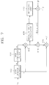
Figure 7 is a detailed block diagram of the
local
contrast enhancer 400 shown in Figure 1, wherein an M×
N
window generator 402 receiving the output (Y
H) of the
contrast enhancer 300 shown in Figure 1 generates an M×N
window (W) which can be expressed by the following
equation 27, and outputs it to an M×N low-pass filter
(LPF) 404.
Also, a middle sample (x) of a center line of the M×N
window (W) is input to a subtracter 406 and an adder 416.
Here, the middle sample (x) of the center line is an input
sample for improving a contrast.
Figure 8 is a detailed circuit diagram of the M×
N
window generator 402 when both M and N are equal to 3.
Referring to Figure 8, D and H denote a sample delay and
a line memory, respectively. The output signal (m) of the
M×
N LPF 404 shown in Figure 7 can be represented by the
following equation 28.
wherein b
ij is a predetermined coefficient, and
corresponds to an impulse response of the M×
NLPF 404.
A subtracter 406 subtracts the output signal (m) of
the M×N LPF 404 from the middle sample value (x). An
absolute value calculator 408 calculates an absolute value
of the output of the subtracter 406, and a weighting unit
410 outputs a value obtained by weighting the output of
the absolute value calculator 408 using a predetermined
weighting function f(|x-m|). A first multiplier 412
multiplies a predetermined parameter (β) by the output of
the weighting unit 410.
A second multiplier 414 multiplies the output of the
subtracter 406 by the output of the first multiplier 412
and outputs the multiplied result β·f(|x-m|) (x-m). An
adder 416 adds the multiplied result to the middle sample
(x) of the M×N window generator 402.
At this time, a difference between the middle sample
(x) of the M×Nwindow generator 402 and the output signal
(m) of the M×N LPF 404 can be defined as a contrast
visually felt by a human being, i.e., a local contrast.
In other words, a place where the value |x-m| is large can
be called a region having a high contrast, and a place
where the value |x-m| is small can be called a region
having a low contrast. The local contrast is enhanced by
amplifying the value |x-m| by f(|x-m|) according to the
above-defined local contrast and adding the result to the
original signal (x). The output (Y') of the adder 416
will be expressed by following equation 29.
Y' = x + β·f(|x-m|) (x-m)
wherein the function f() being a weighting function is a
function of f|x-m|. Various types of enhancement
characteristics for the local contrast can be realized by
appropriately selecting a weighting function. Also, β is
a parameter for adjusting the amount of enhancement of an
entire local contrast.
For example, when f(|x-m|) equals 0, Y' equals x,
i.e., there is no contrast enhancement effect. Thus,
given that when |x-m| is smaller than T, f(|x-m|) is K2,
and that when |x-m| is greater than T, f(|x-m|) is
0,(here, T and K2 are constants), the local contrast is
amplified by K2 times in a region where the local contrast
is small (i.e., |x-m| < T). On the other hand, in a
region where it is already determined that the local
contrast is large, adaptive local contrast enhancement of
bypassing an input sample is performed.
Figure 9 show examples of a weighting function for
determining a weighted value of a local contrast according
to |x-m|. Various contrast enhancement characteristics
can be obtained by using the weighting functions indicated
by (a) and (b).
Meanwhile, a colour compensation method will be
described with reference to Figures 10 and 11 before
describing the colour compensator 500 shown in Figure 1.
A colour signal C is given as R, G and B signals, the
luminance signal Y shown in the equation 1 is given as
a1R+a2G+a3B, and Y is converted into Y' through the
contrast enhancer 300 and the local contrast enhancer 400.
At this time, the object of the colour compensation is to
properly change the original colour signal C=(R,G,B)
according to the change of Y to Y'.
The basic concept of the colour compensation
according to the present invention is to change a given
colour to the colour direction in a (R,G,B) space.
First, where Y equals a1R+a2G+a3B, R, G and B each
having a constant value Y form a plane in the (R,G,B)
space. That is, every colour signal put on the plane
where Y equals a1R+a2G+a3B has an identical luminance
value. The change of luminance from Y to Y' involves the
fact that the given colour C is moved to a position on the
Y' plane as shown in Figure 10. At this time, in the
present invention, suppose that the colours C and C' have
the same colour direction. Here, when C' equals
(R',G',B'), it means that a straight line OC coincides
with a straight line OC'. Thus, the compensated colour C'
on the Y' plane is obtained by detecting an intersecting
point of the straight line OC and the Y' plane. Briefly,
the original colour signal C shown in Figure 10 is mapped
into the new colour signal C' when the luminance value is
changed from Y to Y', which is the intersecting point of
the straight line OC and the Y' plane.
Now, (l,m,n) is defined as a directional cosine of
the given colour C in order to obtain the colour C', which
will be expressed by following equation 30;
l = R/r, m = G/r, n = B/r,
wherein r equals R 2+ G 2+ B 2 . Similarly, the directional
cosines l', m' and n' of the output colour signals R', G'
and B' can be expressed by following equation 31;
l' = R'/r', m' = G'/r', n' = B'/r',
wherein r' equals R' 2+G' 2+B' 2 . To make the two types
of colours have the same colour direction, the
relationships shown in following equations 32 and 33
should be accomplished.
l = l', m = m', n =n'
R'/r' = R/r, G'/r' = G/r, B'/r' = B/r
Accordingly, the following equations 34, 35 and 36 are
obtained.
R'= r' r R
G'= r' r G
B'= r' r B
When the relationships given by equations 34, 35 and 36
are substituted for Y'=a1R'+awG'+a3B', following equations
37, 38 and 39 are obtained;
Y' = a 1 r' r R + a 2 r' r G + a 3 r' r B
Y' = r' r (a 1 R + a 2 G + a 3 B)
Y' = r' r Y
Accordingly, such a result as the following equation
40 is obtained.
Y' Y = r' r
Meanwhile, Equations 34 through 36 can be also
expressed as following Equations 41 through 53 by using
the result of the Equation 40.
R' = Y' Y R
G' = Y' Y G
B' = Y' Y B
Consequently, C' can be obtained as follows.
C' = (R' ,G' ,B')
C' = (qR,qG,qB)
wherein q equals Y'/Y which is a ratio between the
original luminance signal and the resultant luminance
signal. Since this means that the ratio of a luminance
change is equal to that of a colour change, the present
invention performs colour compensation by changing a
colour value according to the luminance change.
The colour compensation can be easily performed on
other colour systems using the result of Equation 45.
That is, for instance, the (Y,U,V) signals given in
Equation 1, being the results of the colour compensation
given in Equation 45, should be converted into (qY,qU,qV)
as shown in following Equations 46 to 51:
U' = b1R' + b2G' + b3B'
U = q(b1R + b2G + b3B)
U = qU
and,
V' = c1R' + c2G' + c3B'
V = q(c1R + c2G + c3B)
V = qV
Now, colour compensation will be performed to prevent
colour saturation due to the above-described image quality
enhancement method.
The luminance ratio is given as q, and when the
colour compensation is made by a compensating line
(R',G',B')=q(R,G,B) shown in Figure 11, a colour signal
between a b(=Max/q) level and a maximum (Max) level is
compensated to a maximum value (Max), which involves being
saturated. That is because the colours between b and Max
are consequently mapped to the Max and are not
distinguished from each other, referring to the above-described
compensating method.
In order to prevent the colour saturation, the
compensating line (R',G',B')=q(R,G,B) is approximated to
a compensating line (R',G',B')=A(R,G,B)+K, for a colour
signal between a(=αb) level and a maximum level (Max).
Here, a parameter (α) is greater than or equal to 0 and
lower than or equal to 1, and A and K can be expressed by
following Equations 52 and 53;
A = q 1-α q-1
and,
K = q-1α q-1 Max
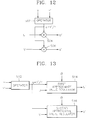
Figure 12 is a detailed circuit diagram of the colour
compensator 500 shown in Figure 1 according to an
embodiment of the present invention, wherein an operator
502 operates a ratio (q) between a signal Y output by the
first noise reducer 200 of Figure 1 and a signal Y' output
by the local contrast enhancer 400, i.e., the Y'/Y.
A first multiplier 504 multiplies a signal U output
by the second noise reducer 220 of Figure 1 by the ratio
(q) output by the operator 502 and outputs a signal U'.
A second multiplier 506 multiplies a signal V output by
the third noise reducer 240 of Figure 1 by the ratio (q)
output by the operator 502 and outputs a signal V'.
Figure 13 is a detailed circuit diagram of the colour
compensator 500 shown in Figure 1 according to another
embodiment of the present invention, wherein an operator
512 operates a ratio (q) between a signal Y output by the
first noise reducer 200 of Figure 1 and a signal Y' output
by the local contrast enhancer 400, i.e., the Y'/Y.
First approximate value regulators 514 and 516 are
provided to prevent colour compensation using the
approximated compensating line shown in Figure 11. The
first approximate value regulator 514 receives the signal
U output by the second noise reducer 220 of Figure 1, the
ratio (q) output by the operator 512, and a parameter (α),
and outputs a signal U' compensated by the compensating
line (R',G',B')=q(R,G,B) when the input signal U is
between the minimum level and the a(=αb) level and outputs
a signal U' compensated by the approximated compensating
line (R',G',B')=A(R,G,B)+K when the input signal U is
between the "a" level and the maximum level (Max).
At this time, the signal U can be compensated either
by the compensating line (R',G',B')=q(R,G,B) or by the
approximated compensating line (R',G',B')=A(R,G,B)+K,
depending on the parameter value (a). That is, when the
parameter value (α) is 1, the signal U is compensated by
the compensating line (R',G',B')=q(R,G,B). When the
parameter value (α) is greater than 0 and smaller than 1,
the signal U being between the minimum level and
the"a"(=αb) level is compensated by the compensating line
(R',G',B')=q(R,G,B), and the signal U being between the
"a" level and the maximum level is compensated by the
approximated compensating line (R',G',B')=A(R,G,B)+K.
The second approximate value regulator 516 receives
the signal V output by the third noise reducer 240 of
Figure 1, the ratio (q) output by the operator 512, and a
parameter (α), and outputs a signal V' compensated by the
compensating line (R',G',B')=q(R,G,B) when the input
signal V is between the minimum level and the "a" level
and outputs a signal V' compensated by the approximated
compensating line (R',G',B')=A(R,G,B)+K when the input
signal V is between the "a" level and the maximum level
(Max).
Thus, embodiments of the present invention are
applicable to a wide-ranging field associated with image
quality enhancement for an image signal. That is, the
present invention can be applied to broadcasting
apparatuses, radar signal processing systems, medical
equipment, electric home appliances, etc.
As described above, embodiments of the present
invention, which considers a corrected value depending on
the mean brightness of an input image and uses the mean-separate
histogram equalization having the gain control
function for preventing excessive enhancement, effectively
reduce an abrupt change in brightness and an artifact
generated during conventional histogram equalization,
thereby enhancing a contrast and greatly improving the
image quality of an input image. Furthermore, embodiments
of the present invention effectively remove impulse noise
by increasing reliability through a dual impulse detecting
method, thus improving the image quality. The image
quality can also be enhanced through enhancement of a
local contrast. Also, when a luminance is changed by a
predetermined process for contrast enhancement,
embodiments of the present invention vary a colour value
according to the change, thereby providing an undistorted
colour signal.
The reader's attention is directed to all papers and
documents which are filed concurrently with or previous to
this specification in connection with this application and
which are open to public inspection with this
specification, and the contents of all such papers and
documents are incorporated herein by reference.
All of the features disclosed in this specification
(including any accompanying claims, abstract and
drawings), and/or all of the steps of any method or
process so disclosed, may be combined in any combination,
except combinations where at least some of such features
and/or steps are mutually exclusive.
Each feature disclosed in this specification
(including any accompanying claims, abstract and
drawings), may be replaced by alternative features serving
the same, equivalent or similar purpose, unless expressly
stated otherwise. Thus, unless expressly stated
otherwise, each feature disclosed is one example only of
a generic series of equivalent or similar features.
The invention is not restricted to the details of the
foregoing embodiment(s). The invention extends to any
novel one, or any novel combination, of the features
disclosed in this specification (including any
accompanying claims, abstract and drawings), or to any
novel one, or any novel combination, of the steps of any
method or process so disclosed.