EP0832703A1 - Verfahren zur Herstellung metallischer Bauteile mit Innengewinden und Maschine dafür - Google Patents
Verfahren zur Herstellung metallischer Bauteile mit Innengewinden und Maschine dafür Download PDFInfo
- Publication number
- EP0832703A1 EP0832703A1 EP97106383A EP97106383A EP0832703A1 EP 0832703 A1 EP0832703 A1 EP 0832703A1 EP 97106383 A EP97106383 A EP 97106383A EP 97106383 A EP97106383 A EP 97106383A EP 0832703 A1 EP0832703 A1 EP 0832703A1
- Authority
- EP
- European Patent Office
- Prior art keywords
- core bar
- male thread
- thread section
- section
- internal threads
- Prior art date
- Legal status (The legal status is an assumption and is not a legal conclusion. Google has not performed a legal analysis and makes no representation as to the accuracy of the status listed.)
- Ceased
Links
- 239000002184 metal Substances 0.000 title claims abstract description 38
- 238000004519 manufacturing process Methods 0.000 title claims abstract description 10
- 238000003825 pressing Methods 0.000 claims description 11
- 239000007769 metal material Substances 0.000 description 15
- 238000000034 method Methods 0.000 description 2
- 239000000463 material Substances 0.000 description 1
Images


Classifications
-
- F—MECHANICAL ENGINEERING; LIGHTING; HEATING; WEAPONS; BLASTING
- F16—ENGINEERING ELEMENTS AND UNITS; GENERAL MEASURES FOR PRODUCING AND MAINTAINING EFFECTIVE FUNCTIONING OF MACHINES OR INSTALLATIONS; THERMAL INSULATION IN GENERAL
- F16B—DEVICES FOR FASTENING OR SECURING CONSTRUCTIONAL ELEMENTS OR MACHINE PARTS TOGETHER, e.g. NAILS, BOLTS, CIRCLIPS, CLAMPS, CLIPS OR WEDGES; JOINTS OR JOINTING
- F16B39/00—Locking of screws, bolts or nuts
- F16B39/22—Locking of screws, bolts or nuts in which the locking takes place during screwing down or tightening
- F16B39/28—Locking of screws, bolts or nuts in which the locking takes place during screwing down or tightening by special members on, or shape of, the nut or bolt
- F16B39/284—Locking by means of elastic deformation
-
- B—PERFORMING OPERATIONS; TRANSPORTING
- B21—MECHANICAL METAL-WORKING WITHOUT ESSENTIALLY REMOVING MATERIAL; PUNCHING METAL
- B21K—MAKING FORGED OR PRESSED METAL PRODUCTS, e.g. HORSE-SHOES, RIVETS, BOLTS OR WHEELS
- B21K1/00—Making machine elements
- B21K1/56—Making machine elements screw-threaded elements
Definitions
- the present invention relates to a method for producing metal parts having internal threads and a machine therefor.
- Fig. 6 to Fig. 8 show a rivet nut 1 and its production method described in British Patent No. 1,439,811.
- a thread ridge 3 is formed on the inner wall of a shaft 2. This thread ridge 3 is formed of six intermittent low thread ridge portions 4.
- the rivet nut 1 is produced by inserting a core bar 7 into the shaft 2, pressing the shaft 2 toward the core bar 7 by a jaw 10 provided on the outer periphery of the shaft 2 with the leading end of the shaft 2 kept in contact with a stopper 9, thereby transferring thread ridges 8 of the core bar 7 to the inner wall of the shaft 2.
- this method for producing the rivet nut 1 needs to twist the core bar 7 to remove the core bar 7 because the shaft 2 is closely adhered to the thread ridges 8 of the core bar 7 by pressing the jaw 10 against the shaft 2.
- threads 25, 26 are intermittent threads but threads 28 are positioned along the circumference of a nut 10, so that the core bar cannot be removed by squeezing, and it is necessary to cut the threads.
- Swedish Patent No. 169,556 does not disclose about the removal of the core bar.
- the core bar and the jaw may be designed to be disassembable, but it becomes difficult to align the product pitch and not practical.
- the present invention has been completed to remedy the above existing disadvantages, and aims to provide a method and machine for producing metal parts having internal threads which can be removed readily from a core bar without turning the formed metal parts having internal threads.
- the invention of claim 1 comprises the steps of inserting a second core bar axially into the center of a first core bar which is axially divided into a multiple number and has a male thread section on its outer periphery; putting a metal cylinder on the male thread section of the first core bar; applying a pressure by a plurality of punches to the outer periphery of the metal cylinder in a centripetal direction to deform the metal cylinder to transfer the male thread section of the first core bar to the inner wall of the metal cylinder to form a female thread section; removing the second core bar which has been axially inserted into the center of the first core bar from the male thread section; and contracting the diameter of the male thread section of the first core bar in a centripetal direction to enable the removal of the metal cylinder having the female thread section formed therein without twisting.
- the invention of claim 2 relates to a method for producing a metal part having internal threads according to claim 1, wherein when the female threads are formed, the second core bar is tightly adhered axially to the inner wall of the first core bar, the first core bar is served as a rigid body to form the female threads, and the second core bar is removed from the male thread section, the diameter of the male thread section of the first core bar is contracted in the centripetal direction to make a thread ridge diameter of the male thread section of the first core bar smaller than that of the formed female threads.
- the invention of claim 3 comprises a first core bar which is axially divided into a multiple number and has a male thread section formed on its outer periphery; a second core bar which is axially inserted into the center of the first core bar; a plurality of punches which are provided around the male threshold section of the first core bar; and a pressing tool which is provided on the outer periphery of the first core bar and contracts the diameter of the male thread section of the first core bar in a centripetal direction.
- the invention of claim 4 relates to a machine for producing a metal part having internal threads according to claim 3, wherein the first core bar has a base having a through hole, and a male thread core bar member which is interconnected with the base, formed via slits which are disposed parallel to an axis and equal in a radial direction and has a male thread section formed on the outer periphery of its leading end.
- each male thread core bar member has a male thread section, a sloped section and an elastic deformable section for contracting the male thread section.
- the invention of claim 6 relates to a machine for producing a metal part having internal threads according to any one of claim 3 through claim 5, wherein the pressing tool is made of a ring-shaped member having a sloped inner wall corresponding to the sloped section of the male thread core bar member of the first core bar.
- a second core bar is axially inserted in the center of a first core bar which is axially divided into a multiple number and formed a male thread section on the outer periphery.
- the second core bar can be tightly adhered axially to the inner wall of the first core bar and the first core bar can be served as a rigid body while female threads are being formed.
- a metal cylinder is put on the male thread section of the first core bar.
- the outer periphery of the metal cylinder is pressed in a centripetal direction by a plurality of punches to deform the metal cylinder and the male thread section of the first core bar is transferred to form a female thread section on the inner wall of the metal cylinder.
- the second core bar which was axially inserted in the center of the first core bar is removed from the male thread section.
- the second core bar is removed from the male thread area, the diameter of the male thread section of the first core bar is contracted in a centripetal direction, and the thread ridge diameter of the male thread section of the first core bar can be contracted to be smaller than that of the formed female threads.
- the male thread section of the first core bar is contracted in the centripetal direction, and the metal cylinder which has the female thread section formed on its inner wall can be removed without twisting.
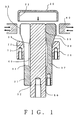
- Fig. 1 is a vertical sectional view showing a state immediately before processing a cup-shaped metal material 20.
- Fig. 2 is a plane view of a first core bar of Fig. 1.
- Fig. 3 is a vertical sectional view of a first core bar of Fig. 1.
- Fig. 4 is a vertical sectional view showing a state of processing the cup-shaped metal material 20.
- Fig. 5 is a vertical sectional view showing a state of removing the cup-shaped metal material 20 having the internal threads formed.
- Fig. 6 is a transverse sectional view showing a rivet nut as an example having conventional internal threads formed.
- Fig. 7 is a vertical sectional view of the rivet nut of Fig. 6.
- Fig. 8 is a sectional view showing a method for producing the rivet nut of Fig. 6.
- Fig. 1 to Fig. 5 show one embodiment in that the method and machine for producing a metal part having internal threads described in claims 1 to 6 is applied to a cup-shaped metal material 20.
- a first core bar 30 has a base 31 having a through hole 32, and a male thread core bar member 33 which is interconnected with the base 31, formed via six slits 34 which are disposed parallel to an axis and equal in a radial direction and has a male thread section 35 formed on the outer periphery of its leading end.
- Each male thread core bar member 33 has the male thread section 35, a sloped section 36, and an elastic deformable section 37 for contracting the male thread section from its leading end to the base 31.
- a through hole which is concentric with the through hole 32 of the base 31 is axially formed at the center of the respective male thread core bar member 33.
- An inner wall 38 of the male thread section 35 has a diameter equal to the through hole 32, and an inner wall 39 of the sloped section 36 and an inner wall 40 of the elastic deformable section 37 have a diameter larger than the through hole 32.
- the inner wall 40 of the elastic deformable section 37 has a diameter larger than that of the inner wall 39 of the sloped section 36.
- the elastic deformable section 37 is the thinnest section in the male thread core bar member 33 and can be deflected when exposed to an external force.
- the sloped section 36 serves to connect the male thread section 35 and the elastic deformable section 37 and to engage with a sloped bore of a ring member to be described afterward.
- the first core bar 30 has the male thread section 35 divided by the six slits 34 which are disposed parallel to an axis and equal in a radial direction but integrally formed as the core bar.
- the first core bar 30 is mounted on a production machine with the base 31 as a mounting part .
- a second core bar 50 is a bar material having almost the same diameter as the through hole 32. And, it is mounted on a machine independent of the one for the first core bar 30 and can be moved solely.
- a pressing tool 70 is provided on the outer periphery of the first core bar 30.
- the pressing tool 70 is formed of a ring-shaped member 71 having a sloped inner wall 72 corresponding to the sloped section 36 of the male thread core bar member 33 of the first core bar 30.
- This ring-shaped member 71 is operated by a drive source such as a hydraulic cylinder.
- Fig. 1 shows a state of the cup-shaped metal material 20 immediately before processing.
- the second core bar 50 is axially inserted into the center of the first core bar 30. Accordingly, to form female threads, the second core bar 50 can be tightly adhered axially to the inner wall 38 of the first core bar 30, and the first core bar 30 can be used as a rigid body.
- the cup-shaped metal material 20 is put on the male thread section 35 of the first core bar 30 as shown in Fig. 4. Then, the outer periphery of the cup-shaped metal material 20 is pressed in a centripetal direction by the six punches 60 to deform the cup-shaped metal material 20 and to transfer the male thread section 35 of the first core bar 30 to the inner wall 21 of the cup-shaped metal material 20, thereby forming a female thread section 22.
- the ring-shaped member 71 is moved by a hydraulic cylinder (not shown) toward the sloped section 36 of the male thread core bar member 33 of the first core bar 30, and the sloped inner wall 72 is pushed along the sloped section 36.
- the male thread core bar member 33 can have the elastic deformable section 37 deflected to contract the diameter of the male thread section 35 in a centripetal direction, and a thread ridge diameter 41 of the male thread section 35 of the first core bar 30 can be made smaller than a thread ridge diameter 23 of the formed female thread section 22.
- the cup-shaped metal material 20 having the female thread section 22 formed therein can be disengaged from the first core bar 30 without making a relative turning. In other words, the cup-shaped metal material 20 having the female thread section 22 formed therein can be removed without twisting.
- the pressing tool 70 is returned to the state as shown in Fig. 1. Accordingly, it is made ready for the next processing.
- the slits are preferably formed in a large number to facilitate the operation by the pressing tool 70, but their number is desirably 6 to 8 in view of the processing steps.
- the number of punches 50 may be increased or reduced depending on the number of the male thread sections 35.
- the first core bar is formed of a single body, there is no possibility of having a disadvantage that the obtained internal threads have a mismatching pitch.
Applications Claiming Priority (2)
| Application Number | Priority Date | Filing Date | Title |
|---|---|---|---|
| JP8258898A JPH1099931A (ja) | 1996-09-30 | 1996-09-30 | 内螺子を有する金属製部品の製造方法及びその装置 |
| JP258898/96 | 1996-09-30 |
Publications (1)
| Publication Number | Publication Date |
|---|---|
| EP0832703A1 true EP0832703A1 (de) | 1998-04-01 |
Family
ID=17326572
Family Applications (1)
| Application Number | Title | Priority Date | Filing Date |
|---|---|---|---|
| EP97106383A Ceased EP0832703A1 (de) | 1996-09-30 | 1997-04-17 | Verfahren zur Herstellung metallischer Bauteile mit Innengewinden und Maschine dafür |
Country Status (6)
| Country | Link |
|---|---|
| EP (1) | EP0832703A1 (de) |
| JP (1) | JPH1099931A (de) |
| KR (1) | KR19980024022A (de) |
| AU (1) | AU3933297A (de) |
| CA (1) | CA2203983A1 (de) |
| TW (1) | TW325509B (de) |
Cited By (2)
| Publication number | Priority date | Publication date | Assignee | Title |
|---|---|---|---|---|
| DE102008063690A1 (de) * | 2008-12-19 | 2010-07-08 | Ifm Electronic Gmbh | Verfahren und Vorrichtung zur Erzeugung eines Gewindes auf einer Hülse |
| DE102014017808B3 (de) * | 2014-12-03 | 2016-02-25 | Audi Ag | Vorrichtung und Verfahren zur spanlosen Innengewindeformung |
Families Citing this family (2)
| Publication number | Priority date | Publication date | Assignee | Title |
|---|---|---|---|---|
| CN102814616B (zh) * | 2012-08-30 | 2015-11-18 | 无锡迈鑫科技实业有限公司 | 牙形矫正器 |
| CN112893721B (zh) * | 2021-01-15 | 2022-03-22 | 西安交通大学 | 差动式行星滚柱丝杠螺母分瓣模具滚轧成形装置及工艺 |
Citations (3)
| Publication number | Priority date | Publication date | Assignee | Title |
|---|---|---|---|---|
| NL7901892A (nl) * | 1979-03-08 | 1980-09-10 | Erico Europa | Werkwijze en matrijs voor het vormen van inwendige zelfremmende schroefdraad. |
| DE3200755A1 (de) * | 1982-01-13 | 1984-04-26 | Helmut 2420 Eutin Krueger-Beuster | Spreizgewindeformer |
| WO1993009896A1 (de) * | 1991-11-19 | 1993-05-27 | Fraunhofer-Gesellschaft zur Förderung der angewandten Forschung e.V. | Werkzeug zur spanlosen herstellung von aussen- oder innenkonturen |
-
1996
- 1996-09-30 JP JP8258898A patent/JPH1099931A/ja active Pending
-
1997
- 1997-04-16 TW TW086104927A patent/TW325509B/zh active
- 1997-04-17 EP EP97106383A patent/EP0832703A1/de not_active Ceased
- 1997-04-29 CA CA002203983A patent/CA2203983A1/en not_active Abandoned
- 1997-05-15 KR KR1019970018735A patent/KR19980024022A/ko not_active Application Discontinuation
- 1997-09-30 AU AU39332/97A patent/AU3933297A/en not_active Abandoned
Patent Citations (3)
| Publication number | Priority date | Publication date | Assignee | Title |
|---|---|---|---|---|
| NL7901892A (nl) * | 1979-03-08 | 1980-09-10 | Erico Europa | Werkwijze en matrijs voor het vormen van inwendige zelfremmende schroefdraad. |
| DE3200755A1 (de) * | 1982-01-13 | 1984-04-26 | Helmut 2420 Eutin Krueger-Beuster | Spreizgewindeformer |
| WO1993009896A1 (de) * | 1991-11-19 | 1993-05-27 | Fraunhofer-Gesellschaft zur Förderung der angewandten Forschung e.V. | Werkzeug zur spanlosen herstellung von aussen- oder innenkonturen |
Cited By (2)
| Publication number | Priority date | Publication date | Assignee | Title |
|---|---|---|---|---|
| DE102008063690A1 (de) * | 2008-12-19 | 2010-07-08 | Ifm Electronic Gmbh | Verfahren und Vorrichtung zur Erzeugung eines Gewindes auf einer Hülse |
| DE102014017808B3 (de) * | 2014-12-03 | 2016-02-25 | Audi Ag | Vorrichtung und Verfahren zur spanlosen Innengewindeformung |
Also Published As
| Publication number | Publication date |
|---|---|
| JPH1099931A (ja) | 1998-04-21 |
| CA2203983A1 (en) | 1998-03-30 |
| KR19980024022A (ko) | 1998-07-06 |
| TW325509B (en) | 1998-01-21 |
| AU3933297A (en) | 1998-04-02 |
Similar Documents
| Publication | Publication Date | Title |
|---|---|---|
| EP0304070B1 (de) | Durch angestauchte Kragen zu befestigendes Element | |
| CA2118732C (en) | Method of manufacturing tee nut | |
| EP0453167A1 (de) | Verfahren zum Herstellen eines Reibringes | |
| EP0832703A1 (de) | Verfahren zur Herstellung metallischer Bauteile mit Innengewinden und Maschine dafür | |
| US4450704A (en) | Metal sleeve production | |
| EP0486889A2 (de) | Rücksetzvorrichtung für Mikroprozessor, insbesondere für Fahrzeuganwendung | |
| US6935482B2 (en) | Clutch gear having boss part with spline and method for manufacturing the same | |
| US5938380A (en) | Method for rotationally driving gear material when hob machining is performed, and gear | |
| US7047787B2 (en) | Method of forming spline and keyway for sheet metal rotating member with boss part | |
| US5054308A (en) | Forging punch | |
| JPH0569616B2 (de) | ||
| JPH04356324A (ja) | スプラインシャフトの鍛造方法及び鍛造装置 | |
| KR100680896B1 (ko) | 호스커플링,그것을제조하기위한중간성형품및그것을사용한호스어셈블리 | |
| JP4609778B2 (ja) | インサート金具及びその製造方法 | |
| JP2000140984A (ja) | 等速ジョイント用内輪の製造方法および装置 | |
| CN110369750A (zh) | 一种薄壁黄铜凸轮槽机加工专用夹具 | |
| JPH0688097B2 (ja) | ボ−ルスタツドの製造方法 | |
| JPH0579420B2 (de) | ||
| JP2620346B2 (ja) | 変速用クラッチ歯成形方法 | |
| US20020104433A1 (en) | Fluid-actuated cylinder and method for manufacturing it | |
| JP2001246441A (ja) | スプラインピースギアの製造方法 | |
| CA1323515C (en) | Swaged collar fastener | |
| JP3768652B2 (ja) | エンジンバルブの冷間鍛造方法 | |
| JP2774266B2 (ja) | 工作物のジャーナル、軸端部または固定軸端部に溝を製造する方法 | |
| JPS5853225B2 (ja) | スリ−ブと鋼線との圧着接合方法 |
Legal Events
| Date | Code | Title | Description |
|---|---|---|---|
| PUAI | Public reference made under article 153(3) epc to a published international application that has entered the european phase |
Free format text: ORIGINAL CODE: 0009012 |
|
| AK | Designated contracting states |
Kind code of ref document: A1 Designated state(s): DE FR GB IT SE |
|
| 17P | Request for examination filed |
Effective date: 19980915 |
|
| AKX | Designation fees paid |
Free format text: DE FR GB IT SE |
|
| RBV | Designated contracting states (corrected) |
Designated state(s): DE FR GB IT SE |
|
| RTI1 | Title (correction) |
Free format text: METHOD FOR PRODUCING A METAL PART HAVING INTERNAL THREADS AND DEVICE THEREFORE |
|
| GRAG | Despatch of communication of intention to grant |
Free format text: ORIGINAL CODE: EPIDOS AGRA |
|
| RTI1 | Title (correction) |
Free format text: METHOD FOR PRODUCING A METAL PART HAVING INTERNAL THREADS AND DEVICE THEREFORE |
|
| 17Q | First examination report despatched |
Effective date: 20000119 |
|
| STAA | Information on the status of an ep patent application or granted ep patent |
Free format text: STATUS: THE APPLICATION HAS BEEN REFUSED |
|
| 18R | Application refused |
Effective date: 20000714 |