EP0832703A1 - Method for producing a metal part having internal threads and machine therefor - Google Patents
Method for producing a metal part having internal threads and machine therefor Download PDFInfo
- Publication number
- EP0832703A1 EP0832703A1 EP97106383A EP97106383A EP0832703A1 EP 0832703 A1 EP0832703 A1 EP 0832703A1 EP 97106383 A EP97106383 A EP 97106383A EP 97106383 A EP97106383 A EP 97106383A EP 0832703 A1 EP0832703 A1 EP 0832703A1
- Authority
- EP
- European Patent Office
- Prior art keywords
- core bar
- male thread
- thread section
- section
- internal threads
- Prior art date
- Legal status (The legal status is an assumption and is not a legal conclusion. Google has not performed a legal analysis and makes no representation as to the accuracy of the status listed.)
- Ceased
Links
- 239000002184 metal Substances 0.000 title claims abstract description 38
- 238000004519 manufacturing process Methods 0.000 title claims abstract description 10
- 238000003825 pressing Methods 0.000 claims description 11
- 239000007769 metal material Substances 0.000 description 15
- 238000000034 method Methods 0.000 description 2
- 239000000463 material Substances 0.000 description 1
Images


Classifications
-
- F—MECHANICAL ENGINEERING; LIGHTING; HEATING; WEAPONS; BLASTING
- F16—ENGINEERING ELEMENTS AND UNITS; GENERAL MEASURES FOR PRODUCING AND MAINTAINING EFFECTIVE FUNCTIONING OF MACHINES OR INSTALLATIONS; THERMAL INSULATION IN GENERAL
- F16B—DEVICES FOR FASTENING OR SECURING CONSTRUCTIONAL ELEMENTS OR MACHINE PARTS TOGETHER, e.g. NAILS, BOLTS, CIRCLIPS, CLAMPS, CLIPS OR WEDGES; JOINTS OR JOINTING
- F16B39/00—Locking of screws, bolts or nuts
- F16B39/22—Locking of screws, bolts or nuts in which the locking takes place during screwing down or tightening
- F16B39/28—Locking of screws, bolts or nuts in which the locking takes place during screwing down or tightening by special members on, or shape of, the nut or bolt
- F16B39/284—Locking by means of elastic deformation
-
- B—PERFORMING OPERATIONS; TRANSPORTING
- B21—MECHANICAL METAL-WORKING WITHOUT ESSENTIALLY REMOVING MATERIAL; PUNCHING METAL
- B21K—MAKING FORGED OR PRESSED METAL PRODUCTS, e.g. HORSE-SHOES, RIVETS, BOLTS OR WHEELS
- B21K1/00—Making machine elements
- B21K1/56—Making machine elements screw-threaded elements
Landscapes
- Engineering & Computer Science (AREA)
- General Engineering & Computer Science (AREA)
- Mechanical Engineering (AREA)
- Forging (AREA)
- Metal Extraction Processes (AREA)
Abstract
Description
Claims (6)
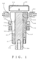
- A method for producing a metal part having internal threads, comprising the steps of:inserting a second core bar axially into the center of a first core bar which is axially divided into a multiple number and has a male thread section on its outer periphery;putting a metal cylinder on the male thread section of the first core bar;applying a pressure by a plurality of punches to the outer periphery of the metal cylinder in a centripetal direction to deform the metal cylinder to transfer the male thread section of the first core bar to the inner wall of the metal cylinder to form a female thread section;removing the second core bar which has been axially inserted into the center of the first core bar from the male thread section; andcontracting the diameter of the male thread section of the first core bar in a centripetal direction to enable the removal of the metal cylinder having the female thread section formed therein without twisting.
- A method for producing a metal part having internal threads according to claim 1, wherein when the female threads are formed, the second core bar is tightly adhered axially to the inner wall of the first core bar, the first core bar is served as a rigid body to form the female threads, and the second core bar is removed from the male thread section, the diameter of the male thread section of the first core bar is contracted in the centripetal direction to make a thread ridge diameter of the male thread section of the first core bar smaller than that of the formed female threads.
- A machine for producing a metal part having internal threads, comprising:a first core bar which is axially divided into a multiple number and has a male thread section formed on its outer periphery;a second core bar which is axially inserted into the center of the first core bar;a plurality of punches which are provided around the male threshold section of the first core bar; anda pressing tool which is provided on the outer periphery of the first core bar and contracts the diameter of the male thread section of the first core bar in a centripetal direction.
- A machine for producing a metal part having internal threads according to claim 3, wherein the first core bar has a base having a through hole, and a male thread core bar member which is interconnected with the base, formed via slits which are disposed parallel to an axis and equal in a radial direction and has a male thread section formed on the outer periphery of its leading end.
- A machine for producing a metal part having internal threads according to claim 4, wherein each male thread core bar member has a male thread section, a sloped section and an elastic deformable section for contracting the male thread section.
- A machine for producing a metal part having internal threads according to any one of claim 3 through claim 5, wherein the pressing tool is made of a ring-shaped member having a sloped inner wall corresponding to the sloped section of the male thread core bar member of the first core bar.
Applications Claiming Priority (2)
| Application Number | Priority Date | Filing Date | Title |
|---|---|---|---|
| JP258898/96 | 1996-09-30 | ||
| JP8258898A JPH1099931A (en) | 1996-09-30 | 1996-09-30 | Manufacture of metallic parts having internal screw, and its device |
Publications (1)
| Publication Number | Publication Date |
|---|---|
| EP0832703A1 true EP0832703A1 (en) | 1998-04-01 |
Family
ID=17326572
Family Applications (1)
| Application Number | Title | Priority Date | Filing Date |
|---|---|---|---|
| EP97106383A Ceased EP0832703A1 (en) | 1996-09-30 | 1997-04-17 | Method for producing a metal part having internal threads and machine therefor |
Country Status (6)
| Country | Link |
|---|---|
| EP (1) | EP0832703A1 (en) |
| JP (1) | JPH1099931A (en) |
| KR (1) | KR19980024022A (en) |
| AU (1) | AU3933297A (en) |
| CA (1) | CA2203983A1 (en) |
| TW (1) | TW325509B (en) |
Cited By (2)
| Publication number | Priority date | Publication date | Assignee | Title |
|---|---|---|---|---|
| DE102008063690A1 (en) * | 2008-12-19 | 2010-07-08 | Ifm Electronic Gmbh | Method for manufacturing thread of sleeve, involves providing irregular form of sleeve with section projected radially outward in outer periphery before or during manufacturing of thread |
| DE102014017808B3 (en) * | 2014-12-03 | 2016-02-25 | Audi Ag | Apparatus and method for chipless internal thread forming |
Families Citing this family (2)
| Publication number | Priority date | Publication date | Assignee | Title |
|---|---|---|---|---|
| CN102814616B (en) * | 2012-08-30 | 2015-11-18 | 无锡迈鑫科技实业有限公司 | Thread form rectifier |
| CN112893721B (en) * | 2021-01-15 | 2022-03-22 | 西安交通大学 | Differential type planetary roller screw nut split die roll forming device and process |
Citations (3)
| Publication number | Priority date | Publication date | Assignee | Title |
|---|---|---|---|---|
| NL7901892A (en) * | 1979-03-08 | 1980-09-10 | Erico Europa | Forming self locking screw thread in tube - by cold forging on hollow former, unscrewing it after reducing temp. or internal pressure |
| DE3200755A1 (en) * | 1982-01-13 | 1984-04-26 | Helmut 2420 Eutin Krueger-Beuster | Expanding thread former |
| WO1993009896A1 (en) * | 1991-11-19 | 1993-05-27 | Fraunhofer-Gesellschaft zur Förderung der angewandten Forschung e.V. | Non-cutting tool for producing inner and outer profiles |
-
1996
- 1996-09-30 JP JP8258898A patent/JPH1099931A/en active Pending
-
1997
- 1997-04-16 TW TW086104927A patent/TW325509B/en active
- 1997-04-17 EP EP97106383A patent/EP0832703A1/en not_active Ceased
- 1997-04-29 CA CA002203983A patent/CA2203983A1/en not_active Abandoned
- 1997-05-15 KR KR1019970018735A patent/KR19980024022A/en not_active Application Discontinuation
- 1997-09-30 AU AU39332/97A patent/AU3933297A/en not_active Abandoned
Patent Citations (3)
| Publication number | Priority date | Publication date | Assignee | Title |
|---|---|---|---|---|
| NL7901892A (en) * | 1979-03-08 | 1980-09-10 | Erico Europa | Forming self locking screw thread in tube - by cold forging on hollow former, unscrewing it after reducing temp. or internal pressure |
| DE3200755A1 (en) * | 1982-01-13 | 1984-04-26 | Helmut 2420 Eutin Krueger-Beuster | Expanding thread former |
| WO1993009896A1 (en) * | 1991-11-19 | 1993-05-27 | Fraunhofer-Gesellschaft zur Förderung der angewandten Forschung e.V. | Non-cutting tool for producing inner and outer profiles |
Cited By (2)
| Publication number | Priority date | Publication date | Assignee | Title |
|---|---|---|---|---|
| DE102008063690A1 (en) * | 2008-12-19 | 2010-07-08 | Ifm Electronic Gmbh | Method for manufacturing thread of sleeve, involves providing irregular form of sleeve with section projected radially outward in outer periphery before or during manufacturing of thread |
| DE102014017808B3 (en) * | 2014-12-03 | 2016-02-25 | Audi Ag | Apparatus and method for chipless internal thread forming |
Also Published As
| Publication number | Publication date |
|---|---|
| KR19980024022A (en) | 1998-07-06 |
| AU3933297A (en) | 1998-04-02 |
| JPH1099931A (en) | 1998-04-21 |
| TW325509B (en) | 1998-01-21 |
| CA2203983A1 (en) | 1998-03-30 |
Similar Documents
| Publication | Publication Date | Title |
|---|---|---|
| EP0304070B1 (en) | Improved swaged collar fastener | |
| CA2118732C (en) | Method of manufacturing tee nut | |
| EP0453167A1 (en) | Method of manufacturing outside ring | |
| EP0832703A1 (en) | Method for producing a metal part having internal threads and machine therefor | |
| US4450704A (en) | Metal sleeve production | |
| EP0486889A2 (en) | Reset device for microprocessor, particularly for automotive applications | |
| US6935482B2 (en) | Clutch gear having boss part with spline and method for manufacturing the same | |
| US5938380A (en) | Method for rotationally driving gear material when hob machining is performed, and gear | |
| US7047787B2 (en) | Method of forming spline and keyway for sheet metal rotating member with boss part | |
| JPH0569616B2 (en) | ||
| JPH102342A (en) | Yoke for shaft coupling and manufacture of shaft coupling yoke | |
| JPH0929362A (en) | Device and method for forming connecting end of pipe | |
| JPH04356324A (en) | Method and device for forging spline shaft | |
| KR100680896B1 (en) | Hose coupling, intermediate blank material for making the same, and hose assembly using same | |
| JP4609778B2 (en) | Insert metal fitting and manufacturing method thereof | |
| JP2000140984A (en) | Method and device for production of inner wheel for constant velocity joint | |
| CN110369750A (en) | A kind of thin-walled brass cam path machining special fixture | |
| JPH0688097B2 (en) | Ball stud manufacturing method | |
| JPH0579420B2 (en) | ||
| JP2620346B2 (en) | Transmission gear tooth forming method | |
| US20020104433A1 (en) | Fluid-actuated cylinder and method for manufacturing it | |
| JP2001246441A (en) | Manufacturing method of spline piece gear | |
| JP3768652B2 (en) | Engine valve cold forging method | |
| JP2774266B2 (en) | Method of manufacturing a groove in a journal, shaft end or fixed shaft end of a workpiece | |
| JPS5853225B2 (en) | Crimp joining method between sleeve and steel wire |
Legal Events
| Date | Code | Title | Description |
|---|---|---|---|
| PUAI | Public reference made under article 153(3) epc to a published international application that has entered the european phase |
Free format text: ORIGINAL CODE: 0009012 |
|
| AK | Designated contracting states |
Kind code of ref document: A1 Designated state(s): DE FR GB IT SE |
|
| 17P | Request for examination filed |
Effective date: 19980915 |
|
| AKX | Designation fees paid |
Free format text: DE FR GB IT SE |
|
| RBV | Designated contracting states (corrected) |
Designated state(s): DE FR GB IT SE |
|
| RTI1 | Title (correction) |
Free format text: METHOD FOR PRODUCING A METAL PART HAVING INTERNAL THREADS AND DEVICE THEREFORE |
|
| GRAG | Despatch of communication of intention to grant |
Free format text: ORIGINAL CODE: EPIDOS AGRA |
|
| RTI1 | Title (correction) |
Free format text: METHOD FOR PRODUCING A METAL PART HAVING INTERNAL THREADS AND DEVICE THEREFORE |
|
| 17Q | First examination report despatched |
Effective date: 20000119 |
|
| STAA | Information on the status of an ep patent application or granted ep patent |
Free format text: STATUS: THE APPLICATION HAS BEEN REFUSED |
|
| 18R | Application refused |
Effective date: 20000714 |