EP0831969B1 - Vorrichtung und verfahren zum herstellen eines wabenkörpers, insbesondere eines katalysator-trägerkörpers - Google Patents
Vorrichtung und verfahren zum herstellen eines wabenkörpers, insbesondere eines katalysator-trägerkörpers Download PDFInfo
- Publication number
- EP0831969B1 EP0831969B1 EP96919776A EP96919776A EP0831969B1 EP 0831969 B1 EP0831969 B1 EP 0831969B1 EP 96919776 A EP96919776 A EP 96919776A EP 96919776 A EP96919776 A EP 96919776A EP 0831969 B1 EP0831969 B1 EP 0831969B1
- Authority
- EP
- European Patent Office
- Prior art keywords
- stack
- honeycomb body
- pivoting
- stacks
- central axis
- Prior art date
- Legal status (The legal status is an assumption and is not a legal conclusion. Google has not performed a legal analysis and makes no representation as to the accuracy of the status listed.)
- Expired - Lifetime
Links
- 238000000034 method Methods 0.000 title claims description 25
- 239000012530 fluid Substances 0.000 claims abstract description 11
- 239000002184 metal Substances 0.000 claims abstract description 11
- 238000004519 manufacturing process Methods 0.000 claims description 12
- 238000011161 development Methods 0.000 claims description 8
- 238000005452 bending Methods 0.000 claims description 3
- 230000006835 compression Effects 0.000 claims description 2
- 238000007906 compression Methods 0.000 claims description 2
- 238000004804 winding Methods 0.000 claims description 2
- 238000007493 shaping process Methods 0.000 claims 12
- 230000000717 retained effect Effects 0.000 claims 2
- 241000397426 Centroberyx lineatus Species 0.000 claims 1
- 230000003197 catalytic effect Effects 0.000 claims 1
- 239000003054 catalyst Substances 0.000 description 8
- 230000018109 developmental process Effects 0.000 description 7
- 230000006978 adaptation Effects 0.000 description 1
- 238000010276 construction Methods 0.000 description 1
- 238000006073 displacement reaction Methods 0.000 description 1
- 230000002996 emotional effect Effects 0.000 description 1
- 239000003344 environmental pollutant Substances 0.000 description 1
- 210000003746 feather Anatomy 0.000 description 1
- 239000003863 metallic catalyst Substances 0.000 description 1
- 231100000719 pollutant Toxicity 0.000 description 1
- 239000007858 starting material Substances 0.000 description 1
Images


Classifications
-
- B01J35/56—
-
- F—MECHANICAL ENGINEERING; LIGHTING; HEATING; WEAPONS; BLASTING
- F01—MACHINES OR ENGINES IN GENERAL; ENGINE PLANTS IN GENERAL; STEAM ENGINES
- F01N—GAS-FLOW SILENCERS OR EXHAUST APPARATUS FOR MACHINES OR ENGINES IN GENERAL; GAS-FLOW SILENCERS OR EXHAUST APPARATUS FOR INTERNAL COMBUSTION ENGINES
- F01N3/00—Exhaust or silencing apparatus having means for purifying, rendering innocuous, or otherwise treating exhaust
- F01N3/08—Exhaust or silencing apparatus having means for purifying, rendering innocuous, or otherwise treating exhaust for rendering innocuous
- F01N3/10—Exhaust or silencing apparatus having means for purifying, rendering innocuous, or otherwise treating exhaust for rendering innocuous by thermal or catalytic conversion of noxious components of exhaust
- F01N3/24—Exhaust or silencing apparatus having means for purifying, rendering innocuous, or otherwise treating exhaust for rendering innocuous by thermal or catalytic conversion of noxious components of exhaust characterised by constructional aspects of converting apparatus
- F01N3/28—Construction of catalytic reactors
- F01N3/2803—Construction of catalytic reactors characterised by structure, by material or by manufacturing of catalyst support
- F01N3/2807—Metal other than sintered metal
- F01N3/281—Metallic honeycomb monoliths made of stacked or rolled sheets, foils or plates
-
- B—PERFORMING OPERATIONS; TRANSPORTING
- B21—MECHANICAL METAL-WORKING WITHOUT ESSENTIALLY REMOVING MATERIAL; PUNCHING METAL
- B21D—WORKING OR PROCESSING OF SHEET METAL OR METAL TUBES, RODS OR PROFILES WITHOUT ESSENTIALLY REMOVING MATERIAL; PUNCHING METAL
- B21D53/00—Making other particular articles
- B21D53/02—Making other particular articles heat exchangers or parts thereof, e.g. radiators, condensers fins, headers
- B21D53/027—Making other particular articles heat exchangers or parts thereof, e.g. radiators, condensers fins, headers by helically or spirally winding elongated elements
-
- F—MECHANICAL ENGINEERING; LIGHTING; HEATING; WEAPONS; BLASTING
- F01—MACHINES OR ENGINES IN GENERAL; ENGINE PLANTS IN GENERAL; STEAM ENGINES
- F01N—GAS-FLOW SILENCERS OR EXHAUST APPARATUS FOR MACHINES OR ENGINES IN GENERAL; GAS-FLOW SILENCERS OR EXHAUST APPARATUS FOR INTERNAL COMBUSTION ENGINES
- F01N3/00—Exhaust or silencing apparatus having means for purifying, rendering innocuous, or otherwise treating exhaust
- F01N3/08—Exhaust or silencing apparatus having means for purifying, rendering innocuous, or otherwise treating exhaust for rendering innocuous
- F01N3/10—Exhaust or silencing apparatus having means for purifying, rendering innocuous, or otherwise treating exhaust for rendering innocuous by thermal or catalytic conversion of noxious components of exhaust
- F01N3/24—Exhaust or silencing apparatus having means for purifying, rendering innocuous, or otherwise treating exhaust for rendering innocuous by thermal or catalytic conversion of noxious components of exhaust characterised by constructional aspects of converting apparatus
- F01N3/28—Construction of catalytic reactors
-
- F—MECHANICAL ENGINEERING; LIGHTING; HEATING; WEAPONS; BLASTING
- F01—MACHINES OR ENGINES IN GENERAL; ENGINE PLANTS IN GENERAL; STEAM ENGINES
- F01N—GAS-FLOW SILENCERS OR EXHAUST APPARATUS FOR MACHINES OR ENGINES IN GENERAL; GAS-FLOW SILENCERS OR EXHAUST APPARATUS FOR INTERNAL COMBUSTION ENGINES
- F01N2330/00—Structure of catalyst support or particle filter
- F01N2330/02—Metallic plates or honeycombs, e.g. superposed or rolled-up corrugated or otherwise deformed sheet metal
- F01N2330/04—Methods of manufacturing
Definitions
- the present invention relates to an apparatus and a method for producing a honeycomb body with a variety of for one Fluid-permeable channels, in particular a catalyst carrier body.
- honeycomb bodies To avoid pollutants, especially in motor vehicle exhaust catalyst carrier bodies are used. With such catalyst carrier bodies it can be metallic honeycomb bodies.
- the honeycomb body comprises a stack of a plurality of at least partially structured Sheets. The stack is opposite to itself and one Central area devoured.
- Such a design of a honeycomb body is e.g. B. is known by the patent US 4 923 109.
- WO 90/03220 is a metallic catalyst carrier body for Motor vehicles known, made of at least partially structured sheets is constructed.
- This catalyst carrier body comprises at least three stacks of sheets, with at least three of the stacks being associated with one each Folded line folded in the central area of the honeycomb body and in the folded Condition in the same direction around each other and around the central area with the crease lines are devoured.
- the one fork-shaped, rotatable about an axis and engaging on each stack Wrapping device and form segments closing into a form includes.
- the inner contour of the closed form corresponds to the Outer contour of the honeycomb body in the wrapped state.
- the most frequent The shape in which the honeycomb bodies are formed is cylindrical.
- the mold segments are moved towards the stack that during the rotation of the fork-shaped entangling device of the stacks or the stacks lie against the edge of the mold segments and this edge Abutment forms.
- the shape completely closed giving the honeycomb its final shape awarded.
- the known devices have two shape segments that are straight are movable towards and away from each other. During the closing process there is a risk that at least one mold segment against the Direction of movement of the section of a stack still to be devoured emotional. If the shape segment comes against the section, it can become a undesirable deformation of the stack or the stack. The Deformation leads to individual sheets being partially bent. This affects the structure of the finished honeycomb body. On the one hand the strength of the honeycomb body suffers and on the other hand there is a local change in the channel cross-sections.
- the present invention is based on the object to further develop the known device for producing a honeycomb body, that during the manufacturing process there is a risk of deformation of Stacking or individual sheets does not occur. Furthermore, a method for Production of a honeycomb body can be specified, through which a Deformation of individual stacks is avoided.
- this object is achieved by a device with the features solved according to claim 1.
- Advantageous further developments of the device are the subject of subclaims 2 to 18 according to the invention
- Processes for producing a honeycomb body are in claims 19 and 20 included.
- An advantageous further development of the method is the subject of subclaim 21.
- the device according to the invention for producing a honeycomb body at least one stack of a plurality of at least partially structured Sheet metal, which has a plurality of channels permeable to a fluid form has a shape that has at least two shape segments.
- Each shape segment is about a pivot axis, respectively runs parallel to the axis of the belt device, against the direction of rotation the looping device can be pivoted.
- the device has more as two stacks, a number of corresponding to the number of stacks Form segments on which counter to the direction of rotation of the belt are pivotable.
- the pivot axes of the mold segments are preferred equidistant from each other on a covering the finished honeycomb body arranged.
- the sheets of the stack of a honeycomb body become strong claimed.
- the stress on the metal sheets results, among other things from the fact that the abutment is arranged at a distance from the force introduction center is.
- the system abutment, sheet stack and force introduction center is comparable to a layered leaf spring clamped on one side. How even with such a layered leaf spring, occur between the individual There was friction on a stack. This friction is caused by winding an increased use of energy.
- the not yet embraced Section of each stack bent, causing flexing of the Stack is conditional.
- the devices and advantageous developments of the method go from the basic idea that the manufacturability of a honeycomb body with a plurality of channels permeable to a fluid, in particular a catalyst carrier body, is cheaper if the abutment immediately abuts on the wrapped stack or stacks. Of the not yet wrapped section of each stack is free. Arise therefore, as is the case with the prior art, no stresses of the not yet wrapped section of the stack. It is coming therefore not to a bending stress of the not yet wrapped Section of the stack.
- a device for Manufacture a honeycomb body with a variety of fluid permeable Channels in particular a catalyst that a stack from a Includes a plurality of at least partially structured sheets, which around a an axially rotatable fork-shaped belt device engaging the stack and has a form-fitting mold segments, wherein the pivot axis at an end of each forming an abutment Form segment is arranged, and each abutment to the axis and from this is displaceable, realized.
- this device it is Abutment always on the stack while looping.
- the radial extension increases during the wrapping process of the already wrapped stack. To invoice this process wear, the abutment to the axis of the belt and back movable away from this.
- the abutment can with a definite pressure rest on the stack.
- a device is proposed where the number of shape segments is the shape of the number of stacks corresponds.
- Each shape segment is about a pivot axis, each parallel runs to the axis, and at an end forming an abutment arranged.
- the shape segments are against the direction of rotation of the belt device pivotable.
- Each abutment is to the axis of the belt device Slidable to and from this.
- a further development of the Device proposed that a base plate with itself radially to the center extending guide grooves. There is one in each guide groove Swivel axis forming bolt slidably guided. Each guide groove faces a polygonal cross section.
- An embodiment of the Guide groove that has a T-shaped or dovetail cross-section having.
- the bolt has a corresponding head, which engages in the guide groove. It is not imperative that the guide grooves are formed in a one-piece base plate.
- the guide grooves can also be constructed from several appropriately designed panels.
- the movement of the abutments towards and away from the axis takes place preferably by electric motor.
- a stepper motor is used for this Suitable, as this allows the displacement of the Abutment from the already wrapped stack is achieved.
- Between the electromotive drive and the abutment can also be a corresponding one Gear can be provided.
- each Abutment is connected to a piston-cylinder unit.
- the piston-cylinder unit can be operated hydraulically or pneumatically.
- piston-cylinder units can be operated hydraulically or pneumatically.
- the pivot axes away from the central axis against one To move spring force can be by means of a pull or a compression spring or pairs of such springs are generated.
- the spring force with which the re-bearing on the intertwined Stack rests adjustable. This allows an adaptation of the device to the shape and the starting materials of the honeycomb body.
- the spring force preferably has a degressive profile. The is based on the consideration that the force with which the re-stock applies the stack rests, may be smaller due to the larger bending radius than at the core of the curved stack.
- the use of feathers also has the advantage that these are standardized components that work safely and reliably.
- Each mold segment is equipped with a drive unit to close the mold connected which a corresponding shape segment around the respective Swivel axis swiveled.
- This drive unit can be a act hydraulically or pneumatically operated piston-cylinder unit.
- the process is a stack of sheet metal from a plurality of at least partially structured sheet metal layered.
- This stack is in an open form brought in. In a central area of the stack and shape, the Stack held by a belt.
- the belt device can be fork-shaped.
- the stack is made by the Loop wrapped around. By swiveling the mold segments the form becomes against the direction of rotation of the belt closed. The form can be closed if a given Degree of wrap is reached. It is not imperative that the stack is completely entwined.
- the mold closing process can already be initiated when the extension of the not yet wrapped Section of the stack is less than or equal to the length in Circumferential direction of the mold segment. Then the closing process already initiated, each segment supports the wrapping process, because the closing segments the not yet wrapped sections Push the axis towards.
- EP 0 245 737 known honeycomb body manufactured. Such a honeycomb body is in the Experts known as S-Kat.
- WO 89/03220 proposed a plurality of stacks of a plurality of at least to layer partially structured sheets. Each stack is increased by one Folded line folded. Each stack is placed in an open form, and in this by a belt device in a central area of the Kept in shape.
- the wrapping device grabbed the stack has an abutment on both sides of the stack in the central area to be arranged, which are positioned opposite one another, for contact with the stack brought. Then the stack is wrapped in opposite directions. Each abutment moves radially during the wrapping process out of the central area, with the abutments always on the stack issue. When the surrounding process is finished, the shape segments become pivoted about their respective pivot axis, whereby the mold is closed becomes.
- the device comprises a shape 5, which consists of two mold segments 6, 7. Each shape segment 6, 7 is pivotable about a respective pivot axis 13, 14. The ends of each Form segments 6, 7 is designed so that the closed form one forms almost continuous lines.
- the honeycomb body 31 has a circular cross section on. The two shape segments 6, 7 are diametrically on the envelope 32 educated.
- the stack 1 is introduced into the open mold 5 and there by one Belt means not shown held.
- the belt device is fork-shaped and one perpendicular to the Axis 9 in the drawing plane is rotatable.
- the direction of rotation of the belt device about axis 9 is denoted by S.
- S The direction of rotation of the belt device about axis 9
- Fig. 2 is it can be seen that the stack 1 is partially intertwined.
- Not yet wrapped part of the stack 1 has a length L, which the half circumference of the envelope 32 corresponds.
- the shape segments 6, 7 in the arrow directions F to the respective Pivot axes 13, 14 are pivoted so as to close the mold 5.
- the shape segments 6, 7 press the not yet wrapped Section of the stack 1 to the core of the stack.
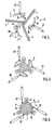
- Form 4 to 6 is a second embodiment of a device to make a honeycomb body from three stacks 1, 2 and 3.
- the stacks 1, 2 and 3 are arranged symmetrically about the axis 9.
- a belt device, which holds each stack 1, 2 and 3 and in Direction of rotation S rotated, is not shown for better clarity.
- the wrapping device can act as a fork.
- Form 5 comprises three Shape segments 6, 7 and 8.
- Each shape segment 6, 7 and 8 is circular sector-shaped educated.
- Each shape segment 6, 7 and 8 is each one Axes 13, 14 and 15 against the direction of rotation S of the belt device pivotable.
- a drive unit 25, 26, 27 is provided in each case. With the drive units 25, 26 and 27 are each piston-cylinder units.
- the piston rod 28, 29, 30 are with the shaped segment 6, 7 or 8 connected.
- the connection is designed to be pivotable. Every drive unit 25, 26, 27 is arranged in a stationary manner.
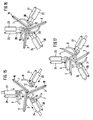
- the device for Manufacture of a honeycomb body from a stack 1 has two shaped segments 6, 7, which are each pivotable about the pivot axes 13, 14. Each segment 6, 7 is radial to the axis 9 of a belt device movable. 7 is the arrangement of a stack in the open Form 5 shown. After the stack is placed in the mold and was seized by a belt device, not shown, are the shape segments 6, 7 radially inward in the direction of arrows R. Move to stack 1. Each mold segment 6, 7 comes to rest with one end. At this end is the pivot axis 13 or 14 trained. The end of the mold segment that is on the stack 1 is present, forms an abutment 10, 11.
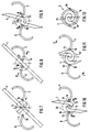
- the device comprises three folding units 19, 20 and 21.
- Each Folding unit 19, 20, 21 has a folding mandrel 33, 34 and 35.
- the folding mandrel 33, 34 and 35 is movable back and forth along a straight line.
- Each folding unit 19, 20, 21 has a two-part lock 36, 37 and 38 on.
- Locks 36, 37 and 38 each have two around axes 39, 40 pivotable gates 41, 42. The pivotability takes place against a force.
- the stack becomes parallel arranged to lock 36, 37 and 38 respectively.
- Symmetrical between the lock gates 41, 42 the mandrel 33 is arranged.
- the stack 1 is folded around the fold line 16.
- the folded state is shown in FIG. 14.
- the stacks 1, 2 and 3 inserted into the central area 4 of the device.
- the stacks 1, 2 and 3 are arranged symmetrically with respect to the axis 9. After this The folds 33, 34, 35 are made from the respective stack pulled out.
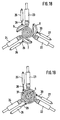
- Figures 15 to 19 are the buckling devices 19, 20 and 21 no longer shown for clarity.
- a looping device not shown, has each stack 1, 2 and 3 seized.
- the individual shape segments 6, 7 and 8 are by means of a cylinder-piston unit 22, 23 and 24 radially inward to the axis 9 postponed.
- the shifting process continues until the on a End of each mold segment 6, 7 and 8 formed abutment 10, 11th and 12 lie against the relevant stack 1, 2 and 3, as in the Fig. 16 is shown. If the abutments lie on stacks 1, 2 and 3, so the wrapping process can be initiated.
- a state of Wrapping of the individual stacks 1, 2 and 3 is shown in FIG. 17.
- the mold segments 6, 7 and 8 are one pivot axis 13, 14 each pivotable. 18 and 19 correspond to FIGS. 5 and 6, to which full reference is made becomes.
- honeycomb bodies described in the exemplary embodiments have a circular cross section.
- honeycomb bodies are produced which are not circular Have cross-section. This can be, for. B. also honeycomb act that have an Egyptian, part circular or epitrochoidal cross section exhibit.
Applications Claiming Priority (3)
| Application Number | Priority Date | Filing Date | Title |
|---|---|---|---|
| DE19521685A DE19521685C2 (de) | 1995-06-14 | 1995-06-14 | Verfahren und Vorrichtung zum Herstellen eines Wabenkörpers |
| DE19521685 | 1995-06-14 | ||
| PCT/EP1996/002094 WO1997000135A1 (de) | 1995-06-14 | 1996-05-15 | Vorrichtung und verfahren zum herstellen eines wabenkörpers, insbesondere eines katalysator-trägerkörpers |
Publications (2)
| Publication Number | Publication Date |
|---|---|
| EP0831969A1 EP0831969A1 (de) | 1998-04-01 |
| EP0831969B1 true EP0831969B1 (de) | 1999-09-01 |
Family
ID=7764393
Family Applications (1)
| Application Number | Title | Priority Date | Filing Date |
|---|---|---|---|
| EP96919776A Expired - Lifetime EP0831969B1 (de) | 1995-06-14 | 1996-05-15 | Vorrichtung und verfahren zum herstellen eines wabenkörpers, insbesondere eines katalysator-trägerkörpers |
Country Status (14)
| Country | Link |
|---|---|
| EP (1) | EP0831969B1 (ja) |
| JP (1) | JP3853365B2 (ja) |
| KR (1) | KR100396963B1 (ja) |
| CN (1) | CN1078101C (ja) |
| AU (1) | AU5818796A (ja) |
| BR (1) | BR9608354A (ja) |
| DE (2) | DE19521685C2 (ja) |
| ES (1) | ES2137707T3 (ja) |
| IN (1) | IN191301B (ja) |
| MX (1) | MX9710014A (ja) |
| MY (1) | MY116654A (ja) |
| RU (1) | RU2154528C2 (ja) |
| TW (1) | TW327144B (ja) |
| WO (1) | WO1997000135A1 (ja) |
Cited By (2)
| Publication number | Priority date | Publication date | Assignee | Title |
|---|---|---|---|---|
| US7383633B2 (en) | 2002-06-13 | 2008-06-10 | Emitec Gesellschaft Fuer Emissionstechnologie Mbh | Non-cylindrical catalytic-converter carrier element and tool, and method for manufacturing it |
| DE102009035612A1 (de) * | 2009-07-31 | 2011-02-03 | Emitec Gesellschaft Für Emissionstechnologie Mbh | Wabenkörper und Verfahren zu seiner Herstellung |
Families Citing this family (18)
| Publication number | Priority date | Publication date | Assignee | Title |
|---|---|---|---|---|
| DE19704521A1 (de) | 1997-02-06 | 1998-08-13 | Emitec Emissionstechnologie | Verfahren und Vorrichtung zur Herstellung eines Wabenkörpers |
| GB2325424B (en) * | 1997-05-20 | 2001-01-24 | Emitec Emissionstechnologie | Production of a honeycomb body of twisted sheet layers |
| KR100517786B1 (ko) | 1997-09-03 | 2005-09-30 | 에미텍 게젤샤프트 퓌어 에미시온스테크놀로기 엠베하 | 엔진실에 장착되는 촉매 지지 장치 |
| DE19755703B4 (de) * | 1997-12-15 | 2008-03-13 | Emitec Gesellschaft Für Emissionstechnologie Mbh | Katalysatorträgeranordnung für einen motornahen Einbau |
| DE19817787C2 (de) | 1998-04-21 | 2000-04-13 | Emitec Emissionstechnologie | Verfahren und Vorrichtung zum Herstellen eines metallischen Wabenkörpers |
| DE19825018A1 (de) | 1998-06-04 | 1999-12-09 | Emitec Emissionstechnologie | Verfahren und Blechpaket zur Herstellung eines Wabenkörpers mit einer Vielzahl von für ein Fluid durchlässigen Kanälen |
| DE19912871A1 (de) | 1999-03-22 | 2000-09-28 | Emitec Emissionstechnologie | Verfahren und Vorrichtung zum Herstellen eines metallischen Wabenkörpers |
| DE10329002A1 (de) | 2003-06-27 | 2005-01-20 | Emitec Gesellschaft Für Emissionstechnologie Mbh | Aufbau einer metallischen Wabenstruktur und Verfahren zu dessen Herstellung |
| DE102005038572A1 (de) * | 2005-08-12 | 2007-02-15 | Emitec Gesellschaft Für Emissionstechnologie Mbh | Vorrichtung und Verfahren zur Herstellung metallischer Wabenkörper mit mindestens einem Formsegment |
| CN101251036B (zh) * | 2007-08-29 | 2010-06-09 | 温州市亿达环保技术有限公司 | 制作s型金属蜂窝的装置 |
| WO2013063754A1 (en) * | 2011-11-01 | 2013-05-10 | Basf Corporation | System and method for manufacturing a honeycomb body |
| CN102784852B (zh) * | 2012-02-14 | 2014-07-23 | 无锡敏功科技有限公司 | 一种s型金属蜂窝载体制作装置 |
| CN102553980A (zh) * | 2012-02-24 | 2012-07-11 | 丁胜康 | 一种双s蜂窝状金属载体的卷制装置 |
| CN102699164A (zh) * | 2012-05-16 | 2012-10-03 | 丁胜康 | 一种金属蜂窝载体卷制装置 |
| CN102728677B (zh) * | 2012-06-19 | 2016-04-13 | 台州欧信环保净化器有限公司 | 一种s型金属蜂窝载体的制作装置 |
| CN104826903B (zh) * | 2015-05-11 | 2016-03-23 | 季金菊 | 双s型蜂窝载体的成型方法及其成型装置 |
| DE102016210235A1 (de) * | 2016-06-09 | 2017-12-28 | Continental Automotive Gmbh | Verfahren zur Herstellung einer Wabenstruktur |
| CN109019149B (zh) * | 2018-06-13 | 2020-05-15 | 北京安达泰克科技有限公司 | 金属蜂窝载体的缠绕设备 |
Family Cites Families (9)
| Publication number | Priority date | Publication date | Assignee | Title |
|---|---|---|---|---|
| ATE45781T1 (de) * | 1986-05-12 | 1989-09-15 | Interatom | Wabenkoerper, insbesondere katalysatortr|gerk¯rper, mit gegensinnig verschlungenen metallblechschichten und verfahren zu seiner herstellung. |
| DE3743724A1 (de) * | 1987-12-23 | 1989-07-13 | Hoerauf Maschinenfabrik Gmbh & | Briefordnerdeckel |
| DE3743723C1 (de) * | 1987-12-23 | 1989-04-20 | Sueddeutsche Kuehler Behr | Verfahren und Vorrichtung zur Herstellung eines Traegerkoerpers fuer einen katalytischen Reaktor |
| KR960012698B1 (ko) * | 1988-09-22 | 1996-09-24 | 에미텍 게젤샤프트 퓌어 에미시온스테크놀로기 엠베하 | 다수의 금속판재로 이루어진 벌집형 구조물 및 그 제조방법 |
| CN1021023C (zh) * | 1988-09-22 | 1993-06-02 | 埃米特放射技术股份有限公司 | 由数个包绕叠板件制成的蜂窝体,特别适用于催化载体 |
| CA2083742A1 (en) * | 1992-02-19 | 1993-08-20 | David T. Sheller | Core element for catalytic converter |
| JPH0639294A (ja) * | 1992-05-04 | 1994-02-15 | W R Grace & Co | 触媒式コンバーターのためのコア要素 |
| DE4221763A1 (de) * | 1992-07-02 | 1994-01-05 | Schwaebische Huettenwerke Gmbh | Verfahren zum Herstellen eines Katalysators |
| ES2086948T3 (es) * | 1992-07-14 | 1996-07-01 | Emitec Emissionstechnologie | Cuerpo alveolar metalico compuesto de capas de chapa entrelazadas, y procedimiento para su fabricacion. |
-
1995
- 1995-06-14 DE DE19521685A patent/DE19521685C2/de not_active Expired - Fee Related
-
1996
- 1996-05-06 IN IN828CA1996 patent/IN191301B/en unknown
- 1996-05-09 TW TW085105507A patent/TW327144B/zh not_active IP Right Cessation
- 1996-05-15 BR BR9608354A patent/BR9608354A/pt not_active IP Right Cessation
- 1996-05-15 RU RU98101118/12A patent/RU2154528C2/ru not_active IP Right Cessation
- 1996-05-15 JP JP50254297A patent/JP3853365B2/ja not_active Expired - Lifetime
- 1996-05-15 AU AU58187/96A patent/AU5818796A/en not_active Abandoned
- 1996-05-15 KR KR1019970709323A patent/KR100396963B1/ko not_active IP Right Cessation
- 1996-05-15 WO PCT/EP1996/002094 patent/WO1997000135A1/de active IP Right Grant
- 1996-05-15 DE DE59602954T patent/DE59602954D1/de not_active Expired - Lifetime
- 1996-05-15 CN CN96194765A patent/CN1078101C/zh not_active Expired - Fee Related
- 1996-05-15 ES ES96919776T patent/ES2137707T3/es not_active Expired - Lifetime
- 1996-05-15 EP EP96919776A patent/EP0831969B1/de not_active Expired - Lifetime
- 1996-06-12 MY MYPI96002361A patent/MY116654A/en unknown
-
1997
- 1997-12-10 MX MX9710014A patent/MX9710014A/es unknown
Cited By (3)
| Publication number | Priority date | Publication date | Assignee | Title |
|---|---|---|---|---|
| US7383633B2 (en) | 2002-06-13 | 2008-06-10 | Emitec Gesellschaft Fuer Emissionstechnologie Mbh | Non-cylindrical catalytic-converter carrier element and tool, and method for manufacturing it |
| US8389438B2 (en) | 2002-06-13 | 2013-03-05 | Emitec Gesellschaft Fuer Emissionstechnologie Mbh | Non-cylindrical catalytic-converter carrier element and tool, and method for manufacturing it |
| DE102009035612A1 (de) * | 2009-07-31 | 2011-02-03 | Emitec Gesellschaft Für Emissionstechnologie Mbh | Wabenkörper und Verfahren zu seiner Herstellung |
Also Published As
| Publication number | Publication date |
|---|---|
| MX9710014A (es) | 1998-07-31 |
| JPH11508814A (ja) | 1999-08-03 |
| CN1078101C (zh) | 2002-01-23 |
| WO1997000135A1 (de) | 1997-01-03 |
| AU5818796A (en) | 1997-01-15 |
| DE19521685C2 (de) | 1998-04-16 |
| ES2137707T3 (es) | 1999-12-16 |
| CN1187784A (zh) | 1998-07-15 |
| RU2154528C2 (ru) | 2000-08-20 |
| MY116654A (en) | 2004-03-31 |
| TW327144B (en) | 1998-02-21 |
| IN191301B (ja) | 2003-11-15 |
| JP3853365B2 (ja) | 2006-12-06 |
| DE59602954D1 (de) | 1999-10-07 |
| KR19990022854A (ko) | 1999-03-25 |
| BR9608354A (pt) | 1998-07-28 |
| DE19521685A1 (de) | 1996-12-19 |
| EP0831969A1 (de) | 1998-04-01 |
| KR100396963B1 (ko) | 2003-10-17 |
Similar Documents
| Publication | Publication Date | Title |
|---|---|---|
| EP0831969B1 (de) | Vorrichtung und verfahren zum herstellen eines wabenkörpers, insbesondere eines katalysator-trägerkörpers | |
| EP0639363B1 (de) | Tampon sowie Verfahren und Vorrichtung zu seiner Herstellung | |
| DE2633039C3 (de) | Aus einem becherförmigen Blechteil geformte Keilriemenscheibe und Verfahren zu deren Herstellung | |
| EP1912752B1 (de) | Vorrichtung und verfahren zur herstellung metallischer wabenkörper mit mindestens einem formsegment | |
| DE2820828C3 (de) | Verfahren zur Herstellung von Wulstkernen für Luftreifen | |
| DE2700327C2 (de) | Verfahren und Vorrichtung zum Herstellen eines Reifens mit geschlossener Torusform | |
| EP0833691B1 (de) | Vorrichtung und verfahren zum herstellen eines wabenkörpers aus verschlungenen blechlagen | |
| EP0846219B1 (de) | Vorrichtung und verfahren zur herstellung eines wabenkörpers | |
| DE102008057463A1 (de) | Feder aus einem Faserverbundwerkstoff sowie Verfahren und Vorrichtung zur Herstellung derselben | |
| EP0958053B1 (de) | Verfahren und vorrichtung zur herstellung eines wabenkörpers | |
| DE102008025590A1 (de) | Vorrichtung und Verfahren zum Wickeln eines Flachdrahtes | |
| DE4117955A1 (de) | Vorrichtung zum biegen von buegeln aus betonstahl | |
| DE4032424C2 (de) | Verfahren und Vorrichtung zur Herstellung von gefalzten Rohren | |
| EP1157198B1 (de) | Katalysatoranordnung mit katalysator-trägerkörpern und vorrichtung sowie verfahren zu deren herstellung | |
| DE1514952A1 (de) | Lamellen-Magnetkern fuer induktive Geraete,insbesondere Transformatoren,sowie Verfahren zu seiner Herstellung | |
| DE2801107C3 (de) | Verfahren und Vorrichtung zur Herstellung von zylindrischen Schraubenfedern aus Draht | |
| WO1999020414A1 (de) | Verfahren zur herstellung einer welle aus einem rohrstück, vorrichtung zur herstellung einer welle aus einem rohrstück und aus einem rohrstück hergestellte nockenwelle | |
| DE2605007C3 (de) | Pressbindemaschine | |
| DE2237423A1 (de) | Rohrbaugruppe und verfahren und einrichtung zu ihrer herstellung | |
| DE19908076C2 (de) | Verfahren und Einrichtung zum Abbinden von Spaltbandbunden | |
| DE3943368C2 (de) | Vorrichtung zum Herstellen eines Faltenbalg- oder Wellrohrs | |
| EP0128570A2 (de) | Verfahren und Vorrichtung zur Herstellung von aus Metallprofilen bestehenden Rundkörpern, insbesondere von Radfelgen für Kraftfahrzeuge | |
| DE102013224396A1 (de) | Rundbiegevorrichtung und Verfahren zum Umformen von Bandabschnitten zu Rundkörpern, insbesondere Hülsen, durch Biegen um die Umfangsfläche eines runden Biegekerns | |
| DE2340138C2 (de) | Verfahren und Vorrichtung zum Herstellen von Wellengittern aus Endlosdraht für Gitterträger | |
| EP2165785A1 (de) | Vorrichtung und Verfahren zur Herstellung von Längsnuten in zylindrischen Werkstücken |
Legal Events
| Date | Code | Title | Description |
|---|---|---|---|
| PUAI | Public reference made under article 153(3) epc to a published international application that has entered the european phase |
Free format text: ORIGINAL CODE: 0009012 |
|
| 17P | Request for examination filed |
Effective date: 19971103 |
|
| AK | Designated contracting states |
Kind code of ref document: A1 Designated state(s): DE ES FR GB IT |
|
| 17Q | First examination report despatched |
Effective date: 19980519 |
|
| GRAG | Despatch of communication of intention to grant |
Free format text: ORIGINAL CODE: EPIDOS AGRA |
|
| GRAG | Despatch of communication of intention to grant |
Free format text: ORIGINAL CODE: EPIDOS AGRA |
|
| GRAH | Despatch of communication of intention to grant a patent |
Free format text: ORIGINAL CODE: EPIDOS IGRA |
|
| GRAH | Despatch of communication of intention to grant a patent |
Free format text: ORIGINAL CODE: EPIDOS IGRA |
|
| GRAA | (expected) grant |
Free format text: ORIGINAL CODE: 0009210 |
|
| AK | Designated contracting states |
Kind code of ref document: B1 Designated state(s): DE ES FR GB IT |
|
| REF | Corresponds to: |
Ref document number: 59602954 Country of ref document: DE Date of ref document: 19991007 |
|
| ITF | It: translation for a ep patent filed |
Owner name: STUDIO JAUMANN P. & C. S.N.C. |
|
| GBT | Gb: translation of ep patent filed (gb section 77(6)(a)/1977) |
Effective date: 19991112 |
|
| REG | Reference to a national code |
Ref country code: ES Ref legal event code: FG2A Ref document number: 2137707 Country of ref document: ES Kind code of ref document: T3 |
|
| ET | Fr: translation filed | ||
| PLBE | No opposition filed within time limit |
Free format text: ORIGINAL CODE: 0009261 |
|
| STAA | Information on the status of an ep patent application or granted ep patent |
Free format text: STATUS: NO OPPOSITION FILED WITHIN TIME LIMIT |
|
| 26N | No opposition filed | ||
| REG | Reference to a national code |
Ref country code: GB Ref legal event code: IF02 |
|
| PGFP | Annual fee paid to national office [announced via postgrant information from national office to epo] |
Ref country code: GB Payment date: 20140527 Year of fee payment: 19 |
|
| PGFP | Annual fee paid to national office [announced via postgrant information from national office to epo] |
Ref country code: IT Payment date: 20140527 Year of fee payment: 19 Ref country code: ES Payment date: 20140528 Year of fee payment: 19 Ref country code: FR Payment date: 20140522 Year of fee payment: 19 Ref country code: DE Payment date: 20140603 Year of fee payment: 19 |
|
| REG | Reference to a national code |
Ref country code: DE Ref legal event code: R119 Ref document number: 59602954 Country of ref document: DE |
|
| GBPC | Gb: european patent ceased through non-payment of renewal fee |
Effective date: 20150515 |
|
| PG25 | Lapsed in a contracting state [announced via postgrant information from national office to epo] |
Ref country code: IT Free format text: LAPSE BECAUSE OF NON-PAYMENT OF DUE FEES Effective date: 20150515 |
|
| REG | Reference to a national code |
Ref country code: FR Ref legal event code: ST Effective date: 20160129 |
|
| PG25 | Lapsed in a contracting state [announced via postgrant information from national office to epo] |
Ref country code: DE Free format text: LAPSE BECAUSE OF NON-PAYMENT OF DUE FEES Effective date: 20151201 Ref country code: GB Free format text: LAPSE BECAUSE OF NON-PAYMENT OF DUE FEES Effective date: 20150515 |
|
| PG25 | Lapsed in a contracting state [announced via postgrant information from national office to epo] |
Ref country code: FR Free format text: LAPSE BECAUSE OF NON-PAYMENT OF DUE FEES Effective date: 20150601 |
|
| REG | Reference to a national code |
Ref country code: ES Ref legal event code: FD2A Effective date: 20160629 |
|
| PG25 | Lapsed in a contracting state [announced via postgrant information from national office to epo] |
Ref country code: ES Free format text: LAPSE BECAUSE OF NON-PAYMENT OF DUE FEES Effective date: 20150516 |