EP0831258A2 - Dichtanordnung entlang zweier winkelbildender Ränder eines Wandelements - Google Patents
Dichtanordnung entlang zweier winkelbildender Ränder eines Wandelements Download PDFInfo
- Publication number
- EP0831258A2 EP0831258A2 EP97116139A EP97116139A EP0831258A2 EP 0831258 A2 EP0831258 A2 EP 0831258A2 EP 97116139 A EP97116139 A EP 97116139A EP 97116139 A EP97116139 A EP 97116139A EP 0831258 A2 EP0831258 A2 EP 0831258A2
- Authority
- EP
- European Patent Office
- Prior art keywords
- sealing
- seal
- edge
- grooves
- wall
- Prior art date
- Legal status (The legal status is an assumption and is not a legal conclusion. Google has not performed a legal analysis and makes no representation as to the accuracy of the status listed.)
- Granted
Links
Images
Classifications
-
- F—MECHANICAL ENGINEERING; LIGHTING; HEATING; WEAPONS; BLASTING
- F16—ENGINEERING ELEMENTS AND UNITS; GENERAL MEASURES FOR PRODUCING AND MAINTAINING EFFECTIVE FUNCTIONING OF MACHINES OR INSTALLATIONS; THERMAL INSULATION IN GENERAL
- F16J—PISTONS; CYLINDERS; SEALINGS
- F16J15/00—Sealings
- F16J15/02—Sealings between relatively-stationary surfaces
- F16J15/06—Sealings between relatively-stationary surfaces with solid packing compressed between sealing surfaces
- F16J15/10—Sealings between relatively-stationary surfaces with solid packing compressed between sealing surfaces with non-metallic packing
- F16J15/104—Sealings between relatively-stationary surfaces with solid packing compressed between sealing surfaces with non-metallic packing characterised by structure
- F16J15/106—Sealings between relatively-stationary surfaces with solid packing compressed between sealing surfaces with non-metallic packing characterised by structure homogeneous
-
- F—MECHANICAL ENGINEERING; LIGHTING; HEATING; WEAPONS; BLASTING
- F01—MACHINES OR ENGINES IN GENERAL; ENGINE PLANTS IN GENERAL; STEAM ENGINES
- F01M—LUBRICATING OF MACHINES OR ENGINES IN GENERAL; LUBRICATING INTERNAL COMBUSTION ENGINES; CRANKCASE VENTILATING
- F01M11/00—Component parts, details or accessories, not provided for in, or of interest apart from, groups F01M1/00 - F01M9/00
- F01M11/0004—Oilsumps
-
- F—MECHANICAL ENGINEERING; LIGHTING; HEATING; WEAPONS; BLASTING
- F16—ENGINEERING ELEMENTS AND UNITS; GENERAL MEASURES FOR PRODUCING AND MAINTAINING EFFECTIVE FUNCTIONING OF MACHINES OR INSTALLATIONS; THERMAL INSULATION IN GENERAL
- F16J—PISTONS; CYLINDERS; SEALINGS
- F16J15/00—Sealings
- F16J15/02—Sealings between relatively-stationary surfaces
- F16J15/06—Sealings between relatively-stationary surfaces with solid packing compressed between sealing surfaces
- F16J15/062—Sealings between relatively-stationary surfaces with solid packing compressed between sealing surfaces characterised by the geometry of the seat
-
- F—MECHANICAL ENGINEERING; LIGHTING; HEATING; WEAPONS; BLASTING
- F01—MACHINES OR ENGINES IN GENERAL; ENGINE PLANTS IN GENERAL; STEAM ENGINES
- F01M—LUBRICATING OF MACHINES OR ENGINES IN GENERAL; LUBRICATING INTERNAL COMBUSTION ENGINES; CRANKCASE VENTILATING
- F01M11/00—Component parts, details or accessories, not provided for in, or of interest apart from, groups F01M1/00 - F01M9/00
- F01M11/0004—Oilsumps
- F01M2011/0062—Gaskets
-
- F—MECHANICAL ENGINEERING; LIGHTING; HEATING; WEAPONS; BLASTING
- F05—INDEXING SCHEMES RELATING TO ENGINES OR PUMPS IN VARIOUS SUBCLASSES OF CLASSES F01-F04
- F05C—INDEXING SCHEME RELATING TO MATERIALS, MATERIAL PROPERTIES OR MATERIAL CHARACTERISTICS FOR MACHINES, ENGINES OR PUMPS OTHER THAN NON-POSITIVE-DISPLACEMENT MACHINES OR ENGINES
- F05C2225/00—Synthetic polymers, e.g. plastics; Rubber
- F05C2225/02—Rubber
Definitions
- Such a sealing arrangement is known for example from DE 38 15 511 C2 forth.
- oil sumps which seal on an upper edge with the Crankcase, and that on a front edge with the housing of an equipment rack are connected, which covers an end opening of the oil pan.
- the Sealing of the front edge, which is essentially orthogonal to extends on the crankcase side edge, is carried out by a seal arranged in grooves, which lies on the entire course of the edge of the oil pan.
- In the area of the corner is an edge which runs transversely to the direction of extension of the seal and which is different from that in one surfaces of the edges which are at right angles to one another are formed.
- the invention specified in claim 1 addresses the problem in Sealing areas in which edges of a wall element with sealing surfaces to form a Edge at an angle to each other, to take sealing measures that one ensure perfect and permanent sealing.
- the sealing arrangement serves in particular to seal the corner area of a rectangular wall element.
- the seal can be designed appropriately, as in the dependent claims specified, also be inserted in grooves of the further, second wall element.
- the seal can be made in one part or in several parts.
- the one running in the edge Sealing section can therefore be separate from the other sealing sections Section be formed.
- the corresponding section can also be made in one piece with the to one side of the corner running away (crankcase side) sealing section or the one running away from the other side of the corner (towards the housing of the equipment rack towards) sealing section.
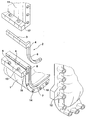
- FIG. 1 An embodiment of the invention is shown in the drawing and is in following described in more detail. It shows the only figure, a fragmentary, three-dimensional exploded view of the sealing arrangement in the range from vertical abutting edge portions of an oil pan of an internal combustion engine, the one forms the first wall element with a protruding corner.
- the fragmentary oil pan 1 shown in the figure is on the one hand at its edges sealingly connected to the flange of a crankcase 11 and the other to one Flange on a housing that a device carrier 12 for a not shown Internal combustion engine forms.
- the crankcase 11 and the equipment carrier 12 are also as shown only one fragment of the oil pan 1.
- the oil pan is 1 on the entire upper edge of the crankcase 11 and also on the end face on the entire front edge on the equipment carrier 12.
- a wall piece of the equipment carrier forms with a wall piece of the crankcase together a second, with an inner corner formed wall element with the first, formed with an outer corner Wall element complementary edges.
- the oil pan 1 is along the edges with grooves 6, 7, into which one consists of three sealing sections 3, 4 and 5 rubber-elastic seal 2 can be inserted.
- the seal 2 can for example a circular or rectangular or any other cross-sectional shape exhibit.
- the groove depth and the seal diameter are coordinated so that after the attachment of the equipment carrier 12 or the attachment of the oil pan 1 to the crankcase 11 the seal with a press fit on the contact surfaces on the crankcase and on the equipment carrier is present.
- the oil pan has a circumferential flange with threaded holes 13 and 14 trained to attach the oil pan 1 to corresponding flanges of the Serve crankcase 11 and the device carrier 12 by means of screws.
- the device carrier is at the same time also attached to a surface 17 of the crankcase in the same
- the plane runs like a surface 10 on the end face of the oil pan.
- the sealing section 4, shown here in one piece with the sealing sections 3 and 5 comes in a To lie recess 8, which runs parallel to an edge 16.
- the edge 16 is formed as the intersection of the surfaces 9 and 10, which represent the edges of the oil pan 1.
- the Recess 8 represents a right-angled milling, which is from the crankcase side or can be incorporated from the equipment carrier side.
- the depth of the cut corresponds to the groove depths of the grooves 6 and 7.
- the recess 8 connects the grooves 6 and 7, in the edge 16 with an offset transverse to the direction of extension of the seal leak.
- the recess 8 running in the direction of the edge 16 serves for receiving of the sealing section 4.
- the sealing section 4 projects beyond the surface 9 and the surface 10 in the same way as the sealing sections 3 and 5 do. After oil pan and Device carriers are screwed, the sealing section 4 is therefore with a press fit on Crankcase and on the housing of the equipment rack. This will make a flawless and permanent sealing of the edge area achieved.
- the seal is deflected now no longer in a plane perpendicular to the surfaces 9, 10, but in two steps each in planes that are parallel to the surfaces 9, 10.
- the seal 2 can be formed in one piece.
- the sealing section 4 can also than to the sealing sections 3 and 5 separately, or only with one of the Sealing sections 3 or 5 may be coherent.
- the seal between the housing of the equipment rack and the crankcase is made in surface 17, for example by means of a curable applied to the surface Sealing paste.
- a groove corresponding to the grooves 6 can also be used and 7 may be provided in which a sealing portion like that for the seal 2 used sealing sections can be arranged.
Landscapes
- Engineering & Computer Science (AREA)
- General Engineering & Computer Science (AREA)
- Mechanical Engineering (AREA)
- Physics & Mathematics (AREA)
- Geometry (AREA)
- Cylinder Crankcases Of Internal Combustion Engines (AREA)
- Lubrication Details And Ventilation Of Internal Combustion Engines (AREA)
- Gasket Seals (AREA)
Abstract
Description
Claims (9)
- Dichtanordnung entlang winkelbildender Ränder eines insbesondere zu einem ersten Gehäuse, insbesondere einer Ölwanne einer Brennkraftmaschine gehörigen ersten Wandelements mit einer Außenecke, das in dichtender Verbindung mit komplementären Rändern eines zweiten Wandelements mit einer Innenecke, insbesondere zweiter Gehäuse, insbesondere eines Kurbelgehäuses und eines Geräteträgers der Brennkraftmaschine steht, wobei die die Dichtflächen darstellenden Ränder des ersten und zweiten Wandelements in den Ecken jeweils quer zu den Ebenen der Wandelemente verlaufende Kanten ausbilden, wobei ferner zur Abdichtung in den Dichtflächen des ersten und/oder zweiten Wandelements Nuten vorgesehen sind, in die eine Dichtung eingelegt ist, dadurch gekennzeichnet, daß die Nuten (6, 7) im Bereich der Kante (16) mit einem Versatz quer zur Längserstreckungsrichtung der Dichtung (3, 5) verlaufen, und daß in der Kante (16) eine die Nuten (6, 7) verbindende, in Erstreckungrichtung der Kante (16) verlaufende Ausnehmung (8) zur Anordnung eines in Richtung der Kante (16) verlaufenden Dichtungsabschnitts (4) vorgesehen ist.
- Dichtanordnung nach Anspruch 1, dadurch gekennzeichnet, daß das zweite Wandelement aus zwei Wandstücken zweier Gehäuse, nämlich einem Wandstück mit einer Ecke und einem Wandstück mit geradem Rand zusammengesetzt ist, die die zum ersten Wandelement komplementären Ränder ausbilden.
- Dichtanordnung nach Anspruch 1 oder 2, dadurch gekennzeichnet, daß die vorspringende Ecke des ersten Wandelements mit einem rechten Winkel ausgebildet ist.
- Dichtanordnung nach Anspruch 1, 2 oder 3, dadurch gekennzeichnet, daß die Dichtung (2) einstückig ausgebildet ist.
- Dichtanordnung nach Anspruch 1, 2 oder 3, dadurch gekennzeichnet, daß der Dichtungsabschnitt (4) als ein zu Dichtungsabschnitten (3 und 5) in den Nuten (6 und 7) separater Dichtungsabschnitt ausgebildet ist.
- Dichtanordnung nach Anspruch 1, 2 oder 3, dadurch gekennzeichnet, daß der Dichtungsabschnitt (4) entweder mit einem Dichtungsabschnitt (5) in der Nut (7) oder einem Dichtungsabschnitt (3) in der Nut (6) zusammenhängend ausgebildet ist.
- Dichtanordnung nach einem der Ansprüche 1 bis 6, dadurch gekennzeichnet, daß Nuten (6, 7) und die Ausnehmung (8) zur Aufnahme der Dichtungsabschnitte (3, 4 oder 5) im ersten und/oder im zweiten Wandelement angeordnet sind.
- Dichtanordnung nach einem der Ansprüche 1 bis 7, dadurch gekennzeichnet, daß die Tiefe der Ausnehmung (8) den Nuttiefen der Nuten (6, 7) entspricht.
- Dichtanordnung nach einem der Ansprüche 1 bis 8, dadurch gekennzeichnet, daß die Nuten (6, 7) und die Ausnehmung (8) so dimensioniert sind, daß die darin aufgenommene Dichtung (2) über die Dichtflächen übersteht, wenn die komplementären Wandelemente unverbunden sind.
Applications Claiming Priority (2)
| Application Number | Priority Date | Filing Date | Title |
|---|---|---|---|
| DE19638817A DE19638817A1 (de) | 1996-09-20 | 1996-09-20 | Dichtanordnung entlang zweier winkelbildener Ränder eines flächenhaften Wandelements |
| DE19638817 | 1996-09-20 |
Publications (3)
| Publication Number | Publication Date |
|---|---|
| EP0831258A2 true EP0831258A2 (de) | 1998-03-25 |
| EP0831258A3 EP0831258A3 (de) | 1998-04-01 |
| EP0831258B1 EP0831258B1 (de) | 2004-08-11 |
Family
ID=7806499
Family Applications (1)
| Application Number | Title | Priority Date | Filing Date |
|---|---|---|---|
| EP97116139A Expired - Lifetime EP0831258B1 (de) | 1996-09-20 | 1997-09-17 | Dichtanordnung entlang zweier winkelbildender Ränder eines Wandelements |
Country Status (4)
| Country | Link |
|---|---|
| US (1) | US5934686A (de) |
| EP (1) | EP0831258B1 (de) |
| DE (2) | DE19638817A1 (de) |
| ES (1) | ES2227641T3 (de) |
Cited By (2)
| Publication number | Priority date | Publication date | Assignee | Title |
|---|---|---|---|---|
| EP4033075A1 (de) * | 2021-01-22 | 2022-07-27 | Liebherr-Components Colmar SAS | Ölwannenanordnung |
| US11739668B2 (en) | 2021-01-22 | 2023-08-29 | Liebherr-Components Colmar Sas | Sealing arrangement |
Families Citing this family (12)
| Publication number | Priority date | Publication date | Assignee | Title |
|---|---|---|---|---|
| DE19818593C2 (de) * | 1998-04-25 | 2000-03-30 | Daimler Chrysler Ag | Kurbelgehäuse einer Brennkraftmaschine |
| JP4344460B2 (ja) * | 2000-07-11 | 2009-10-14 | 本田技研工業株式会社 | エンジン本体のシール構造 |
| JP4258803B2 (ja) * | 2003-03-26 | 2009-04-30 | シーワイジー技術研究所株式会社 | 真空チャンバ組立体 |
| US20050183824A1 (en) * | 2004-02-25 | 2005-08-25 | Advanced Display Process Engineering Co., Ltd. | Apparatus for manufacturing flat-panel display |
| DE102004026065A1 (de) * | 2004-05-25 | 2005-12-15 | Huf Hülsbeck & Fürst GmbH & Co KG | Motorisch betätigbares Schloss für Türen oder Klappen von Fahrzeugen |
| US7267092B2 (en) * | 2005-11-18 | 2007-09-11 | Husqvarna Outdoor Products Inc. | Apparatus including a preformed one-piece seal |
| US7753379B2 (en) * | 2007-02-20 | 2010-07-13 | Freudenberg-Nok General Partnership | Gasket with transition sealing feature |
| US7845331B2 (en) * | 2007-11-21 | 2010-12-07 | Husqvarna Outdoor Products Inc. | Seal structure for internal combustion engine |
| JP5969428B2 (ja) * | 2013-06-27 | 2016-08-17 | トヨタ自動車株式会社 | オイルパン |
| US9845874B2 (en) * | 2014-02-06 | 2017-12-19 | General Electric Company | Compression seal bracket and system for generator cooler |
| US11242779B1 (en) * | 2020-10-14 | 2022-02-08 | Kohler Co. | Engine lubrication system |
| CN112879120A (zh) * | 2021-01-26 | 2021-06-01 | 东风汽车集团股份有限公司 | 油底壳密封结构、方法、发动机及汽车 |
Family Cites Families (9)
| Publication number | Priority date | Publication date | Assignee | Title |
|---|---|---|---|---|
| US2753827A (en) * | 1951-10-06 | 1956-07-10 | Alvin R Campbell Co Inc | Ship hatch cover structure |
| US4394853A (en) * | 1981-06-22 | 1983-07-26 | General Motors Corporation | Engine oil pan isolation mounting |
| US4597583A (en) * | 1985-07-08 | 1986-07-01 | Felt Products Mfg. Co. | Gasket assembly for sealing covers to automotive engines |
| JPH0413402Y2 (de) * | 1986-04-23 | 1992-03-27 | ||
| US4669432A (en) * | 1986-05-16 | 1987-06-02 | Kabushiki Kaisha Komatsu Seisakusho | Sealing device for an oil pan adapter in an internal combustion engine |
| DE3815511A1 (de) * | 1988-05-06 | 1989-11-16 | Daimler Benz Ag | Gummielastische abdichtung zwischen zwei loesbaren gehaeuseteilen, insbesondere solche zwischen einer oelwanne und einem getriebegehaeuse fuer einen fahrzeugantrieb |
| US5222745A (en) * | 1992-02-28 | 1993-06-29 | Jmk International, Inc. | RTV-less gasket assembly |
| US5218938A (en) * | 1992-11-02 | 1993-06-15 | General Motors Corporation | Structural oil pan for internal combustion engine |
| JPH09209150A (ja) * | 1996-02-06 | 1997-08-12 | Tokyo Electron Ltd | 真空チャンバ及びその製造方法 |
-
1996
- 1996-09-20 DE DE19638817A patent/DE19638817A1/de not_active Withdrawn
-
1997
- 1997-09-17 EP EP97116139A patent/EP0831258B1/de not_active Expired - Lifetime
- 1997-09-17 ES ES97116139T patent/ES2227641T3/es not_active Expired - Lifetime
- 1997-09-17 DE DE59711844T patent/DE59711844D1/de not_active Expired - Lifetime
- 1997-09-19 US US08/934,476 patent/US5934686A/en not_active Expired - Lifetime
Cited By (4)
| Publication number | Priority date | Publication date | Assignee | Title |
|---|---|---|---|---|
| EP4033075A1 (de) * | 2021-01-22 | 2022-07-27 | Liebherr-Components Colmar SAS | Ölwannenanordnung |
| US11619151B2 (en) | 2021-01-22 | 2023-04-04 | Liebherr-Components Colmar Sas | Oil pan assembly |
| US11739668B2 (en) | 2021-01-22 | 2023-08-29 | Liebherr-Components Colmar Sas | Sealing arrangement |
| EP4033076B1 (de) * | 2021-01-22 | 2024-08-07 | Liebherr-Components Colmar SAS | Dichtungsanordnung |
Also Published As
| Publication number | Publication date |
|---|---|
| EP0831258B1 (de) | 2004-08-11 |
| DE59711844D1 (de) | 2004-09-16 |
| EP0831258A3 (de) | 1998-04-01 |
| ES2227641T3 (es) | 2005-04-01 |
| DE19638817A1 (de) | 1998-03-26 |
| US5934686A (en) | 1999-08-10 |
Similar Documents
| Publication | Publication Date | Title |
|---|---|---|
| DE2515939C3 (de) | Thermoplastklernmuffe mit Dichtungskörper | |
| EP0831258B1 (de) | Dichtanordnung entlang zweier winkelbildender Ränder eines Wandelements | |
| EP1524731B1 (de) | Steckergehäuse mit verbesserter Kabelabdichtung | |
| DE2807860A1 (de) | Verbinder fuer lichtleitmonofasern | |
| DE10108925B4 (de) | Magneto-striktive Wegmeß-Vorrichtung | |
| EP4133913B1 (de) | Gehäuse mit integrierten schutzabschnitt umfassenden gehäuseteil | |
| EP1750109A1 (de) | Drehmomentsensor und Verfahren zu dessen Herstellung | |
| DE19828838B4 (de) | Vorrichtung zur abgedichteten Verlegung von Rohren, Kabeln, Leitungen oder dergleichen Langformteilen durch Gerätewandungen | |
| EP1503460B1 (de) | Kabelabdichtung für einen Steckverbinder | |
| WO2020083886A1 (de) | Elektrischer Stecker, elektrisches Gerät, elektrische Steckverbindung und Verfahren zur Herstellung eines elektrischen Geräts | |
| DE2425121A1 (de) | Verbindungseinrichtung fuer leitungen | |
| DE10118387A1 (de) | Getriebe, insbesondere Schneckengetriebe | |
| DE19629352A1 (de) | Adaptervorrichtung für eine Ratsche | |
| EP0283696B1 (de) | Elastomerdichtung | |
| DE112019007818T5 (de) | Abflussstopfen mit perimeterlabyrinth für gehäuse von rotierenden elektrischen maschinen und entsprechendes gehäuse | |
| WO2005100907A2 (de) | Wegmess-vorrichtung | |
| CH659341A5 (de) | Scheibenisolator mit aeusserem armaturring und verfahren zu dessen herstellung. | |
| DE602004001959T2 (de) | Dichtungsanordnung einer Einspritzdüsenbohrung | |
| DE2805609C2 (de) | ||
| DE10307532B4 (de) | Anordnung zum Anschluß einer Vakuumleitung an eine Kraftfahrzeugkomponente, insbesondere an einen Bremskraftverstärker | |
| EP0791739B1 (de) | Verschlussdeckel, insbesondere für Motor- und Getriebegehäuse bei Kraftfahrzeugen | |
| DE102016206242B4 (de) | Vorrichtung zur Abdichtung zwischen zwei miteinander verbundenen Gehäuseteilen, sowie Ölwanne | |
| DE202006018042U1 (de) | Dichtung für Flanschsteckerverbinder | |
| WO2020083889A1 (de) | Elektrischer stecker, elektrisches gerät und verfahren zur herstellung eines elektrischen geräts | |
| EP0778651B1 (de) | Anordnung zum Anschluss eines Geräte-Anschlusskabels |
Legal Events
| Date | Code | Title | Description |
|---|---|---|---|
| PUAI | Public reference made under article 153(3) epc to a published international application that has entered the european phase |
Free format text: ORIGINAL CODE: 0009012 |
|
| PUAL | Search report despatched |
Free format text: ORIGINAL CODE: 0009013 |
|
| AK | Designated contracting states |
Kind code of ref document: A2 Designated state(s): DE ES FR GB IT |
|
| AX | Request for extension of the european patent |
Free format text: AL;LT;LV;RO;SI |
|
| AK | Designated contracting states |
Kind code of ref document: A3 Designated state(s): AT BE CH DE DK ES FI FR GB GR IE IT LI LU MC NL PT SE |
|
| AX | Request for extension of the european patent |
Free format text: AL;LT;LV;RO;SI |
|
| 17P | Request for examination filed |
Effective date: 19980226 |
|
| AKX | Designation fees paid |
Free format text: DE ES FR GB IT |
|
| RBV | Designated contracting states (corrected) |
Designated state(s): DE ES FR GB IT |
|
| 17Q | First examination report despatched |
Effective date: 20010831 |
|
| RAP1 | Party data changed (applicant data changed or rights of an application transferred) |
Owner name: MTU FRIEDRICHSHAFEN GMBH |
|
| GRAG | Despatch of communication of intention to grant |
Free format text: ORIGINAL CODE: EPIDOS AGRA |
|
| GRAG | Despatch of communication of intention to grant |
Free format text: ORIGINAL CODE: EPIDOS AGRA |
|
| GRAG | Despatch of communication of intention to grant |
Free format text: ORIGINAL CODE: EPIDOS AGRA |
|
| GRAJ | Information related to disapproval of communication of intention to grant by the applicant or resumption of examination proceedings by the epo deleted |
Free format text: ORIGINAL CODE: EPIDOSDIGR1 |
|
| GRAP | Despatch of communication of intention to grant a patent |
Free format text: ORIGINAL CODE: EPIDOSNIGR1 |
|
| GRAS | Grant fee paid |
Free format text: ORIGINAL CODE: EPIDOSNIGR3 |
|
| GRAI | Information related to approval/disapproval following communication of intention to grant deleted |
Free format text: ORIGINAL CODE: EPIDOSDAGR3 |
|
| GRAO | Approval/disapproval following communication of intention to grant |
Free format text: ORIGINAL CODE: EPIDOSNAGR3 |
|
| GRAA | (expected) grant |
Free format text: ORIGINAL CODE: 0009210 |
|
| AK | Designated contracting states |
Kind code of ref document: B1 Designated state(s): DE ES FR GB IT |
|
| REG | Reference to a national code |
Ref country code: GB Ref legal event code: FG4D Free format text: NOT ENGLISH |
|
| REF | Corresponds to: |
Ref document number: 59711844 Country of ref document: DE Date of ref document: 20040916 Kind code of ref document: P |
|
| GBT | Gb: translation of ep patent filed (gb section 77(6)(a)/1977) |
Effective date: 20041027 |
|
| REG | Reference to a national code |
Ref country code: ES Ref legal event code: FG2A Ref document number: 2227641 Country of ref document: ES Kind code of ref document: T3 |
|
| ET | Fr: translation filed | ||
| PLBE | No opposition filed within time limit |
Free format text: ORIGINAL CODE: 0009261 |
|
| STAA | Information on the status of an ep patent application or granted ep patent |
Free format text: STATUS: NO OPPOSITION FILED WITHIN TIME LIMIT |
|
| 26N | No opposition filed |
Effective date: 20050512 |
|
| PGFP | Annual fee paid to national office [announced via postgrant information from national office to epo] |
Ref country code: FR Payment date: 20050823 Year of fee payment: 9 |
|
| PGFP | Annual fee paid to national office [announced via postgrant information from national office to epo] |
Ref country code: GB Payment date: 20050905 Year of fee payment: 9 |
|
| PGFP | Annual fee paid to national office [announced via postgrant information from national office to epo] |
Ref country code: ES Payment date: 20050921 Year of fee payment: 9 |
|
| PGFP | Annual fee paid to national office [announced via postgrant information from national office to epo] |
Ref country code: IT Payment date: 20060930 Year of fee payment: 10 |
|
| GBPC | Gb: european patent ceased through non-payment of renewal fee |
Effective date: 20060917 |
|
| REG | Reference to a national code |
Ref country code: FR Ref legal event code: ST Effective date: 20070531 |
|
| PG25 | Lapsed in a contracting state [announced via postgrant information from national office to epo] |
Ref country code: GB Free format text: LAPSE BECAUSE OF NON-PAYMENT OF DUE FEES Effective date: 20060917 |
|
| REG | Reference to a national code |
Ref country code: ES Ref legal event code: FD2A Effective date: 20060918 |
|
| PG25 | Lapsed in a contracting state [announced via postgrant information from national office to epo] |
Ref country code: ES Free format text: LAPSE BECAUSE OF NON-PAYMENT OF DUE FEES Effective date: 20060918 |
|
| PG25 | Lapsed in a contracting state [announced via postgrant information from national office to epo] |
Ref country code: FR Free format text: LAPSE BECAUSE OF NON-PAYMENT OF DUE FEES Effective date: 20061002 |
|
| PG25 | Lapsed in a contracting state [announced via postgrant information from national office to epo] |
Ref country code: IT Free format text: LAPSE BECAUSE OF NON-PAYMENT OF DUE FEES Effective date: 20070917 |
|
| PGFP | Annual fee paid to national office [announced via postgrant information from national office to epo] |
Ref country code: DE Payment date: 20140922 Year of fee payment: 18 |
|
| REG | Reference to a national code |
Ref country code: DE Ref legal event code: R119 Ref document number: 59711844 Country of ref document: DE |
|
| PG25 | Lapsed in a contracting state [announced via postgrant information from national office to epo] |
Ref country code: DE Free format text: LAPSE BECAUSE OF NON-PAYMENT OF DUE FEES Effective date: 20160401 |