EP0830981B1 - Automatische Verriegelung für Container, Wechselbehälter oder dergleichen - Google Patents
Automatische Verriegelung für Container, Wechselbehälter oder dergleichen Download PDFInfo
- Publication number
- EP0830981B1 EP0830981B1 EP97250250A EP97250250A EP0830981B1 EP 0830981 B1 EP0830981 B1 EP 0830981B1 EP 97250250 A EP97250250 A EP 97250250A EP 97250250 A EP97250250 A EP 97250250A EP 0830981 B1 EP0830981 B1 EP 0830981B1
- Authority
- EP
- European Patent Office
- Prior art keywords
- clamping bolt
- transport
- loading surface
- piston
- guide part
- Prior art date
- Legal status (The legal status is an assumption and is not a legal conclusion. Google has not performed a legal analysis and makes no representation as to the accuracy of the status listed.)
- Expired - Lifetime
Links
- 238000013016 damping Methods 0.000 claims 1
- 230000006835 compression Effects 0.000 description 3
- 238000007906 compression Methods 0.000 description 3
- 238000000034 method Methods 0.000 description 3
- 230000000694 effects Effects 0.000 description 1
- 238000005516 engineering process Methods 0.000 description 1
- 238000003780 insertion Methods 0.000 description 1
- 230000037431 insertion Effects 0.000 description 1
- 238000009434 installation Methods 0.000 description 1
- 230000000149 penetrating effect Effects 0.000 description 1
- 230000000284 resting effect Effects 0.000 description 1
- 238000009420 retrofitting Methods 0.000 description 1
Images



Classifications
-
- B—PERFORMING OPERATIONS; TRANSPORTING
- B60—VEHICLES IN GENERAL
- B60P—VEHICLES ADAPTED FOR LOAD TRANSPORTATION OR TO TRANSPORT, TO CARRY, OR TO COMPRISE SPECIAL LOADS OR OBJECTS
- B60P7/00—Securing or covering of load on vehicles
- B60P7/06—Securing of load
- B60P7/13—Securing freight containers or forwarding containers on vehicles
- B60P7/132—Securing freight containers or forwarding containers on vehicles twist-locks for containers or frames
Definitions
- the invention relates to a lock for standardized transport containers such as containers, swap bodies or the like.
- clamping bolts On loading areas of means of transport, by means of clamping bolts, which can be at least partially moved upwards out of their rest positions below the loading area into vertical operative positions from the loading area and in this position with their at their free ends provided clamping bolt heads can be locked in openings in the corner areas of the transport container, wherein each clamping bolt is part of a vertically acting piston-cylinder unit, which is attached to the frame of the means of transport below the loading surface, the vertical stroke of each piston-cylinder unit corresponds to the extension path of the clamping bolt with the clamping bolt head upwards out of the loading area, the bolt head is designed like a hammer head and engage motor means on the circumference of the clamping bolt with which the clamping bolt with the clamping bolt head can be pivoted through 90 ° about its vertical axis, wherein each clamping bolt is concentrically connected to the piston of the piston-cylinder unit and the clamping bolt can be extended into an end
- Such a lock is known from GB -A- 1199594.
- DE 23 43 251 A1 discloses a device for fixing containers on a loading surface, in which the clamping bolt is part of a vertically acting piston-cylinder unit. Appropriate guides ensure that the clamping bolt can carry out a translatory or a translatory-rotating movement. The head of the clamping bolt is not completely lowered below the loading area.
- the object of the present invention is an automatic Locking for standardized transport containers such as containers, swap bodies or to create the same on the loading surfaces of transport vehicles, for example can be activated and locked remotely.
- each clamping bolt head below its clamping bolt head is coaxially surrounded by a guide piece that can be displaced in the longitudinal axis direction on the clamping pin, which together with the clamping pin in a bore corresponding to the contour of the guide piece in the loading area of the transport means can be moved into a position limiting its stroke, in which at least part of the guide piece engaging behind the clamping bolt head protrudes from the loading area and that the clamping bolt head can be locked in an end position after pivoting about its vertical axis and retracting the piston of the piston-cylinder unit with the transport container.
- twist locks on the spreader To provide sling gear for ISO containers, in which, however, the installation position of the Twist locks is rotated by 180 °. So the load hangs in the twist locks.
- a lever arm that is spread apart laterally from this below the loading surface is arranged, on which a pivot cylinder engages with the frame the loading area is connected.
- the invention is an intelligent addition at the interface between conveyor technology and transport system have been created.
- the invention also makes this possible Retrofitting conventional transport systems with cheap facilities, see above that these transport systems faster and faster by reducing idle times so that can be made more economical.
- FIG 1 the loading area of a means of transport for 20 and 40 ft ISO containers and shown for swap bodies.
- 12 points for cargo locking for the means of transport provided to these transport containers on the loading area too Fasten.
- the 12 points are labeled 1, 2.1 and 2.2.
- points 1 or points 2.1 and 2.2 are required.
- Each of these points for securing the cargo contains the invention Tensioning bolt of the locking device, described in detail below becomes.
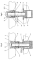
- the locking according to the invention in the deactivated position is schematic shown. It consists of the bore 4 penetrating the loading area 3, in which the clamping bolt 6 is guided, the clamping bolt head at its free end 7 carries.
- This clamping bolt head 7 is designed like a hammer head, i.e. in its Projection, the clamping bolt head 7 is essentially rectangular.
- the pressure medium can be applied on both sides.
- the guide piece 11 is concentric to the longitudinal axis 10 of the clamping bolt 6 the clamping bolt 6 slidably arranged, the outer contour of the outer contour of the bolt head 7 corresponds.
- the guide piece 11 is deposited at 12; on Corresponding paragraph 13 is provided in the bore 4 and forms a stop for the guide piece 11 in the extended position of the piston 8, such as it is shown in Figure 3.
- part 14 of the guide piece protrudes 11 out of the loading area 3, the clamping bolt head 7 on the end face on the Guide piece 11 rests.
- a compression spring 15 between the guide piece 11 and a flange 16 on the clamping bolt 6 causes the guide piece 11 against the stop 12 or 13 pressed on the loading surface 3 or on the guide piece 11 becomes.
- the flange washer is designed in two parts for assembly.
- Figure 3 is also recognizable the piston 8 of the piston-cylinder unit 9 is not fully extended. In 3, as can be seen better in FIG.
- the transport container 17th is passed through the clamping bolt head 7 and its shape, so that the transport container 17 centered on the bed 3 can be placed.
- FIG Pressurized medium is applied so that the piston reaches an end position, whereby it is in the Cylinder of the piston-cylinder unit 9 comes to rest.
- the one with the Piston 8 connected clamping bolt 6 moved further in the direction of its longitudinal axis 10, namely through the guide piece 11, one on the Back of the bolt head 7 molded square piece 19 from the guide piece 11 stands out.
- the compression spring 15 is compressed and holds the guide piece 11 against the contact surface 12, 13 in position.
- figure 7 shows the arrangement according to FIG. 6 in a top view.
- FIG. 6 the lever arm that spreads laterally from the clamping bolt 6 is also at 20 recognizable, on which the schematically indicated pivot cylinder 21 acts.
- this lever arm By pivoting this lever arm by 90 °, the one shown in FIG Position of the lock according to the invention reached.
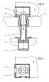
- the can be seen Hammer head-like clamping bolt head 7 with the clamping bolt 6 by 90 ° in the guide piece 11 rotated so that the clamping bolt head, as in FIG. 9 recognizable, now transversely to the recess 18 in the corner fitting of the transport container 17 stands.
- the piston 8 of the piston-cylinder unit 9 is in the Entry direction pressurized so that the clamping bolt head 7 against the Corner fitting of the container 17 is pulled, whereby the transport container 17 on the loading area 3 is jammed.
- FIG. 6 which is shown again in FIG Top view is shown, the load is secure against slipping on the loading surface fixed and can only be unlocked by reversing the movement.
- the present lock allows the possibility of lowering the Of the load bolt even when the load bolt is not used. Only when the clamping bolts are needed to secure the load, they become moved from the lowered position through the loading area 3 upwards, whereby secure positioning together with the guide piece according to the invention and centering the load and after turning the clamping bolt head and clamping enable the transport containers to be held securely on the loading surface 3.
Landscapes
- Engineering & Computer Science (AREA)
- Transportation (AREA)
- Mechanical Engineering (AREA)
- Specific Conveyance Elements (AREA)
- Load-Engaging Elements For Cranes (AREA)
- Forklifts And Lifting Vehicles (AREA)
- Feeding Of Articles To Conveyors (AREA)
- Clamps And Clips (AREA)
- Hand Tools For Fitting Together And Separating, Or Other Hand Tools (AREA)
- Pressure Vessels And Lids Thereof (AREA)
- Lock And Its Accessories (AREA)
- Details Of Rigid Or Semi-Rigid Containers (AREA)
Description
wobei jeder Spannbolzen Teil einer vertikal wirkenden Kolben-Zylindereinheit ist, die unterhalb der Ladefläche am Rahmen des Transportmittels befestigt ist,
der Vertikalhub jeder Kolben-Zylindereinheit dem Ausfahrweg des Spannbolzens mit dem Spannbolzenkopf nach oben aus der Ladefläche heraus entspricht,
der Spannbolzenkopf hammerkopfartig gestaltet ist und
am Umfang des Spannbolzens motorische Mittel angreifen, mit denen der Spannbolzen mit dem Spannbolzenkopf um 90° um seine Vertikalachse verschwenkbar ist,
wobei ferner jeder Spannbolzen mit dem Kolben der Kolben-Zylindereinheit konzentrisch verbunden ist und
der Spannbolzen gegen die Wirkung einer Federkraft bis in eine Endstellung ausfahrbar ist.
Aus der DE 23 43 251 A1 ist eine Vorrichtung zum Fixieren von Containern auf einer Ladefläche bekannt, bei der der Spannbolzen Teil einer vertikal wirkenden Kolben-Zylindereinheit ist. Durch entsprechende Führungen wird erreicht, daß der Spannbolzen eine translatorische bzw. eine translatorisch-rotierende Bewegung ausführen kann. Der Kopf des Spannbolzens wird aber nicht vollständig unter die Ladefläche abgesenkt.
dass der Spannbolzenkopf in einer Endstellung nach dem Verschwenken um seine Vertikalachse und Einfahren des Kolbens der Kolben-Zylindereinheit mit dem Transportbehälter verriegelbar ist.
- Figur 1
- die Draufsicht auf die Ladefläche eines Transportmittels,
- Figur 2
- die erfindungsgemäße Verriegelung in deaktivierter Position,
- Figuren 3-7
- verschiedene Verriegelungspositionen in entriegelter Stellung,
- Figur 8
- die Verriegelung aktiv während des Verriegelungsvorganges,
- Figur 9
- eine Draufsicht auf Figur 8,
- Figur 10
- die Verriegelung in der Position nach dem Verriegelungsvorgang, und
- Figur 11
- eine Draufsicht auf Figur 10.
Claims (5)
- Verriegelung für genormte Transportbehälter wie Container, Wechselbehälter oder dergl. auf Ladeflächen von Transportmitteln, mittels Spannbolzen, die aus ihren Ruhestellungen unterhalb der Ladefläche in vertikale Wirkstellungen aus der Ladefläche mindestens teilweise nach oben herausbewegbar sind und in dieser Stellung mit ihren an ihren freien Enden vorgesehenen Spannbolzenköpfen in Öffnungen in den Eckbereichen der Transportbehälter verriegelbar sind,
wobei jeder Spannbolzen (6) Teil einer vertikal wirkenden Kolben-Zylindereinheit (9) ist, die unterhalb der Ladefläche (3) am Rahmen (5) des Transportmittels befestigt ist,
der Vertikalhub jeder Kolben-Zylindereinheit (9) dem Ausfahrweg des Spannbolzens (6) mit dem Spannbolzenkopf (7) nach oben aus der Ladefläche (3) heraus entspricht,
der Spannbolzenkopf (7) hammerkopfartig gestaltet ist und
am Umfang des Spannbolzens (6) motorische Mittel (21) angreifen, mit denen der Spannbolzen (6) mit dem Spannbolzenkopf (7) um 90° um seine Vertikalachse (10) verschwenkbar ist,
wobei femer jeder Spannbolzen (6) mit dem Kolben der Kolben-Zylindereinheit (9) konzentrisch verbunden ist und
der Spannbolzen (6) gegen die Wirkung einer Federkraft (15) bis in eine Endstellung ausfahrbar ist,
dadurch gekennzeichnet, dass jeder Spannbolzenkopf (6) unterhalb seines Spannbolzenkopfes (7) koaxial von einem auf dem Spannbolzen (6) in seiner Längsachsrichtung (10) verschiebbaren Führungsstück (11) umgeben ist, das gemeinsam mit dem Spannbolzen (6) in einer der Kontur des Führungsstückes (11) entsprechenden Bohrung (4) in der Ladefläche (3) des Transportmittels in eine seinen Hub begrenzende Stellung bewegbar ist, in der mindestens ein Teil des den Spannbolzenkopf (7) stimseitig hintergreifenden Führungsstückes (11) aus der Ladefläche (3) herausragt und
dass der Spannbolzenkopf (7) in einer Endstellung nach dem Verschwenken um seine Vertikalachse (10) und Einfahren des Kolbens (8) der Kolben-Zylindereinheit (9) mit dem Transportbehälter (17) verriegelbar ist. - Verriegelung für genormte Transportbehälter nach Anspruch 1, dadurch gekennzeichnet dass die Projektionen des Spannbolzenkopfes (7) und des Führungsstückes (11) auf eine senkrecht zur Längsachsrichtung (10) des Spannbolzens (6) gesehene Projektionsebene deckungsgleich sind
- Verriegelung für genormte Transportbehälter nach Anspruch 1 bis 2 dadurch gekennzeichnet dass zur Hubbegrenzung des Führungsstückes (11) in den Bohrungen (4) der Ladefläche (3) jeweils den Querschnitt der Bohrungen verringemde Absätze (13) vorgesehen ist, hinter denen jeweils der an den Führungsstücken (11) vorgesehene Absatz (12) zur Anlage bringbar ist, wobei die Absätze (12,13) so angeordnet sind, dass die zur Verriegelung des Transportbehälters (17) notwendige Länge des Führungsstückes (11) aus der Ladefläche (3) herausragen.
- Verriegelung für genormte Transportbehälter nach Anspruch 1 bis 3 dadurch gekennzeichnet dass zwischen dem Führungsstück (11) und einer am Spannbolzen (6) vorgesehenen Bundscheibe (16) eine Druckfeder (15), den Spannbolzen (6) konzentrisch umfassend, angeordnet ist, deren Federkraft mindestens der Gewichtskraft des Führungsstückes (11) entspricht.
- Verriegelung für genormte Transportbehälter nach Anspruch 1 bis 4 dadurch gekennzeichnet dass zum Verschwenken des Spannbolzens (6) ein seitlich von diesem abgespreizter Hebelarm (20) unterhalb der Ladefläche (3) angeordnet ist, an dem ein Schwenkzylinder (21) angreift, der mit dem Rahmen (5) der Ladefläche (3) verbunden ist.
Applications Claiming Priority (2)
| Application Number | Priority Date | Filing Date | Title |
|---|---|---|---|
| DE19639988A DE19639988C2 (de) | 1996-09-18 | 1996-09-18 | Automatische Verriegelung für Container, Wechselbehälter oder dergl. |
| DE19639988 | 1996-09-18 |
Publications (3)
| Publication Number | Publication Date |
|---|---|
| EP0830981A2 EP0830981A2 (de) | 1998-03-25 |
| EP0830981A3 EP0830981A3 (de) | 1998-07-08 |
| EP0830981B1 true EP0830981B1 (de) | 2003-05-02 |
Family
ID=7807217
Family Applications (1)
| Application Number | Title | Priority Date | Filing Date |
|---|---|---|---|
| EP97250250A Expired - Lifetime EP0830981B1 (de) | 1996-09-18 | 1997-08-27 | Automatische Verriegelung für Container, Wechselbehälter oder dergleichen |
Country Status (8)
| Country | Link |
|---|---|
| US (1) | US5927916A (de) |
| EP (1) | EP0830981B1 (de) |
| JP (1) | JP4023564B2 (de) |
| AT (1) | ATE238926T1 (de) |
| DE (2) | DE19639988C2 (de) |
| DK (1) | DK0830981T3 (de) |
| ES (1) | ES2192651T3 (de) |
| PT (1) | PT830981E (de) |
Families Citing this family (42)
| Publication number | Priority date | Publication date | Assignee | Title |
|---|---|---|---|---|
| DE19603817A1 (de) * | 1996-02-02 | 1997-10-09 | Gerd Schulz | Vorrichtung zur Verriegelung eines Containers an einem Fahrzeugchassis |
| DE19720238A1 (de) * | 1997-05-14 | 1998-11-19 | Frank P Schulz | Verriegelung für Container an einem Fahrzeugchassis |
| US6533511B1 (en) | 1999-12-03 | 2003-03-18 | Holland Company | Movable container lock for shipping containers |
| GB2356891B (en) * | 1999-12-03 | 2003-09-17 | Holland Co | Lock assembly for securing shipping containers |
| KR100351793B1 (ko) * | 2000-01-27 | 2002-09-11 | 금명정밀공업 주식회사 | 트레일러용 컨테이너의 자동 록킹장치 |
| GB0122181D0 (en) * | 2001-09-14 | 2001-10-31 | Reynard Kenneth | Self-cleaning rotatable clamping device |
| SE518443C2 (sv) * | 2001-11-16 | 2002-10-08 | Tts Ships Equipment Ab | Anordning vid laststöd |
| KR20040015483A (ko) * | 2002-08-13 | 2004-02-19 | 손봉률 | 컨테이너 고정장치 |
| US20040165948A1 (en) * | 2003-02-26 | 2004-08-26 | Buffers Usa Inc. | Interconnector for coupling ISO top castings on containers |
| US8057139B2 (en) | 2009-01-21 | 2011-11-15 | Federal Signal Corporation | Tube restraint and methods |
| CN102059977B (zh) * | 2009-11-18 | 2013-12-11 | 胜狮货柜管理(上海)有限公司 | 一种集装箱挂车及其角锁 |
| CN102602327A (zh) * | 2009-11-18 | 2012-07-25 | 胜狮货柜技术研发(上海)有限公司 | 一种集装箱挂车及其角锁 |
| CN102689609A (zh) * | 2012-03-09 | 2012-09-26 | 江苏捷诚车载电子信息工程有限公司 | 快速限位锁紧装置 |
| CN102555885B (zh) * | 2012-03-12 | 2013-06-26 | 青岛港(集团)有限公司 | 集装箱自卸车的车盘锁自动开关装置 |
| KR101430641B1 (ko) * | 2013-01-29 | 2014-09-25 | 주식회사 대산 | 화물운반차량 |
| DE102013107730A1 (de) | 2013-07-19 | 2015-01-22 | Wietmarscher Ambulanz- Und Sonderfahrzeug Gmbh | Sonderkraftfahrzeug mit Verriegelungseinheit für Kastenaufbau |
| CN104290637B (zh) * | 2014-05-07 | 2017-08-29 | 中集集团集装箱控股有限公司 | 用于可交换车体箱的货箱升降装置及运输车辆 |
| KR101787427B1 (ko) * | 2015-12-03 | 2017-10-19 | 조현일 | 트레일러용 컨테이너의 다기능 록킹장치 |
| US20170158110A1 (en) * | 2015-12-03 | 2017-06-08 | Hyon IL JO | Locking apparatus of container for trailer |
| CN105564293A (zh) * | 2016-01-18 | 2016-05-11 | 慈溪琅华机械科技有限公司 | 一种物流车的压紧固定装置及其运行方法 |
| CN105600125A (zh) * | 2016-01-18 | 2016-05-25 | 慈溪琅华机械科技有限公司 | 用于物流的紧固装置及其运行方法 |
| CN105501725A (zh) * | 2016-01-18 | 2016-04-20 | 义乌市雄发尔机械设备有限公司 | 一种物流运输用的安全紧固装置及其运行方法 |
| CN105564292A (zh) * | 2016-01-18 | 2016-05-11 | 慈溪琅华机械科技有限公司 | 一种物流运输车的紧固装置及其运行方法 |
| CN105416904A (zh) * | 2016-01-18 | 2016-03-23 | 慈溪琅华机械科技有限公司 | 用于货物运输的压紧固定装置及其运行方法 |
| CN105522951A (zh) * | 2016-01-18 | 2016-04-27 | 义乌市雄发尔机械设备有限公司 | 物流货物箱的安全紧固装置及其运行方法 |
| CN105600127A (zh) * | 2016-01-18 | 2016-05-25 | 义乌市雄发尔机械设备有限公司 | 物流货物箱的安全紧固结构及其运行方法 |
| CN105522949A (zh) * | 2016-01-18 | 2016-04-27 | 义乌市雄发尔机械设备有限公司 | 用于运输装置的安全紧固装置及其运行方法 |
| CN105438055A (zh) * | 2016-01-18 | 2016-03-30 | 慈溪琅华机械科技有限公司 | 用于物流运输装置的压紧固定装置及其运行方法 |
| CN105416905A (zh) * | 2016-01-18 | 2016-03-23 | 义乌市雄发尔机械设备有限公司 | 用于物流货物运输的压紧装置及其运行方法 |
| CN105564291A (zh) * | 2016-01-18 | 2016-05-11 | 慈溪琅华机械科技有限公司 | 用于物流运输车的紧固结构及其运行方法 |
| CN105522948A (zh) * | 2016-01-18 | 2016-04-27 | 上海工程技术大学 | 一种运输货物的安全紧固装置及其运行方法 |
| CN105416903A (zh) * | 2016-01-18 | 2016-03-23 | 舒海球 | 用于物流货物箱的压紧固定装置及其运行方法 |
| AU2017202128B2 (en) * | 2016-03-30 | 2023-02-16 | Spring Loaded And Locked Pty Ltd | Shipping container twist-lock |
| US9919642B2 (en) | 2016-08-01 | 2018-03-20 | Bluewater Resources LLC | Container-securing device |
| US10550609B2 (en) | 2016-08-01 | 2020-02-04 | Bluewater Resources LLC | Surface-mountable locking device |
| US10384589B2 (en) * | 2016-08-01 | 2019-08-20 | Bluewater Resources LLC | Container-securing device |
| DE102018113712A1 (de) | 2018-06-08 | 2019-12-12 | The Dynamic Engineering Solution Pty Ltd | Vorrichtung zum Festlegen eines Containers auf der Ladefläche eines Fahrzeugs |
| DE102018113778A1 (de) | 2018-06-08 | 2019-12-12 | The Dynamic Engineering Solution Pty Ltd | Vorrichtung zum Festlegen eines Containers auf der Ladefläche eines Fahrzeugs |
| CN111217035A (zh) * | 2018-11-26 | 2020-06-02 | 南通中集特种运输设备制造有限公司 | 角件锁紧机构及包括其的集装箱固定架 |
| BR102019014460A2 (pt) * | 2019-07-12 | 2021-01-19 | Carlos Evaristo Paulino | mecanismo de trava automática de contêiner |
| DE102022119543A1 (de) * | 2022-08-04 | 2024-02-15 | Kögel Trailer GmbH | Vorrichtung zum Sichern von Wechselaufbauten, System, Trägerrahmen und Nach- oder Umrüstset |
| SE2430347A1 (en) * | 2024-06-27 | 2025-11-18 | Lox Container Tech Ab | Coupling assembly for securing a corner casting of a container |
Family Cites Families (11)
| Publication number | Priority date | Publication date | Assignee | Title |
|---|---|---|---|---|
| BE759481A (fr) * | 1967-06-23 | 1971-04-30 | Holt Williams & Cy Ltd | Dispositif de situation et de retenue escamotable pour conteneurs a marchandises |
| US3486787A (en) * | 1967-10-09 | 1969-12-30 | Trailco Mfg & Sales Co | Retractable lock |
| DE1906826A1 (de) * | 1969-02-12 | 1970-09-03 | Jost Werke Gmbh | Einklappbare Drehriegelanordnung fuer Container |
| GB1306805A (en) * | 1970-01-01 | 1973-02-14 | Cole E C | Retractable retaining devices for freight containers |
| AT333607B (de) * | 1973-03-13 | 1976-12-10 | Graubremse Gmbh | Vorrichtung zum verriegeln eines frachtbehalters auf einem untersatz, insbesondere einem fahrgestell |
| JPS523170B2 (de) * | 1974-04-10 | 1977-01-26 | ||
| DE2539081B2 (de) * | 1975-09-03 | 1979-07-05 | Graubremse Gmbh, 6900 Heidelberg | Vorrichtung zum Verriegeln eines Frachtbehälters auf einem Untersatz, insbesondere einem Fahrgestell |
| US4125077A (en) * | 1977-05-06 | 1978-11-14 | Baaso George L | Twist lock for freight containers |
| JPS54156957A (en) * | 1978-05-31 | 1979-12-11 | Matsushita Electric Works Ltd | Fitting fine adjustment mechanism |
| GB2183713B (en) * | 1985-11-30 | 1989-11-08 | Mcdonald Kane | Remotely actuated twistlocks |
| DE19610374B4 (de) * | 1995-03-20 | 2008-03-13 | Tiefenbach Gmbh | Automatische Sicherung von Containern auf Ladeflächen |
-
1996
- 1996-09-18 DE DE19639988A patent/DE19639988C2/de not_active Expired - Fee Related
-
1997
- 1997-08-27 AT AT97250250T patent/ATE238926T1/de active
- 1997-08-27 DE DE59709956T patent/DE59709956D1/de not_active Expired - Lifetime
- 1997-08-27 DK DK97250250T patent/DK0830981T3/da active
- 1997-08-27 ES ES97250250T patent/ES2192651T3/es not_active Expired - Lifetime
- 1997-08-27 EP EP97250250A patent/EP0830981B1/de not_active Expired - Lifetime
- 1997-08-27 PT PT97250250T patent/PT830981E/pt unknown
- 1997-09-03 JP JP25422697A patent/JP4023564B2/ja not_active Expired - Fee Related
- 1997-09-11 US US08/927,841 patent/US5927916A/en not_active Expired - Lifetime
Also Published As
| Publication number | Publication date |
|---|---|
| PT830981E (pt) | 2003-09-30 |
| DE19639988C2 (de) | 1998-06-25 |
| DE19639988A1 (de) | 1998-03-26 |
| DE59709956D1 (de) | 2003-06-05 |
| JP4023564B2 (ja) | 2007-12-19 |
| DK0830981T3 (da) | 2003-07-07 |
| EP0830981A3 (de) | 1998-07-08 |
| JPH10100787A (ja) | 1998-04-21 |
| ATE238926T1 (de) | 2003-05-15 |
| ES2192651T3 (es) | 2003-10-16 |
| EP0830981A2 (de) | 1998-03-25 |
| US5927916A (en) | 1999-07-27 |
Similar Documents
| Publication | Publication Date | Title |
|---|---|---|
| DE19639988C2 (de) | Automatische Verriegelung für Container, Wechselbehälter oder dergl. | |
| EP4330110B1 (de) | Automatische zugkupplung und verfahren zum entkuppeln einer automatischen zugkupplung | |
| DE69713877T2 (de) | Anti-kriech vorrichtung für anhänger mit luftfedern | |
| DE69610901T2 (de) | Anhänger mit verschiebbarem drehgestell | |
| DE19638963C1 (de) | Automatische Ladungssicherung für Container, Wechselbehälter oder dergl. | |
| DE102021111206A1 (de) | Automatische Zugkupplung und Verfahren zum Entkuppeln einer automatischen Zugkupplung | |
| WO2018161987A1 (de) | Schmutzdeckelanordnung, schmutzdeckelvorrichtung für diese anordnung sowie kuppelverfahren damit | |
| DE2458977A1 (de) | Anhaengekupplung fuer zugmaschinen, insbesondere traktoren | |
| EP0851823B1 (de) | Sattelanhänger mit diebstahlsicherung | |
| DE19607945C2 (de) | Wechselbehälter mit Stützbeinen | |
| EP3750770B1 (de) | Kupplung, insbesondere für ein schienenfahrzeug | |
| DE69200515T2 (de) | Eisenbahnwagen zum Tragen von verriegelbaren Ladungssätteln und Ladungssattel für ein solchen Wagen. | |
| DE9113145U1 (de) | Verriegelungsvorrichtung zum Festlegen von Wechselbehältern an einem stationären Trägerrahmen oder einem Trägerrahmen eines Fahrzeuges | |
| DE10202190B4 (de) | Container-Verriegelungsvorrichtung | |
| DE2736222C3 (de) | Hubfangverschluß | |
| EP0869049A1 (de) | Vorrichtung zur Längenveränderung des Achsabstandes eines Fahrzeugs oder der Zugeinrichtung eines Gliederzuges | |
| DE19537672A1 (de) | Verschluß für bewegliche Teile in Fahrzeugen | |
| EP1777103B1 (de) | Universal-Verriegelung für Container oder Aufbauten verschiedener Größen auf einem Fahrzeug | |
| EP1389561B1 (de) | Verschiebe- und Sperrvorrichtung für zwei Baueinheiten und Transportfahrzeug mit einer solchen Vorrichtung | |
| DE2312402B1 (de) | Vorrichtung zum Verriegeln eines Frachtbehälters auf einem Untersatz, insbesondere einem Fahrgestell | |
| DE2415165C2 (de) | Vorrichtung zum Verriegeln und Lösen eines Frachtbehälters auf einem Untersatz | |
| EP4382361A1 (de) | Transportsicherung für abrollbehälter auf lastentransportfahrzeugen und lastentransportfahrzeug mit transportsicherung | |
| EP1409373A1 (de) | Verriegelungsmechanismus für behälter, insbesondere container | |
| EP0556541B1 (de) | Kupplungsvorrichtung | |
| EP0869050A1 (de) | Vorrichtung zur Längenveränderung des Achsabstandes eines Fahrzeugs oder der Zugeinrichtung eines Gliederzuges |
Legal Events
| Date | Code | Title | Description |
|---|---|---|---|
| PUAI | Public reference made under article 153(3) epc to a published international application that has entered the european phase |
Free format text: ORIGINAL CODE: 0009012 |
|
| AK | Designated contracting states |
Kind code of ref document: A2 Designated state(s): AT BE CH DE DK ES FR GB GR IE IT LI NL PT SE |
|
| AX | Request for extension of the european patent |
Free format text: AL;LT;LV;RO;SI |
|
| PUAL | Search report despatched |
Free format text: ORIGINAL CODE: 0009013 |
|
| AK | Designated contracting states |
Kind code of ref document: A3 Designated state(s): AT BE CH DE DK ES FI FR GB GR IE IT LI LU MC NL PT SE |
|
| AX | Request for extension of the european patent |
Free format text: AL;LT;LV;RO;SI |
|
| 17P | Request for examination filed |
Effective date: 19981112 |
|
| AKX | Designation fees paid |
Free format text: AT BE CH DE DK ES FR GB GR IE IT LI NL PT SE |
|
| RBV | Designated contracting states (corrected) |
Designated state(s): AT BE CH DE DK ES FR GB GR IE IT LI NL PT SE |
|
| 17Q | First examination report despatched |
Effective date: 20001206 |
|
| RAP1 | Party data changed (applicant data changed or rights of an application transferred) |
Owner name: DEMAG MOBILE CRANES GMBH |
|
| GRAH | Despatch of communication of intention to grant a patent |
Free format text: ORIGINAL CODE: EPIDOS IGRA |
|
| GRAH | Despatch of communication of intention to grant a patent |
Free format text: ORIGINAL CODE: EPIDOS IGRA |
|
| RAP1 | Party data changed (applicant data changed or rights of an application transferred) |
Owner name: GOTTWALD PORT TECHNOLOGY GMBH |
|
| GRAA | (expected) grant |
Free format text: ORIGINAL CODE: 0009210 |
|
| AK | Designated contracting states |
Designated state(s): AT BE CH DE DK ES FR GB GR IE IT LI NL PT SE |
|
| REG | Reference to a national code |
Ref country code: GB Ref legal event code: FG4D Free format text: NOT ENGLISH |
|
| REG | Reference to a national code |
Ref country code: CH Ref legal event code: EP |
|
| REG | Reference to a national code |
Ref country code: CH Ref legal event code: NV Representative=s name: DR. LUSUARDI AG |
|
| REF | Corresponds to: |
Ref document number: 59709956 Country of ref document: DE Date of ref document: 20030605 Kind code of ref document: P |
|
| REG | Reference to a national code |
Ref country code: IE Ref legal event code: FG4D Free format text: GERMAN |
|
| REG | Reference to a national code |
Ref country code: DK Ref legal event code: T3 |
|
| REG | Reference to a national code |
Ref country code: SE Ref legal event code: TRGR |
|
| GBT | Gb: translation of ep patent filed (gb section 77(6)(a)/1977) |
Effective date: 20030715 |
|
| ET | Fr: translation filed | ||
| REG | Reference to a national code |
Ref country code: GR Ref legal event code: EP Ref document number: 20030402877 Country of ref document: GR |
|
| REG | Reference to a national code |
Ref country code: PT Ref legal event code: SC4A Free format text: AVAILABILITY OF NATIONAL TRANSLATION Effective date: 20030801 |
|
| REG | Reference to a national code |
Ref country code: ES Ref legal event code: FG2A Ref document number: 2192651 Country of ref document: ES Kind code of ref document: T3 |
|
| PLBE | No opposition filed within time limit |
Free format text: ORIGINAL CODE: 0009261 |
|
| STAA | Information on the status of an ep patent application or granted ep patent |
Free format text: STATUS: NO OPPOSITION FILED WITHIN TIME LIMIT |
|
| 26N | No opposition filed |
Effective date: 20040203 |
|
| REG | Reference to a national code |
Ref country code: CH Ref legal event code: PFA Owner name: GOTTWALD PORT TECHNOLOGY GMBH Free format text: GOTTWALD PORT TECHNOLOGY GMBH#FORSTSTRASSE 16#40597 DUESSELDORF (DE) -TRANSFER TO- GOTTWALD PORT TECHNOLOGY GMBH#FORSTSTRASSE 16#40597 DUESSELDORF (DE) |
|
| PGFP | Annual fee paid to national office [announced via postgrant information from national office to epo] |
Ref country code: NL Payment date: 20140820 Year of fee payment: 18 Ref country code: CH Payment date: 20140820 Year of fee payment: 18 Ref country code: DE Payment date: 20140821 Year of fee payment: 18 Ref country code: IE Payment date: 20140828 Year of fee payment: 18 Ref country code: GR Payment date: 20140827 Year of fee payment: 18 Ref country code: DK Payment date: 20140820 Year of fee payment: 18 |
|
| PGFP | Annual fee paid to national office [announced via postgrant information from national office to epo] |
Ref country code: ES Payment date: 20140826 Year of fee payment: 18 Ref country code: SE Payment date: 20140820 Year of fee payment: 18 Ref country code: FR Payment date: 20140821 Year of fee payment: 18 Ref country code: GB Payment date: 20140820 Year of fee payment: 18 Ref country code: AT Payment date: 20140813 Year of fee payment: 18 |
|
| PGFP | Annual fee paid to national office [announced via postgrant information from national office to epo] |
Ref country code: PT Payment date: 20140227 Year of fee payment: 18 Ref country code: IT Payment date: 20140828 Year of fee payment: 18 |
|
| PGFP | Annual fee paid to national office [announced via postgrant information from national office to epo] |
Ref country code: BE Payment date: 20140820 Year of fee payment: 18 |
|
| REG | Reference to a national code |
Ref country code: DE Ref legal event code: R119 Ref document number: 59709956 Country of ref document: DE |
|
| REG | Reference to a national code |
Ref country code: PT Ref legal event code: MM4A Free format text: LAPSE DUE TO NON-PAYMENT OF FEES Effective date: 20160229 |
|
| REG | Reference to a national code |
Ref country code: DK Ref legal event code: EBP Effective date: 20150831 |
|
| REG | Reference to a national code |
Ref country code: SE Ref legal event code: EUG |
|
| REG | Reference to a national code |
Ref country code: CH Ref legal event code: PL |
|
| REG | Reference to a national code |
Ref country code: AT Ref legal event code: MM01 Ref document number: 238926 Country of ref document: AT Kind code of ref document: T Effective date: 20150827 |
|
| GBPC | Gb: european patent ceased through non-payment of renewal fee |
Effective date: 20150827 |
|
| PG25 | Lapsed in a contracting state [announced via postgrant information from national office to epo] |
Ref country code: IT Free format text: LAPSE BECAUSE OF NON-PAYMENT OF DUE FEES Effective date: 20150827 Ref country code: CH Free format text: LAPSE BECAUSE OF NON-PAYMENT OF DUE FEES Effective date: 20150831 Ref country code: LI Free format text: LAPSE BECAUSE OF NON-PAYMENT OF DUE FEES Effective date: 20150831 |
|
| REG | Reference to a national code |
Ref country code: NL Ref legal event code: MM Effective date: 20150901 |
|
| PG25 | Lapsed in a contracting state [announced via postgrant information from national office to epo] |
Ref country code: SE Free format text: LAPSE BECAUSE OF NON-PAYMENT OF DUE FEES Effective date: 20150828 Ref country code: AT Free format text: LAPSE BECAUSE OF NON-PAYMENT OF DUE FEES Effective date: 20150827 Ref country code: PT Free format text: LAPSE BECAUSE OF NON-PAYMENT OF DUE FEES Effective date: 20160229 Ref country code: GR Free format text: LAPSE BECAUSE OF NON-PAYMENT OF DUE FEES Effective date: 20160303 |
|
| REG | Reference to a national code |
Ref country code: IE Ref legal event code: MM4A |
|
| REG | Reference to a national code |
Ref country code: FR Ref legal event code: ST Effective date: 20160429 |
|
| REG | Reference to a national code |
Ref country code: GR Ref legal event code: ML Ref document number: 20030402877 Country of ref document: GR Effective date: 20160303 |
|
| PG25 | Lapsed in a contracting state [announced via postgrant information from national office to epo] |
Ref country code: NL Free format text: LAPSE BECAUSE OF NON-PAYMENT OF DUE FEES Effective date: 20150901 |
|
| PG25 | Lapsed in a contracting state [announced via postgrant information from national office to epo] |
Ref country code: DE Free format text: LAPSE BECAUSE OF NON-PAYMENT OF DUE FEES Effective date: 20160301 Ref country code: IE Free format text: LAPSE BECAUSE OF NON-PAYMENT OF DUE FEES Effective date: 20150827 Ref country code: GB Free format text: LAPSE BECAUSE OF NON-PAYMENT OF DUE FEES Effective date: 20150827 |
|
| PG25 | Lapsed in a contracting state [announced via postgrant information from national office to epo] |
Ref country code: FR Free format text: LAPSE BECAUSE OF NON-PAYMENT OF DUE FEES Effective date: 20150831 Ref country code: DK Free format text: LAPSE BECAUSE OF NON-PAYMENT OF DUE FEES Effective date: 20150831 |
|
| REG | Reference to a national code |
Ref country code: ES Ref legal event code: FD2A Effective date: 20160926 |
|
| PG25 | Lapsed in a contracting state [announced via postgrant information from national office to epo] |
Ref country code: ES Free format text: LAPSE BECAUSE OF NON-PAYMENT OF DUE FEES Effective date: 20150828 |
|
| PG25 | Lapsed in a contracting state [announced via postgrant information from national office to epo] |
Ref country code: BE Free format text: LAPSE BECAUSE OF NON-PAYMENT OF DUE FEES Effective date: 20150831 |