EP0830957A2 - Einspannung für den Achskörper einer Fahrzeugachse - Google Patents
Einspannung für den Achskörper einer Fahrzeugachse Download PDFInfo
- Publication number
- EP0830957A2 EP0830957A2 EP97108366A EP97108366A EP0830957A2 EP 0830957 A2 EP0830957 A2 EP 0830957A2 EP 97108366 A EP97108366 A EP 97108366A EP 97108366 A EP97108366 A EP 97108366A EP 0830957 A2 EP0830957 A2 EP 0830957A2
- Authority
- EP
- European Patent Office
- Prior art keywords
- axle
- thrust block
- clamping according
- spring leaf
- clamping
- Prior art date
- Legal status (The legal status is an assumption and is not a legal conclusion. Google has not performed a legal analysis and makes no representation as to the accuracy of the status listed.)
- Granted
Links
Images

Classifications
-
- B—PERFORMING OPERATIONS; TRANSPORTING
- B60—VEHICLES IN GENERAL
- B60G—VEHICLE SUSPENSION ARRANGEMENTS
- B60G9/00—Resilient suspensions of a rigid axle or axle housing for two or more wheels
- B60G9/003—Resilient suspensions of a rigid axle or axle housing for two or more wheels the axle being rigidly connected to a trailing guiding device
-
- B—PERFORMING OPERATIONS; TRANSPORTING
- B60—VEHICLES IN GENERAL
- B60G—VEHICLE SUSPENSION ARRANGEMENTS
- B60G11/00—Resilient suspensions characterised by arrangement, location or kind of springs
- B60G11/02—Resilient suspensions characterised by arrangement, location or kind of springs having leaf springs only
- B60G11/10—Resilient suspensions characterised by arrangement, location or kind of springs having leaf springs only characterised by means specially adapted for attaching the spring to axle or sprung part of the vehicle
- B60G11/113—Mountings on the axle
-
- B—PERFORMING OPERATIONS; TRANSPORTING
- B60—VEHICLES IN GENERAL
- B60G—VEHICLE SUSPENSION ARRANGEMENTS
- B60G2200/00—Indexing codes relating to suspension types
- B60G2200/30—Rigid axle suspensions
- B60G2200/31—Rigid axle suspensions with two trailing arms rigidly connected to the axle
-
- B—PERFORMING OPERATIONS; TRANSPORTING
- B60—VEHICLES IN GENERAL
- B60G—VEHICLE SUSPENSION ARRANGEMENTS
- B60G2204/00—Indexing codes related to suspensions per se or to auxiliary parts
- B60G2204/40—Auxiliary suspension parts; Adjustment of suspensions
- B60G2204/43—Fittings, brackets or knuckles
- B60G2204/4306—Bracket or knuckle for rigid axles, e.g. for clamping
-
- B—PERFORMING OPERATIONS; TRANSPORTING
- B60—VEHICLES IN GENERAL
- B60G—VEHICLE SUSPENSION ARRANGEMENTS
- B60G2206/00—Indexing codes related to the manufacturing of suspensions: constructional features, the materials used, procedures or tools
- B60G2206/01—Constructional features of suspension elements, e.g. arms, dampers, springs
- B60G2206/80—Manufacturing procedures
- B60G2206/82—Joining
- B60G2206/8201—Joining by welding
Definitions
- the invention relates to a clamping for the Axle body of a vehicle axle, in which at least one Spring leaf or at least one guide link and the Axle beam, e.g. by means of a U-bracket between one on the Axle beam welded-on axle flaps and a clamping plate, are clamped together, as well as in an opening of the axle flap protruding means for preventing displacement of the axle body on the spring leaf or the guide link.
- a disadvantage of the known clamps is that the spring or Handlebar positions through holes regardless of whether these continuously or as blind holes, weakened be what the risk of breakage within the axis clamping increased, which may due to an overall greater material thickness should be balanced.
- Cross sections of the screws or plugs are not sufficient for the Hold axis in position. Shear screws or plugs rather, once their head is at the edge of the opening of the Axis flap comes to rest, causing the axis to widen further can move.
- the so far again and again occurring misalignments of the axis alignment and further course of stronger axis displacements can also major consequential damage due to high tire wear, tarnishing the tire on the vehicle chassis or on the air bellows, and the like more.
- the object of the invention is one without any additional effort Clamping of the type mentioned at the outset avoiding the to propose the disadvantages described, in particular a Axis clamping, in which a misalignment and displacement of the axle body on the at least one leaf spring or the at least one control arm is avoided.
- This task is carried out at a clamping of the beginning mentioned type with the invention essentially thereby solved that in the surface facing the axle flap of Spring leaf or guide link a concave recess inserted and a push block with matching convex Surface contour is inserted into the recess, the Push block with a shoulder in the opening of the axle flap protrudes.
- the concave recess is a relatively flat structure a few millimeters deep in the form of a rounded trough, in which a corresponding undermined surface contour of the thrust block engages.
- the depression can also be proportionate large diameter can be introduced, in contrast to the previously existing through holes or blind holes with smaller diameter than length or depth.
- a particularly favorable embodiment of the inventive concept arises when the recess has an annular groove trough-shaped rounded concave groove base and the A suitable surface contour of the block rounded ring bead forms. This will make the essential Advantage achieved that more horizontal contact area in the case an impending axis shift is available.
- axis clamps are possible, with which the minimum a spring leaf or the at least one guide link above the axle beam or below the axle beam is positioned.
- concave recess can be one and the same Spring leaf or one and the same guide link for installation of the axle body both below and above the Spring leaf or the guide link can be used without that the spring leaf or the guide link are turned ought to.
- spring leaf or guide link on both sides the recess according to the invention for the inclusion of the push block.
- the well should preferably be before the final treatment of the Spring leaf or the spring link pressed or milled be, i.e. especially before shot peening for generation of surface compressive stresses.
- the depression has, for example, a depth (and accordingly the Surface contour of the thrust block a height) of between 3 to 8 mm, preferably about 5 mm.
- the peg-shaped approach of the thrust block can vary depending on desired adjustment for the axis alignment z. B. between 30 and 45 mm in diameter.
- the approach of the push block in the opening the radial lobe has a radial play of between 0 and 15 mm, preferably about 10 mm, to have a corresponding To provide adjustment possibility.
- the thrust block in the form of a circular disk with a diameter of between 50 and 60 mm, preferably about 55 mm, to train with simple manufacturing and Possibility of mounting a secure fixing of the axle beam to provide the at least one spring leaf or guide link.
- the surface contour, in particular the ring bead, the Push block preferably have an outer diameter, which larger than the outer diameter of the approach of the thrust block is.
- the surface area of the Spring leaf or the guide link within the ring groove forms a truncated centering cone, the surface of which forms a Gap to the opposite surface of the block has within the ring bead.
- a recess may be provided on the end face.
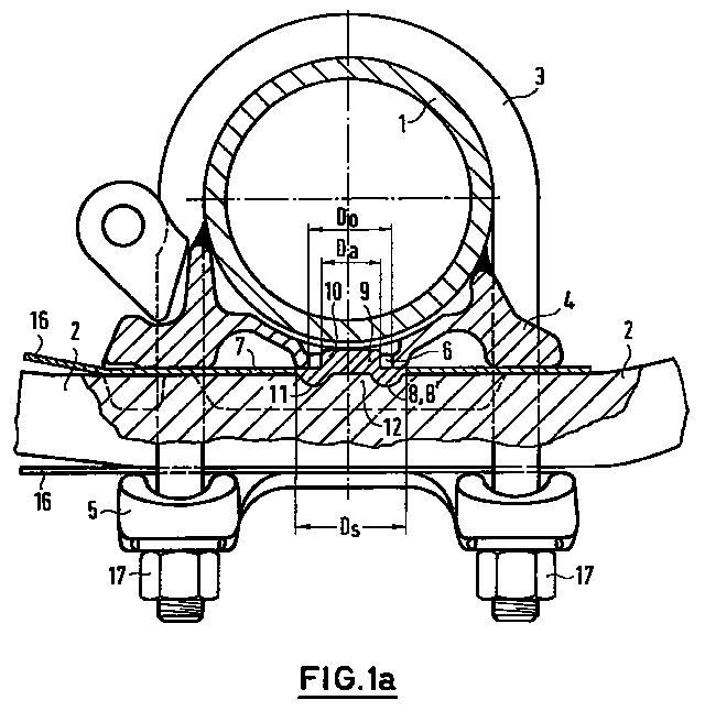
- the clamping of the axle body 1 shown in FIG. 1 Vehicle axle on a spring leaf or guide link 2 takes place by means of two parallel U-brackets 3, which around are guided around the axle body 1 and with their respective both ends laterally on the spring leaf or guide link 2 passed and a screw at its free ends 17 have.
- the clamping of the axle body 1 takes place between an axle flap welded to the axle body 1 4, which is on top of the spring leaf or the guide link 2 supports and one from below on the spring leaf or Guide arm 2 adjacent clamping plate 5.
- the case is also a galvanized one Strap 16 included for corrosion protection reasons, which at the front end of the spring leaf or the guide link 2 whose pivot point is led around.
- a trough-shaped rounded can also be used continuous recess 8 may be provided, in which the shown push block 9 engages with the annular bead 11 or alternatively another thrust block 9 with a mushroom head Surface contour instead of the ring bead 11.
- the combination Ring groove / bead 8 ', 11 has the advantage, however, that more horizontal contact surface in the event of an impending axis shift is available.
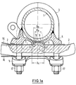
- FIG. 1 a is a push block 9 used, which with respect to the diameter Da in Fig. 2b corresponds to the push block shown. It is also possible to use a push block 9 according to FIG. 2a, the cone-shaped projection 10, the opening 6 of the axle flap 4 in Cross section completely filled.
- the spring leaf or the guide link 2 only on its upper surface 7 a Well 8, 8 '.
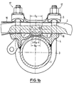
- the spring leaf or the guide link 1b has only on its lower surface 7 a recess 8 in the form of an annular groove 8 'corresponding to FIG. 1a. Otherwise, the clamping is with that in Fig. 1a illustrated identical. But it is also possible that Spring leaf or the guide arm 2 (also) on his or its other surface with such a depression 8, 8 'so that one and the same spring leaf or one and the same control arm 2 without rotation both at a clamping according to FIG. 1a as well as a clamping 1b can be used.
- Push blocks 9 each have an end recess 15 in the Neck 10 area to save material.
- the cone-shaped approach 10 of the Push block 9 has a preferred diameter Ds of between 30 and 45 mm, in particular about 35 mm.
- the diameter Ds of the essentially circular disk-shaped thrust block 9 is between 50 and 60 mm, preferably about 55 mm.
- the Outer diameter Dk of the surface contour, in particular the Ring bead 11 of the thrust block 9 is larger than that Outside diameter Since the approach 10 of the thrust block 9 and in particular, slightly larger than the diameter of the Opening 6 in the axle lobe 4.
- the outer diameter Ds of the Push block 9 is in turn slightly larger than that Outside diameter of the annular bead 8, 8 '.
Landscapes
- Engineering & Computer Science (AREA)
- Mechanical Engineering (AREA)
- Vehicle Body Suspensions (AREA)
- Snaps, Bayonet Connections, Set Pins, And Snap Rings (AREA)
- Steering-Linkage Mechanisms And Four-Wheel Steering (AREA)
- Automobile Manufacture Line, Endless Track Vehicle, Trailer (AREA)
- Springs (AREA)
Abstract
Description
- Fig. 1a
- eine die Erfindung aufweisende Einspannung, teilweise senkrecht zur geometrischen Achse des Achskörpers geschnitten,
- Fig. 1b
- eine erfindungsgemäße Ausführung gemäß Fig. 1a, wobei jedoch der Achskörper unterhalb des Federblattes bzw. Führungslenkers eingespannt ist,
- Fig.2a und 2b
- im Schnitt zwei unterschiedliche Ausführungsformen eines erfindungsgemäßen Schubklotzes, welche sich im wesentlichen in dem Durchmesser des Ansatzes voneinander unterscheiden, und
- Fig. 3
- eine vergrößerte Ausschnittsdarstellung einer Einspannung ähnlich der in Fig. 1a im Bereich des Schubklotzes.
- 1.
- Achskörper
- 2
- Federblatt bzw. Führungslenker
- 3
- U-Bügel
- 4
- Achslappen
- 5
- Spannplatte
- 6
- Öffnung
- 7
- Oberfläche
- 8
- Vertiefung
- 8'
- Ringnut
- 9
- Schubklotz
- 10
- Ansatz
- 11
- Ringwulst
- 12
- Zentrierkegel
- 13
- Oberfläche des Zentrierkegels
- 14
- Oberfläche des Schubklotzes
- 15
- Aussparung
- 16
- Fangblech
- 17
- Verschraubung
- Da
- Außendurchmesser Ansatz
- Dk
- Außendurchmesser Oberflächenkontur
- Do
- Durchmesser Öffnung
- Ds
- Durchmesser Schubklotz
- H
- Höhe
- T
- Tiefe
Claims (14)
- Einspannung für den Achskörper (1) einer Fahrzeugachse, bei welcher mindestens ein Federblatt oder mindestens ein Führungslenker (2) und der Achskörper (1), z.B. mittels eines U-Bügels (3) zwischen einem an dem Achskörper (1) angeschweißten Achslappen (4) und einer Spannplatte (5), zusammengespannt sind, sowie mit in eine Öffnung (6) des Achslappens (4) hineinragenden Mitteln zum Verhindern des Verschiebens des Achsköpers (1) auf dem Federblatt bzw. dem Führungslenker (2), dadurch gekennzeichnet, daß in der dem Achslappen (4) zugewandten Oberfläche (7) eine konkave Vertiefung (8) eingebracht und ein Schubklotz (9) mit passender konvexer Oberflächenkontur in die Vertiefung (8) eingelegt ist, wobei der Schubklotz (9) mit einem Ansatz (10) in die Öffnung (6) des Achslappens (4) hineinragt.
- Einspannung nach Anspruch 1, dadurch gekennzeichnet, daß die Vertiefung (8) eine Ringnut (8') mit konkavem Nutgrund ist und die Oberflächenkontur des Schubklotzes (9) einen dazu passenden Ringwulst (11) bildet.
- Einspannung nach Anspruch 1 oder 2, dadurch gekennzeichnet, daß der Ansatz (10) des Schubklotzes (9) mit radialem Spiel in die Öffnung (6) des Achslappens (4) hineinragt.
- Einspannung nach Anspruch 1 oder 2, dadurch gekennzeichnet, daß der zapfenförmige Ansatz (10) des Schubklotzes (9) die Öffnung (6) des Achszapfens (4) im Querschnitt vollständig ausfüllt.
- Einspannung nach einem der Ansprüche 1 bis 4, dadurch gekennzeichnet, daß Federblatt bzw. Führungslenker (2) beidseitig mit je einer konkaven Vertiefung (8, 8') versehen ist.
- Einspannung nach einem der Ansprüche 1 bis 5, dadurch gekennzeichnet, daß die Vertiefung (8, 8') vor der Endbehandlung des Federblattes bzw. des Führungslenkers (2) eingedrückt oder eingefräst ist.
- Einspannung nach einem der Ansprüche 1 bis 6, dadurch gekennzeichnet, daß die Vertiefung (8, 8') eine Tiefe (T)(und dementsprechend die Oberflächenkontur des Schubklotzes (9) eine Höhe (H)) von zwischen 3 und 8 mm, vorzugsweise etwa 5 mm, hat.
- Einspannung nach einem der Ansprüche 1 bis 7, dadurch gekennzeichnet, daß der Ansatz (10) des Schubklotzes (9) zapfenförmig mit einem Durchmesser (Ds) von zwischen 30 und 45 mm, vorzugsweise etwa 35 mm, ausgebildet ist.
- Einspannung nach einem der Ansprüche 1 bis 8, dadurch gekennzeichnet, daß der Ansatz (10) des Schubklotzes (9) in der Öffnung (6) des Achslappens (4) ein radiales Spiel von zwischen 6 und 12 mm, vorzugsweise etwa 10 mm, hat.
- Einspannung nach einem der Ansprüche 1 bis 9, dadurch gekennzeichnet, daß der Schubklotz (9) kreisscheibenförmig mit einem Durchmesser (Ds) von zwischen 50 und 60 mm, vorzugsweise etwa 55 mm, ausgebildet ist.
- Einspannung nach einem der Ansprüche 1 bis 10, dadurch gekennzeichnet, daß der Außendurchmesser (Dv) der Vertiefung (8, 8') und damit auch der in sie eingreifenden Oberflächenkontur des Schubklotzes (9), insbesondere des Ringwulstes (11), in der Größenordnung des Durchmessers (Do) der Öffnung (6) des Achslappens (4) liegt.
- Einspannung nach einem der Ansprüche 1 bis 11, dadurch gekennzeichnet, daß die Oberflächenkontur, insbesondere der Ringwulst (11), des Schubklotzes (9) einen Außendurchmesser (Dk) hat, welcher größer als der Außendurchmesser (Da) des Ansatzes (10) des Schubklotzes (9) ist.
- Einspannung nach einem der Ansprüche 1 bis 12, dadurch gekennzeichnet, daß der Oberflächenbereich des Federblattes bzw. des Führungslenkers (2) innerhalb der Ringnut (8') einen Zentrierkegelstumpf (12) bildet, dessen Oberfläche (13) einen Spalt zu der gegenüberliegenden Oberfläche (14) des Schubklotzes (9) innerhalb des Ringwulstes (11) hat.
- Einspannung nach einem der Ansprüche 1 bis 13, dadurch gekennzeichnet, daß in dem Ansatz (10) des Schubklotzes (9) stirnseitig eine Aussparung (15) vorgesehen ist.
Applications Claiming Priority (2)
| Application Number | Priority Date | Filing Date | Title |
|---|---|---|---|
| DE29616351U | 1996-09-19 | ||
| DE29616351U DE29616351U1 (de) | 1996-09-19 | 1996-09-19 | Einspannung für den Achskörper einer Fahrzeugachse |
Publications (3)
| Publication Number | Publication Date |
|---|---|
| EP0830957A2 true EP0830957A2 (de) | 1998-03-25 |
| EP0830957A3 EP0830957A3 (de) | 2000-12-06 |
| EP0830957B1 EP0830957B1 (de) | 2003-07-30 |
Family
ID=8029453
Family Applications (1)
| Application Number | Title | Priority Date | Filing Date |
|---|---|---|---|
| EP97108366A Expired - Lifetime EP0830957B1 (de) | 1996-09-19 | 1997-05-23 | Einspannung für den Achskörper einer Fahrzeugachse |
Country Status (3)
| Country | Link |
|---|---|
| EP (1) | EP0830957B1 (de) |
| DE (2) | DE29616351U1 (de) |
| ES (1) | ES2203736T3 (de) |
Cited By (14)
| Publication number | Priority date | Publication date | Assignee | Title |
|---|---|---|---|---|
| NL1013173C2 (nl) * | 1999-09-29 | 2001-03-30 | Weweler Nv | Verbinding tussen een wielas van een voertuig en een de wielas dragende draagarm. |
| EP1088687A1 (de) * | 1999-09-29 | 2001-04-04 | Weweler Nederland B.V. | Verbindung zwischen einer Radachse eines Fahrzeugs und einem die Radachse tragenden Tragarm |
| NL1015231C2 (nl) * | 2000-05-18 | 2001-11-20 | Weweler Nv | Verbinding tussen voertuigas en draagarm. |
| EP1273464A1 (de) | 2001-07-02 | 2003-01-08 | Weweler Nederland B.V. | Verbindung zwischen einer starren Radachse eines Fahrzeugs und einem die Radachse tragenden Tragarm |
| NL1019766C2 (nl) * | 2002-01-17 | 2003-07-18 | Schmitz Cargobull Ag | Verbinding tussen voertuigas en draagarm. |
| EP1508459A1 (de) | 2003-08-19 | 2005-02-23 | Weweler Nederland B.V. | Verbindungselement zwischen einer Rundprofil-Fahrzeugachse und einem Aufhängungslenker |
| NL2008050C2 (en) * | 2011-12-28 | 2013-07-01 | Vdl Weweler B V | Wheel axle suspension. |
| US8540262B2 (en) | 2010-02-25 | 2013-09-24 | Man Truck & Bus Ag | Commercial vehicle and device for attaching a spring element to a commercial vehicle axle |
| DE102012207157A1 (de) * | 2012-04-30 | 2013-10-31 | Saf-Holland Gmbh | Achsanbindung |
| WO2013181195A1 (en) * | 2012-05-30 | 2013-12-05 | Hendrickson Usa, L.L.C. | Energy storing suspension components having retention recesses |
| US8820760B2 (en) | 2011-12-28 | 2014-09-02 | Vdl Weweler B.V. | Wheel axle suspension |
| WO2014207191A1 (de) * | 2013-06-28 | 2014-12-31 | Saf-Holland Gmbh | Schale |
| US20210245564A1 (en) * | 2018-06-06 | 2021-08-12 | Saf-Holland Gmbh | Axle mounting unit |
| EP3717286B1 (de) | 2017-11-28 | 2022-04-13 | VDL Weweler B.V. | Achsenklemmanordnung |
Families Citing this family (4)
| Publication number | Priority date | Publication date | Assignee | Title |
|---|---|---|---|---|
| DE29713996U1 (de) * | 1997-08-06 | 1998-12-10 | Trenkamp & Gehle GmbH, 49413 Dinklage | Vorrichtung zur Verbindung des Achskörpers einer Radachse, insbesondere eines Nutzfahrzeugs, mit den Längslenkern einer Achsabstützung |
| WO2012078031A1 (en) * | 2010-12-09 | 2012-06-14 | Vdl Weweler B.V. | Vehicle axle suspension, and vehicle comprising such vehicle axle suspension |
| DE102013008877A1 (de) * | 2013-05-27 | 2014-11-27 | Schomäcker Federnwerk GmbH | Parabellenker |
| DE102016006641A1 (de) * | 2016-06-02 | 2017-12-07 | Daimler Ag | Blattfeder für ein Fahrzeug |
Family Cites Families (6)
| Publication number | Priority date | Publication date | Assignee | Title |
|---|---|---|---|---|
| US1379798A (en) * | 1920-04-12 | 1921-05-31 | Earl F Burgess | Vehicle-spring-retaining means |
| US3437333A (en) * | 1966-10-24 | 1969-04-08 | North American Rockwell | Spring seat |
| DE6608349U (de) * | 1968-05-10 | 1971-08-26 | Brueninghaus Gmbh Stahlwerke | Mittenbefestigung fuer federblaetter. |
| US3964735A (en) * | 1975-03-03 | 1976-06-22 | Wright Oliver L | Torsion bar adaptor for vehicle springs |
| GB8315704D0 (en) * | 1983-06-08 | 1983-07-13 | Gkn Technology Ltd | Securing components to springs of composite material |
| CA2078014A1 (en) * | 1991-09-18 | 1993-03-19 | Donald L. Stephens | Lightweight suspension system for a wheeled vehicle, spring arm and method of manufacture |
-
1996
- 1996-09-19 DE DE29616351U patent/DE29616351U1/de not_active Expired - Lifetime
-
1997
- 1997-05-23 EP EP97108366A patent/EP0830957B1/de not_active Expired - Lifetime
- 1997-05-23 DE DE59710501T patent/DE59710501D1/de not_active Expired - Lifetime
- 1997-05-23 ES ES97108366T patent/ES2203736T3/es not_active Expired - Lifetime
Cited By (23)
| Publication number | Priority date | Publication date | Assignee | Title |
|---|---|---|---|---|
| NL1013173C2 (nl) * | 1999-09-29 | 2001-03-30 | Weweler Nv | Verbinding tussen een wielas van een voertuig en een de wielas dragende draagarm. |
| EP1088687A1 (de) * | 1999-09-29 | 2001-04-04 | Weweler Nederland B.V. | Verbindung zwischen einer Radachse eines Fahrzeugs und einem die Radachse tragenden Tragarm |
| NL1015231C2 (nl) * | 2000-05-18 | 2001-11-20 | Weweler Nv | Verbinding tussen voertuigas en draagarm. |
| EP1155883A1 (de) * | 2000-05-18 | 2001-11-21 | Weweler Nederland N.V. | Verbindung zwischen einer Fahrzeugradachse und einem Aufhängungslenker |
| EP1273464A1 (de) | 2001-07-02 | 2003-01-08 | Weweler Nederland B.V. | Verbindung zwischen einer starren Radachse eines Fahrzeugs und einem die Radachse tragenden Tragarm |
| NL1018435C2 (nl) | 2001-07-02 | 2003-01-13 | Weweler Nv | Verbinding tussen een aslichaam van een wielas van een voertuig en een de wielas dragende draagarm. |
| NL1019766C2 (nl) * | 2002-01-17 | 2003-07-18 | Schmitz Cargobull Ag | Verbinding tussen voertuigas en draagarm. |
| EP1334848A1 (de) * | 2002-01-17 | 2003-08-13 | Schmitz Cargobull AG | Fahrzeugachsenelement mit Tragarm und damit verbundenem Achsrohr |
| EP1508459A1 (de) | 2003-08-19 | 2005-02-23 | Weweler Nederland B.V. | Verbindungselement zwischen einer Rundprofil-Fahrzeugachse und einem Aufhängungslenker |
| US8540262B2 (en) | 2010-02-25 | 2013-09-24 | Man Truck & Bus Ag | Commercial vehicle and device for attaching a spring element to a commercial vehicle axle |
| US8820760B2 (en) | 2011-12-28 | 2014-09-02 | Vdl Weweler B.V. | Wheel axle suspension |
| NL2008050C2 (en) * | 2011-12-28 | 2013-07-01 | Vdl Weweler B V | Wheel axle suspension. |
| US10035377B2 (en) | 2012-04-30 | 2018-07-31 | Saf-Holland Gmbh | Axle attachment |
| DE102012207157A1 (de) * | 2012-04-30 | 2013-10-31 | Saf-Holland Gmbh | Achsanbindung |
| WO2013181195A1 (en) * | 2012-05-30 | 2013-12-05 | Hendrickson Usa, L.L.C. | Energy storing suspension components having retention recesses |
| US9050870B2 (en) | 2012-05-30 | 2015-06-09 | Hendrickson Usa, L.L.C. | Energy storing suspension components having retention recesses |
| US9415654B2 (en) | 2012-05-30 | 2016-08-16 | Hendrickson Usa, L.L.C. | Energy storing suspension components having retention recesses |
| US9796231B2 (en) | 2012-05-30 | 2017-10-24 | Hendrickson Usa, L.L.C. | Energy storing suspension components having retention recesses |
| WO2014207191A1 (de) * | 2013-06-28 | 2014-12-31 | Saf-Holland Gmbh | Schale |
| RU2623343C1 (ru) * | 2013-06-28 | 2017-06-23 | Саф-Холланд Гмбх | Оболочка |
| EP3717286B1 (de) | 2017-11-28 | 2022-04-13 | VDL Weweler B.V. | Achsenklemmanordnung |
| US20210245564A1 (en) * | 2018-06-06 | 2021-08-12 | Saf-Holland Gmbh | Axle mounting unit |
| US11623488B2 (en) * | 2018-06-06 | 2023-04-11 | Saf-Holland Gmbh | Axle mounting unit |
Also Published As
| Publication number | Publication date |
|---|---|
| DE59710501D1 (de) | 2003-09-04 |
| ES2203736T3 (es) | 2004-04-16 |
| DE29616351U1 (de) | 1996-11-14 |
| EP0830957A3 (de) | 2000-12-06 |
| EP0830957B1 (de) | 2003-07-30 |
Similar Documents
| Publication | Publication Date | Title |
|---|---|---|
| EP0830957A2 (de) | Einspannung für den Achskörper einer Fahrzeugachse | |
| EP0937311B1 (de) | Vorrichtung zur befestigung eines entfernungssensors an einem kraftfahrzeug | |
| EP0420882B2 (de) | Schiene für schienenfahrzeuge | |
| DE69303670T2 (de) | Kugelbefestigung für Fahrzeugscheinwerferreflektor | |
| CH618252A5 (de) | ||
| EP3698056A1 (de) | Toleranzausgleichsanordnung | |
| DE29616631U1 (de) | Befestigungsanordnung | |
| DE102004053803A1 (de) | Gewindefurchende Schraube | |
| DE2708538C3 (de) | Verbindung zwischen den Kettengliedern einer Gleiskette | |
| EP1088687A1 (de) | Verbindung zwischen einer Radachse eines Fahrzeugs und einem die Radachse tragenden Tragarm | |
| CH616892A5 (en) | Track for a track laying vehicle | |
| DE19748117C2 (de) | Kugelzapfen | |
| DE69701947T2 (de) | Aufhängung von Auspuffanlagen | |
| DE69006308T2 (de) | Stütz- und Verankerungsvorrichtung für vorgefertigte, insbesondere aus Beton oder ähnlichem hergestellte Gebäudeteile. | |
| DE69514215T2 (de) | Spielfreie Zugstangenanordnung für einen Güterwagon | |
| DE19735753A1 (de) | Drehstabanordnung | |
| DE29800079U1 (de) | Auf der Felge eines Kraftfahrzeugrades verspannbarer Notlaufeinsatz | |
| EP0167991A2 (de) | Gelenkkopfanordnung zum gelenkigen und jederzeit lösbaren Verbinden einer Spreize mit einer Verbauwand eines Verbaus | |
| DE10007454C2 (de) | Toleranzausgleich-Element | |
| DE102006001521B4 (de) | Vorrichtung zum exakten Positionieren einer Leuchte an der Karosserie eines Fahrzeuges | |
| DE69528215T2 (de) | Befestigungsvorrichtung für mindestens zwei Bauteile, z. B. Fahrzeugkarosserie | |
| DE69216352T2 (de) | Befestigung eines Vorratsbehälters | |
| EP1335144A1 (de) | Bremsträgeranordnung | |
| EP4256209B1 (de) | System zur befestigung einer schiene und verfahren zur reparatur | |
| DE19636186C2 (de) | Manuell längenveränderliche Zugvorrichtung für mehrachsige Anhänger |
Legal Events
| Date | Code | Title | Description |
|---|---|---|---|
| PUAI | Public reference made under article 153(3) epc to a published international application that has entered the european phase |
Free format text: ORIGINAL CODE: 0009012 |
|
| AK | Designated contracting states |
Kind code of ref document: A2 Designated state(s): DE ES FR GB IT |
|
| AX | Request for extension of the european patent |
Free format text: AL;LT;LV;RO;SI |
|
| PUAL | Search report despatched |
Free format text: ORIGINAL CODE: 0009013 |
|
| AK | Designated contracting states |
Kind code of ref document: A3 Designated state(s): AT BE CH DE DK ES FI FR GB GR IE IT LI LU MC NL PT SE |
|
| AX | Request for extension of the european patent |
Free format text: AL;LT;LV;RO;SI |
|
| 17P | Request for examination filed |
Effective date: 20010515 |
|
| AKX | Designation fees paid |
Free format text: DE ES FR GB IT |
|
| 17Q | First examination report despatched |
Effective date: 20010924 |
|
| GRAH | Despatch of communication of intention to grant a patent |
Free format text: ORIGINAL CODE: EPIDOS IGRA |
|
| GRAH | Despatch of communication of intention to grant a patent |
Free format text: ORIGINAL CODE: EPIDOS IGRA |
|
| GRAA | (expected) grant |
Free format text: ORIGINAL CODE: 0009210 |
|
| AK | Designated contracting states |
Designated state(s): DE ES FR GB IT |
|
| REG | Reference to a national code |
Ref country code: GB Ref legal event code: FG4D Free format text: NOT ENGLISH |
|
| REF | Corresponds to: |
Ref document number: 59710501 Country of ref document: DE Date of ref document: 20030904 Kind code of ref document: P |
|
| GBT | Gb: translation of ep patent filed (gb section 77(6)(a)/1977) | ||
| REG | Reference to a national code |
Ref country code: ES Ref legal event code: FG2A Ref document number: 2203736 Country of ref document: ES Kind code of ref document: T3 |
|
| ET | Fr: translation filed | ||
| PLBE | No opposition filed within time limit |
Free format text: ORIGINAL CODE: 0009261 |
|
| STAA | Information on the status of an ep patent application or granted ep patent |
Free format text: STATUS: NO OPPOSITION FILED WITHIN TIME LIMIT |
|
| 26N | No opposition filed |
Effective date: 20040504 |
|
| REG | Reference to a national code |
Ref country code: FR Ref legal event code: CD Owner name: SAF-HOLLAND GMBH, DE Effective date: 20121015 Ref country code: FR Ref legal event code: CA Effective date: 20121015 |
|
| REG | Reference to a national code |
Ref country code: FR Ref legal event code: PLFP Year of fee payment: 20 |
|
| PGFP | Annual fee paid to national office [announced via postgrant information from national office to epo] |
Ref country code: GB Payment date: 20160523 Year of fee payment: 20 Ref country code: DE Payment date: 20160420 Year of fee payment: 20 Ref country code: ES Payment date: 20160523 Year of fee payment: 20 |
|
| PGFP | Annual fee paid to national office [announced via postgrant information from national office to epo] |
Ref country code: FR Payment date: 20160523 Year of fee payment: 20 Ref country code: IT Payment date: 20160524 Year of fee payment: 20 |
|
| REG | Reference to a national code |
Ref country code: DE Ref legal event code: R071 Ref document number: 59710501 Country of ref document: DE |
|
| REG | Reference to a national code |
Ref country code: GB Ref legal event code: PE20 Expiry date: 20170522 |
|
| PG25 | Lapsed in a contracting state [announced via postgrant information from national office to epo] |
Ref country code: GB Free format text: LAPSE BECAUSE OF EXPIRATION OF PROTECTION Effective date: 20170522 |
|
| REG | Reference to a national code |
Ref country code: ES Ref legal event code: FD2A Effective date: 20170830 |
|
| PG25 | Lapsed in a contracting state [announced via postgrant information from national office to epo] |
Ref country code: ES Free format text: LAPSE BECAUSE OF EXPIRATION OF PROTECTION Effective date: 20170524 |