EP0829678B1 - Kanalbrenner und Verfahren zum Aufheizen eines strömenden Gases - Google Patents
Kanalbrenner und Verfahren zum Aufheizen eines strömenden Gases Download PDFInfo
- Publication number
- EP0829678B1 EP0829678B1 EP97112806A EP97112806A EP0829678B1 EP 0829678 B1 EP0829678 B1 EP 0829678B1 EP 97112806 A EP97112806 A EP 97112806A EP 97112806 A EP97112806 A EP 97112806A EP 0829678 B1 EP0829678 B1 EP 0829678B1
- Authority
- EP
- European Patent Office
- Prior art keywords
- combustion chamber
- gas
- air
- slot
- side walls
- Prior art date
- Legal status (The legal status is an assumption and is not a legal conclusion. Google has not performed a legal analysis and makes no representation as to the accuracy of the status listed.)
- Expired - Lifetime
Links
- 238000010438 heat treatment Methods 0.000 title claims description 6
- 238000000034 method Methods 0.000 title claims description 4
- 238000002485 combustion reaction Methods 0.000 claims abstract description 62
- 239000007789 gas Substances 0.000 claims abstract description 59
- 239000000567 combustion gas Substances 0.000 claims description 7
- 238000005192 partition Methods 0.000 claims description 5
- 239000002737 fuel gas Substances 0.000 abstract description 12
- MWUXSHHQAYIFBG-UHFFFAOYSA-N nitrogen oxide Inorganic materials O=[N] MWUXSHHQAYIFBG-UHFFFAOYSA-N 0.000 description 9
- 230000015572 biosynthetic process Effects 0.000 description 3
- UGFAIRIUMAVXCW-UHFFFAOYSA-N Carbon monoxide Chemical compound [O+]#[C-] UGFAIRIUMAVXCW-UHFFFAOYSA-N 0.000 description 2
- QVGXLLKOCUKJST-UHFFFAOYSA-N atomic oxygen Chemical compound [O] QVGXLLKOCUKJST-UHFFFAOYSA-N 0.000 description 2
- 239000003546 flue gas Substances 0.000 description 2
- VNWKTOKETHGBQD-UHFFFAOYSA-N methane Chemical compound C VNWKTOKETHGBQD-UHFFFAOYSA-N 0.000 description 2
- 238000012544 monitoring process Methods 0.000 description 2
- 239000001301 oxygen Substances 0.000 description 2
- 229910052760 oxygen Inorganic materials 0.000 description 2
- XLYOFNOQVPJJNP-UHFFFAOYSA-N water Chemical compound O XLYOFNOQVPJJNP-UHFFFAOYSA-N 0.000 description 2
- 238000007664 blowing Methods 0.000 description 1
- 238000004140 cleaning Methods 0.000 description 1
- 239000000571 coke Substances 0.000 description 1
- 230000003111 delayed effect Effects 0.000 description 1
- 230000001419 dependent effect Effects 0.000 description 1
- 238000001035 drying Methods 0.000 description 1
- 230000002349 favourable effect Effects 0.000 description 1
- 239000000446 fuel Substances 0.000 description 1
- 239000001257 hydrogen Substances 0.000 description 1
- 229910052739 hydrogen Inorganic materials 0.000 description 1
- 125000004435 hydrogen atom Chemical class [H]* 0.000 description 1
- 239000003345 natural gas Substances 0.000 description 1
- 230000001629 suppression Effects 0.000 description 1
Images



Classifications
-
- F—MECHANICAL ENGINEERING; LIGHTING; HEATING; WEAPONS; BLASTING
- F23—COMBUSTION APPARATUS; COMBUSTION PROCESSES
- F23D—BURNERS
- F23D14/00—Burners for combustion of a gas, e.g. of a gas stored under pressure as a liquid
- F23D14/20—Non-premix gas burners, i.e. in which gaseous fuel is mixed with combustion air on arrival at the combustion zone
-
- F—MECHANICAL ENGINEERING; LIGHTING; HEATING; WEAPONS; BLASTING
- F24—HEATING; RANGES; VENTILATING
- F24H—FLUID HEATERS, e.g. WATER OR AIR HEATERS, HAVING HEAT-GENERATING MEANS, e.g. HEAT PUMPS, IN GENERAL
- F24H3/00—Air heaters
- F24H3/02—Air heaters with forced circulation
- F24H3/04—Air heaters with forced circulation the air being in direct contact with the heating medium, e.g. electric heating element
- F24H3/0488—Air heaters with forced circulation the air being in direct contact with the heating medium, e.g. electric heating element using fluid fuel
-
- F—MECHANICAL ENGINEERING; LIGHTING; HEATING; WEAPONS; BLASTING
- F23—COMBUSTION APPARATUS; COMBUSTION PROCESSES
- F23C—METHODS OR APPARATUS FOR COMBUSTION USING FLUID FUEL OR SOLID FUEL SUSPENDED IN A CARRIER GAS OR AIR
- F23C2202/00—Fluegas recirculation
- F23C2202/40—Inducing local whirls around flame
-
- F—MECHANICAL ENGINEERING; LIGHTING; HEATING; WEAPONS; BLASTING
- F23—COMBUSTION APPARATUS; COMBUSTION PROCESSES
- F23C—METHODS OR APPARATUS FOR COMBUSTION USING FLUID FUEL OR SOLID FUEL SUSPENDED IN A CARRIER GAS OR AIR
- F23C2203/00—Flame cooling methods otherwise than by staging or recirculation
- F23C2203/30—Injection of tempering fluids
-
- F—MECHANICAL ENGINEERING; LIGHTING; HEATING; WEAPONS; BLASTING
- F23—COMBUSTION APPARATUS; COMBUSTION PROCESSES
- F23D—BURNERS
- F23D2900/00—Special features of, or arrangements for burners using fluid fuels or solid fuels suspended in a carrier gas
- F23D2900/21—Burners specially adapted for a particular use
- F23D2900/21003—Burners specially adapted for a particular use for heating or re-burning air or gas in a duct
-
- Y—GENERAL TAGGING OF NEW TECHNOLOGICAL DEVELOPMENTS; GENERAL TAGGING OF CROSS-SECTIONAL TECHNOLOGIES SPANNING OVER SEVERAL SECTIONS OF THE IPC; TECHNICAL SUBJECTS COVERED BY FORMER USPC CROSS-REFERENCE ART COLLECTIONS [XRACs] AND DIGESTS
- Y02—TECHNOLOGIES OR APPLICATIONS FOR MITIGATION OR ADAPTATION AGAINST CLIMATE CHANGE
- Y02B—CLIMATE CHANGE MITIGATION TECHNOLOGIES RELATED TO BUILDINGS, e.g. HOUSING, HOUSE APPLIANCES OR RELATED END-USER APPLICATIONS
- Y02B30/00—Energy efficient heating, ventilation or air conditioning [HVAC]
Definitions
- the burner base 5 take different forms.
- the side walls 4 of the Combustion chamber 3 facing part of the burner base 5 can, like shown to the right of the burner longitudinal axis, towards air box 2 convex or, as shown on the left of the longitudinal axis of the burner, just be trained.
- the flat bottom part can be vertical (Fig. 7) or inclined (Fig. 2) to the longitudinal axis of the burner.
Landscapes
- Engineering & Computer Science (AREA)
- Chemical & Material Sciences (AREA)
- Combustion & Propulsion (AREA)
- Mechanical Engineering (AREA)
- General Engineering & Computer Science (AREA)
- Physics & Mathematics (AREA)
- Thermal Sciences (AREA)
- Gas Burners (AREA)
- Combustion Of Fluid Fuel (AREA)
- Pre-Mixing And Non-Premixing Gas Burner (AREA)
Description
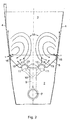
- Fig. 1
- einen Längsschnitt durch einen Strömungskanal mit einem Kanalbrenner,
- Fig. 2
- den Schnitt II-II nach Fig. 1 im vergrößerten Maßstab,
- Fig. 3 bis 8
- den Schnitt II-II nach Fig. 1 für unterschiedliche Ausführungsformen eines Einzelbrenners des Kanalbrenners.
| Sauerstoffgehalt | 0 bis 21 Vol.% |
| Wasserdampfgehalt | 0 bis 40 Vol.% |
| Temperatur | -50 bis 700 °C |
Claims (16)
- Kanalbrenner zum Aufheizen eines strömenden Gases, der innerhalb eines das Gas führenden Kanals (1) angeordnet und mit einem Luftkasten (2) und einem Brennraum (3) versehen ist, die durch einen Brennerboden (5) voneinander getrennt sind, wobei der Luftkasten (2) mit einer Luftzuführung (6) verbunden, und der Brennerboden (5) mit Luftdurchtrittsöffnungen versehen ist, die als Schlitze (15) ausgebildet und nahe einer Seitenwand (4) des Brennraumes (3) angeordnet sind, wobei durch den Luftkasten (2) ein Gasführungsrohr (7) geführt ist, das mit einer oder mehreren Gasdüsen (12) verbunden ist, die mit in den Brennraum (3) mündenden Düsenbohrungen (13) versehen sind, wobei der Austrittsquerschnitt der Schlitze (15) seitlich von den Düsenbohrungen (13) der Gasdüsen (12) vorgesehen ist, dadurch gekennzeichnet, daß der Austrittsquerschnitt der Schlitze (15) in Strömungsrichtung des in den Brennraum (3) eingeleiteten Brenngases in einem Abstand hinter den Düsenbohrungen (13) der Gasdüsen (12) sich befindet, daß sich die Schlitze (15) in eine Richtung parallel zu den Seitenwänden (4) des Brennraumes (3) erstrecken und daß das Verhältnis der Breite s der Schlitze (15) zu der Breite 1 des Brennraumes (3) in Höhe des Austrittsquerschnittes der Schlitze (15) 0,01 bis 0,1 zu 1 beträgt, wobei beiderseits der Längsmittelebene des Brennraumes (3) Innenwirbel gebildet werden, in die sich die aus den Gasdüsen (12) austretenden Brenngasstrahlen so einmischen, daß die Innenwirbel im Vergleich mit der eingeblasenen Luft eine geringere Luftzahl aufweisen.
- Kanalbrenner nach Anspruch 1, dadurch gekennzeichnet, daß der Brennraum (3) mit Seitenwänden (4) versehen ist, die sich in Strömungsrichtung des in den Brennraum (3) eingeleiteten Gases konisch erweitern.
- Kanalbrenner nach Anspruch 1, dadurch gekennzeichnet, daß der Brennraum (3) mit parallelen Seitenwänden (4) versehen ist.
- Kanalbrenner nach einem der Ansprüche 1 bis 3, dadurch gekennzeichnet, daß die Seitenwänden (4) des Brennraumes (3) mit einer Einschnürung (17) versehen sind und daß die Breite 11 des Brennraumes (3) in Höhe der Einschnürung (17) zu der Breite l des Brennraumes (3) in Höhe des Austrittsquerschnittes des Schlitzes (15) bei parallelen Seitenwänden (4) 0,6 bis 0,9 und bei sich diffusorartig öffnenden Seitenwänden (4) 0,9 bis 1,25 zu 1 beträgt.
- Kanalbrenner nach einem der Ansprüche 1 bis 4, dadurch gekennzeichnet, daß der Schlitz (15) auf seiner Außenseite jeweils durch eine der Seitenwände (4) des Brennraumes (3) begrenzt ist.
- Kanalbrenner nach einem der Ansprüche 1 bis 4, dadurch gekennzeichnet, daß der Schlitz (15) in dem Brennerboden (5) angeordnet ist.
- Kanalbrenner nach einem der Ansprüche 1 bis 6, dadurch gekennzeichnet, daß sich der Schlitz (15) nach außen in Richtung auf die Seitenwände (4) des Brennraumes (3) erstreckt.
- Kanalbrenner nach einem der Ansprüche 1 bis 7, dadurch gekennzeichnet, daß in dem Schlitz (15) quer zu dessen Längserstreckung Bleche (25) angeordnet sind, die in Richtung der Brennerlängsachse (A) verlaufen.
- Kanalbrenner nach einem der Ansprüche 1 bis 7, dadurch gekennzeichnet, daß in dem wandnahen Bereich des Brennnraumes (3) oberhalb des Austrittsquerschnittes der Schlitze (15) Bleche (25) angeordnet sind, die in Richtung der Brennerlängsachse (A) und quer zur Seitenwand (4) verlaufen.
- Kanalbrenner nach einem der Ansprüche 1 bis 9, dadurch gekennzeichnet, daß der Schlitz (15) durch eine oder mehrere, sich in Längsrichtung des Schlitzes (15) erstreckende Trennwände (16) in mehrere parallele Teilschlitze aufgeteilt ist.
- Kanalbrenner nach einem der Ansprüche 1 bis 10, dadurch gekennzeichnet, daß unter Bildung eines Luftraumes (21) in einem Abstand oberhalb des Brennerbodens (5) und unter Bildung jeweils eines Spaltes in einem Abstand von den Gasdüsen (12) eine Platte (20) angeordnet ist und daß der Luftraum (21) mit dem Luftkasten (2) in Verbindung steht.
- Kanalbrenner nach einem der Ansprüche 1 bis 11, dadurch gekennzeichnet, daß der den Seitenwänden (4) des Brennraums (3) benachbarte Teil des Brennerbodens (5) gewölbt ist.
- Kanalbrenner nach einem der Ansprüche 1 bis 11, dadurch gekennzeichnet, daß der den Seitenwänden (4) des Brennraums (3) benachbarte Teil des Brennerbodens (5) eben ist und geneigt oder senkrecht zu der Längsachse des Kanalbrenners verläuft.
- Kanalbrenner nach einem der Ansprüche 1 bis 13, dadurch gekennzeichnet, daß außen an dem Luftkasten (2) oder den Seitenwänden (4) des Brennraumes (3) schräg in Strömungsrichtung des aufzuheizenden Gases angestellte, von außen verstellbare Flügel (22) angebracht sind.
- Kanalbrenner nach einem der Ansprüche 1 bis 14, dadurch gekennzeichnet, daß innerhalb des Luftkastens (2) Dampf führende Dampfrohre (23) angeordnet sind, die mit Austrittsbohrungen versehen sind, deren Achse (24) auf den Eintrittsquerschnitt des Schlitzes (15) gerichtet ist.
- Verfahren zum Aufheizen eines in einem Kanal (1) strömenden Gases unter Verwendung eines Kanalbrenners gemäß einem der Ansprüche 1 bis 15, dadurch gekennzeichnet, daß die Luft zur Verbrennung des Brenngases in einem Abstand von der Aufgabe des Brenngases längs und quer zur Strömungsrichtung des Brenngases derart aufgegeben wird, daß die Luft an der Seitenwand (4) entlang strömt und Innenwirbel (18) beiderseits der Längsmittelebene des Brennraumes (3) bildet, in die sich die aus den Gasdüsen (12) austretenden Brenngasstrahlen so einmischen, daß die Innenwirbel (18) im Vergleich mit der eingeblasenen Luft eine geringere Luftzahl aufweisen.
Applications Claiming Priority (2)
| Application Number | Priority Date | Filing Date | Title |
|---|---|---|---|
| DE19633004A DE19633004A1 (de) | 1996-08-16 | 1996-08-16 | Kanalbrenner und Verfahren zum Aufheizen eines strömenden Gases |
| DE19633004 | 1996-08-16 |
Publications (3)
| Publication Number | Publication Date |
|---|---|
| EP0829678A2 EP0829678A2 (de) | 1998-03-18 |
| EP0829678A3 EP0829678A3 (de) | 1999-03-10 |
| EP0829678B1 true EP0829678B1 (de) | 2001-09-26 |
Family
ID=7802773
Family Applications (1)
| Application Number | Title | Priority Date | Filing Date |
|---|---|---|---|
| EP97112806A Expired - Lifetime EP0829678B1 (de) | 1996-08-16 | 1997-07-25 | Kanalbrenner und Verfahren zum Aufheizen eines strömenden Gases |
Country Status (7)
| Country | Link |
|---|---|
| US (1) | US5820365A (de) |
| EP (1) | EP0829678B1 (de) |
| JP (1) | JPH1078202A (de) |
| CN (1) | CN1174308A (de) |
| AT (1) | ATE206195T1 (de) |
| DE (2) | DE19633004A1 (de) |
| DK (1) | DK0829678T3 (de) |
Families Citing this family (6)
| Publication number | Priority date | Publication date | Assignee | Title |
|---|---|---|---|---|
| US6468073B1 (en) * | 2001-06-12 | 2002-10-22 | Forney Corporation | Duct burner diffuser |
| AT413584B (de) * | 2003-08-01 | 2006-04-15 | Eisenbeiss Soehne Maschinen Un | Überlastkupplung |
| DE102011112781A1 (de) * | 2011-09-09 | 2013-03-14 | Thyssenkrupp Uhde Gmbh | Vorrichtung zur Bypass-Minderung in Ammoniak-Oxidationsbrennern |
| US9726372B2 (en) * | 2013-06-14 | 2017-08-08 | Beneq Oy | Burner nozzle, burner and a surface treatment device |
| CN105864814B (zh) * | 2016-05-25 | 2019-04-19 | 王科伟 | 高效旋流叠加式燃烧炉 |
| CN114294820A (zh) * | 2021-12-30 | 2022-04-08 | 李洪旭 | 一种家用燃气热水器 |
Family Cites Families (9)
| Publication number | Priority date | Publication date | Assignee | Title |
|---|---|---|---|---|
| FR1321385A (fr) * | 1962-05-09 | 1963-03-15 | Rolls Royce | Réchauffeur à combustion pour turbine à gaz ou analogue |
| FR1416121A (fr) * | 1964-11-24 | 1965-10-29 | Combustion Eng | Brûleur d'allumage |
| FR1438977A (fr) * | 1965-07-09 | 1966-05-13 | Schmitz & Apelt Industrieofenb | Réchauffeur d'air |
| US3649211A (en) * | 1970-02-05 | 1972-03-14 | Coen Co | Air augmented duct burner |
| DE2114817C3 (de) * | 1971-03-26 | 1975-02-27 | Klimatechnik Gmbh, 3203 Sarstedt | Gasbeheiztes Warmluftheizgerät |
| DE3066645D1 (en) | 1979-12-05 | 1984-03-22 | Nu Way Energy Ltd | An air-heating gas burner |
| US4737100A (en) * | 1986-04-30 | 1988-04-12 | John Zink Company | Duct burner apparatus |
| EP0352342B1 (de) | 1988-07-26 | 1992-02-12 | Maxon International N.V. | Brenner für Trocknungs- oder Gasreinigungsprozesse |
| US5131836A (en) * | 1991-02-06 | 1992-07-21 | Maxon Corporation | Line burner assembly |
-
1996
- 1996-08-16 DE DE19633004A patent/DE19633004A1/de not_active Withdrawn
-
1997
- 1997-07-16 JP JP9207137A patent/JPH1078202A/ja active Pending
- 1997-07-25 DK DK97112806T patent/DK0829678T3/da active
- 1997-07-25 EP EP97112806A patent/EP0829678B1/de not_active Expired - Lifetime
- 1997-07-25 US US08/900,652 patent/US5820365A/en not_active Expired - Fee Related
- 1997-07-25 AT AT97112806T patent/ATE206195T1/de not_active IP Right Cessation
- 1997-07-25 DE DE59704708T patent/DE59704708D1/de not_active Expired - Fee Related
- 1997-08-15 CN CN97115806A patent/CN1174308A/zh active Pending
Also Published As
| Publication number | Publication date |
|---|---|
| JPH1078202A (ja) | 1998-03-24 |
| US5820365A (en) | 1998-10-13 |
| CN1174308A (zh) | 1998-02-25 |
| ATE206195T1 (de) | 2001-10-15 |
| EP0829678A2 (de) | 1998-03-18 |
| DE59704708D1 (de) | 2001-10-31 |
| EP0829678A3 (de) | 1999-03-10 |
| DK0829678T3 (da) | 2002-01-21 |
| DE19633004A1 (de) | 1998-02-19 |
Similar Documents
| Publication | Publication Date | Title |
|---|---|---|
| DE69802736T2 (de) | Brenner für die Verbrennung von pulverförmigem Brennstoff | |
| DE60102991T2 (de) | Brenner mit geringen NOx Emissionen und Verfahren zum Verbrennen von flüssigen und gasförmigen Brennstoffen | |
| DE60318380T2 (de) | Festbrennstoffkessel und Betriebsverfahren einer Verbrennungsvorrichtung | |
| DE60011541T2 (de) | Verfahren und Vorrichtung zur NOx Reduktion | |
| DE2306537A1 (de) | Verminderung der bildung von no tief x bei der verbrennung von brennstoffen | |
| EP0139085A1 (de) | Verfahren und Brenner zum Verbrennen von flüssigen oder gasförmigen Brennstoffen unter verminderter Bildung von NOx | |
| DE3843543A1 (de) | Verfahren zum strahlvermischen von gasen | |
| DE2552374C2 (de) | Brenner für flüssigen oder gasförmigen Brennstoff | |
| CH678568A5 (de) | ||
| DE2738722A1 (de) | Verfahren und vorrichtung zur vermeidung der bildung von stickoxiden | |
| EP0742411B1 (de) | Luftzuströmung zu einer Vormischbrennkammer | |
| EP1130315B1 (de) | Atmosphärischer Gasbrenner | |
| DE3939197C3 (de) | Verfahren und Vorrichtung zur Minderung der Stickoxid-Konzentration im Abgasstrom von Verbrennungsprozessen | |
| DE19633004A1 (de) | Kanalbrenner und Verfahren zum Aufheizen eines strömenden Gases | |
| EP0777082A2 (de) | Vormischbrenner | |
| EP0352342B1 (de) | Brenner für Trocknungs- oder Gasreinigungsprozesse | |
| DE60018148T2 (de) | Brenner mit gestufter Luft- und Brennstoffzufuhr | |
| DE4402172A1 (de) | Verfahren zur Verbrennung von Brennstoff und Anlage zur Durchführung des Verfahrens | |
| EP0927320A1 (de) | Eckenbrenner für eine tangentialfeuerung und verfahren zu dessen betrieb | |
| DE69325502T2 (de) | Heizanlage für Räume | |
| DE19827936C1 (de) | Gasbrennersystem mit wenigstens zwei Brennerkörpern | |
| DE602004007569T2 (de) | Luftsystem für einen Wirbelbettkessel | |
| DE19704802A1 (de) | Vorrichtung und Verfahren zum Verbrennen von Brennstoff | |
| DE69527288T2 (de) | Feuerung mit Brenneranlage und Verbrennungsverfahren mit niedriger Stickstoffoxyderzeugung | |
| DE19541178C2 (de) | Verfahren zum Verbrennen von staubförmigem Brennstoff, insbesondere Braunkohle, in einem Feuerraum |
Legal Events
| Date | Code | Title | Description |
|---|---|---|---|
| PUAI | Public reference made under article 153(3) epc to a published international application that has entered the european phase |
Free format text: ORIGINAL CODE: 0009012 |
|
| AK | Designated contracting states |
Kind code of ref document: A2 Designated state(s): AT BE CH DE DK FR GB IT LI NL |
|
| AX | Request for extension of the european patent |
Free format text: AL;LT;LV;RO;SI |
|
| RAP1 | Party data changed (applicant data changed or rights of an application transferred) |
Owner name: BABCOCK KRAFTWERKSTECHNIK GMBH |
|
| PUAL | Search report despatched |
Free format text: ORIGINAL CODE: 0009013 |
|
| AK | Designated contracting states |
Kind code of ref document: A3 Designated state(s): AT BE CH DE DK ES FI FR GB GR IE IT LI LU MC NL PT SE |
|
| AX | Request for extension of the european patent |
Free format text: AL;LT;LV;RO;SI |
|
| 17P | Request for examination filed |
Effective date: 19990420 |
|
| AKX | Designation fees paid |
Free format text: AT BE CH DE DK FR GB IT LI NL |
|
| RAP1 | Party data changed (applicant data changed or rights of an application transferred) |
Owner name: BBP ENERGY GMBH |
|
| 17Q | First examination report despatched |
Effective date: 20000921 |
|
| GRAG | Despatch of communication of intention to grant |
Free format text: ORIGINAL CODE: EPIDOS AGRA |
|
| GRAG | Despatch of communication of intention to grant |
Free format text: ORIGINAL CODE: EPIDOS AGRA |
|
| GRAH | Despatch of communication of intention to grant a patent |
Free format text: ORIGINAL CODE: EPIDOS IGRA |
|
| GRAH | Despatch of communication of intention to grant a patent |
Free format text: ORIGINAL CODE: EPIDOS IGRA |
|
| GRAA | (expected) grant |
Free format text: ORIGINAL CODE: 0009210 |
|
| AK | Designated contracting states |
Kind code of ref document: B1 Designated state(s): AT BE CH DE DK FR GB IT LI NL |
|
| REF | Corresponds to: |
Ref document number: 206195 Country of ref document: AT Date of ref document: 20011015 Kind code of ref document: T |
|
| REG | Reference to a national code |
Ref country code: CH Ref legal event code: EP |
|
| REF | Corresponds to: |
Ref document number: 59704708 Country of ref document: DE Date of ref document: 20011031 |
|
| REG | Reference to a national code |
Ref country code: GB Ref legal event code: IF02 |
|
| GBT | Gb: translation of ep patent filed (gb section 77(6)(a)/1977) |
Effective date: 20011201 |
|
| REG | Reference to a national code |
Ref country code: DK Ref legal event code: T3 |
|
| ET | Fr: translation filed | ||
| PGFP | Annual fee paid to national office [announced via postgrant information from national office to epo] |
Ref country code: DE Payment date: 20020527 Year of fee payment: 6 |
|
| PGFP | Annual fee paid to national office [announced via postgrant information from national office to epo] |
Ref country code: CH Payment date: 20020619 Year of fee payment: 6 |
|
| PGFP | Annual fee paid to national office [announced via postgrant information from national office to epo] |
Ref country code: DK Payment date: 20020621 Year of fee payment: 6 |
|
| PGFP | Annual fee paid to national office [announced via postgrant information from national office to epo] |
Ref country code: NL Payment date: 20020625 Year of fee payment: 6 |
|
| PGFP | Annual fee paid to national office [announced via postgrant information from national office to epo] |
Ref country code: AT Payment date: 20020626 Year of fee payment: 6 |
|
| PGFP | Annual fee paid to national office [announced via postgrant information from national office to epo] |
Ref country code: GB Payment date: 20020628 Year of fee payment: 6 |
|
| PGFP | Annual fee paid to national office [announced via postgrant information from national office to epo] |
Ref country code: FR Payment date: 20020711 Year of fee payment: 6 |
|
| PGFP | Annual fee paid to national office [announced via postgrant information from national office to epo] |
Ref country code: BE Payment date: 20020724 Year of fee payment: 6 |
|
| PLBE | No opposition filed within time limit |
Free format text: ORIGINAL CODE: 0009261 |
|
| STAA | Information on the status of an ep patent application or granted ep patent |
Free format text: STATUS: NO OPPOSITION FILED WITHIN TIME LIMIT |
|
| 26N | No opposition filed | ||
| PG25 | Lapsed in a contracting state [announced via postgrant information from national office to epo] |
Ref country code: GB Free format text: LAPSE BECAUSE OF NON-PAYMENT OF DUE FEES Effective date: 20030725 Ref country code: AT Free format text: LAPSE BECAUSE OF NON-PAYMENT OF DUE FEES Effective date: 20030725 |
|
| PG25 | Lapsed in a contracting state [announced via postgrant information from national office to epo] |
Ref country code: LI Free format text: LAPSE BECAUSE OF NON-PAYMENT OF DUE FEES Effective date: 20030731 Ref country code: DK Free format text: LAPSE BECAUSE OF NON-PAYMENT OF DUE FEES Effective date: 20030731 Ref country code: CH Free format text: LAPSE BECAUSE OF NON-PAYMENT OF DUE FEES Effective date: 20030731 Ref country code: BE Free format text: LAPSE BECAUSE OF NON-PAYMENT OF DUE FEES Effective date: 20030731 |
|
| BERE | Be: lapsed |
Owner name: *BBP ENERGY G.M.B.H. Effective date: 20030731 |
|
| PG25 | Lapsed in a contracting state [announced via postgrant information from national office to epo] |
Ref country code: NL Free format text: LAPSE BECAUSE OF NON-PAYMENT OF DUE FEES Effective date: 20040201 |
|
| PG25 | Lapsed in a contracting state [announced via postgrant information from national office to epo] |
Ref country code: DE Free format text: LAPSE BECAUSE OF NON-PAYMENT OF DUE FEES Effective date: 20040203 |
|
| REG | Reference to a national code |
Ref country code: CH Ref legal event code: PL |
|
| GBPC | Gb: european patent ceased through non-payment of renewal fee |
Effective date: 20030725 |
|
| PG25 | Lapsed in a contracting state [announced via postgrant information from national office to epo] |
Ref country code: FR Free format text: LAPSE BECAUSE OF NON-PAYMENT OF DUE FEES Effective date: 20040331 |
|
| NLV4 | Nl: lapsed or anulled due to non-payment of the annual fee |
Effective date: 20040201 |
|
| REG | Reference to a national code |
Ref country code: DK Ref legal event code: EBP |
|
| REG | Reference to a national code |
Ref country code: FR Ref legal event code: ST |
|
| PG25 | Lapsed in a contracting state [announced via postgrant information from national office to epo] |
Ref country code: IT Free format text: LAPSE BECAUSE OF NON-PAYMENT OF DUE FEES;WARNING: LAPSES OF ITALIAN PATENTS WITH EFFECTIVE DATE BEFORE 2007 MAY HAVE OCCURRED AT ANY TIME BEFORE 2007. THE CORRECT EFFECTIVE DATE MAY BE DIFFERENT FROM THE ONE RECORDED. Effective date: 20050725 |