EP0829666B1 - Ventil - Google Patents
Ventil Download PDFInfo
- Publication number
- EP0829666B1 EP0829666B1 EP97116037A EP97116037A EP0829666B1 EP 0829666 B1 EP0829666 B1 EP 0829666B1 EP 97116037 A EP97116037 A EP 97116037A EP 97116037 A EP97116037 A EP 97116037A EP 0829666 B1 EP0829666 B1 EP 0829666B1
- Authority
- EP
- European Patent Office
- Prior art keywords
- valve
- valve seat
- seat
- annular member
- passage
- Prior art date
- Legal status (The legal status is an assumption and is not a legal conclusion. Google has not performed a legal analysis and makes no representation as to the accuracy of the status listed.)
- Expired - Lifetime
Links
- 238000007789 sealing Methods 0.000 claims abstract description 75
- 230000001154 acute effect Effects 0.000 claims abstract description 16
- 239000000463 material Substances 0.000 claims description 8
- 229920003023 plastic Polymers 0.000 claims description 7
- 239000004033 plastic Substances 0.000 claims description 7
- 238000005520 cutting process Methods 0.000 claims description 3
- 238000002347 injection Methods 0.000 claims description 2
- 239000007924 injection Substances 0.000 claims description 2
- 230000000903 blocking effect Effects 0.000 claims 8
- 238000000034 method Methods 0.000 description 25
- 238000004519 manufacturing process Methods 0.000 description 20
- 230000008901 benefit Effects 0.000 description 6
- 238000011161 development Methods 0.000 description 6
- 230000008569 process Effects 0.000 description 6
- 238000007493 shaping process Methods 0.000 description 6
- 238000011144 upstream manufacturing Methods 0.000 description 5
- 101100390736 Danio rerio fign gene Proteins 0.000 description 4
- 101100390738 Mus musculus Fign gene Proteins 0.000 description 4
- 238000013461 design Methods 0.000 description 4
- 230000015572 biosynthetic process Effects 0.000 description 3
- 229910052751 metal Inorganic materials 0.000 description 3
- 239000002184 metal Substances 0.000 description 3
- 238000003825 pressing Methods 0.000 description 3
- 230000009471 action Effects 0.000 description 2
- 238000005516 engineering process Methods 0.000 description 2
- 238000011835 investigation Methods 0.000 description 2
- 238000003754 machining Methods 0.000 description 2
- 210000000056 organ Anatomy 0.000 description 2
- 229910052782 aluminium Inorganic materials 0.000 description 1
- XAGFODPZIPBFFR-UHFFFAOYSA-N aluminium Chemical compound [Al] XAGFODPZIPBFFR-UHFFFAOYSA-N 0.000 description 1
- 238000000418 atomic force spectrum Methods 0.000 description 1
- 230000037237 body shape Effects 0.000 description 1
- 238000006243 chemical reaction Methods 0.000 description 1
- 239000011248 coating agent Substances 0.000 description 1
- 238000000576 coating method Methods 0.000 description 1
- 230000006835 compression Effects 0.000 description 1
- 238000007906 compression Methods 0.000 description 1
- 238000010276 construction Methods 0.000 description 1
- 238000011109 contamination Methods 0.000 description 1
- 238000006073 displacement reaction Methods 0.000 description 1
- 238000009826 distribution Methods 0.000 description 1
- 230000000694 effects Effects 0.000 description 1
- 230000006872 improvement Effects 0.000 description 1
- 238000010348 incorporation Methods 0.000 description 1
- 238000001746 injection moulding Methods 0.000 description 1
- 230000003993 interaction Effects 0.000 description 1
- 238000003801 milling Methods 0.000 description 1
- 230000008092 positive effect Effects 0.000 description 1
- 238000012805 post-processing Methods 0.000 description 1
- 238000004886 process control Methods 0.000 description 1
- 238000012545 processing Methods 0.000 description 1
- 230000009467 reduction Effects 0.000 description 1
- 230000002787 reinforcement Effects 0.000 description 1
- 230000001850 reproductive effect Effects 0.000 description 1
- 230000000717 retained effect Effects 0.000 description 1
- 238000010008 shearing Methods 0.000 description 1
- 229910000679 solder Inorganic materials 0.000 description 1
- 238000005482 strain hardening Methods 0.000 description 1
- 238000007514 turning Methods 0.000 description 1
Images


Classifications
-
- F—MECHANICAL ENGINEERING; LIGHTING; HEATING; WEAPONS; BLASTING
- F16—ENGINEERING ELEMENTS AND UNITS; GENERAL MEASURES FOR PRODUCING AND MAINTAINING EFFECTIVE FUNCTIONING OF MACHINES OR INSTALLATIONS; THERMAL INSULATION IN GENERAL
- F16K—VALVES; TAPS; COCKS; ACTUATING-FLOATS; DEVICES FOR VENTING OR AERATING
- F16K1/00—Lift valves or globe valves, i.e. cut-off apparatus with closure members having at least a component of their opening and closing motion perpendicular to the closing faces
- F16K1/32—Details
- F16K1/34—Cutting-off parts, e.g. valve members, seats
-
- F—MECHANICAL ENGINEERING; LIGHTING; HEATING; WEAPONS; BLASTING
- F16—ENGINEERING ELEMENTS AND UNITS; GENERAL MEASURES FOR PRODUCING AND MAINTAINING EFFECTIVE FUNCTIONING OF MACHINES OR INSTALLATIONS; THERMAL INSULATION IN GENERAL
- F16K—VALVES; TAPS; COCKS; ACTUATING-FLOATS; DEVICES FOR VENTING OR AERATING
- F16K1/00—Lift valves or globe valves, i.e. cut-off apparatus with closure members having at least a component of their opening and closing motion perpendicular to the closing faces
- F16K1/02—Lift valves or globe valves, i.e. cut-off apparatus with closure members having at least a component of their opening and closing motion perpendicular to the closing faces with screw-spindle
- F16K1/06—Special arrangements for improving the flow, e.g. special shape of passages or casings
- F16K1/08—Special arrangements for improving the flow, e.g. special shape of passages or casings in which the spindle is perpendicular to the general direction of flow
Definitions
- the invention relates to an angle seat valve with a valve housing, which has a valve inlet and a valve outlet and has a passageway that extends through through the valve housing between the valve inlet and extends the valve outlet.
- valves are often used, especially globe valves with a conical seat and one a spindle defined shut-off body, which at Close the valve perpendicular to the flow direction is proceeded.
- the disadvantage of such valves large flow resistance and thus the high flow losses, due to the flow deflection in the closing area occur.
- the spindle axis is in the direction of a (upper) shut-off body section near the spindle moved, the point of attack the spindle force is arranged so that its line of action Solder onto the valve seat surfaces at the intersection of the center plane of the shut-off body with the valve seat and the on the shut-off element which acts vertically Compressive force within one intersecting through these three Straight triangle intersects.
- valves with a very steep, almost vertical valve seat or on the other hand valves with a conical valve seat, the cone axis of which is inclined to the spindle axis.
- a steep seat has the disadvantage that the valve disc jams when opening the valve due to self-locking and can no longer be opened non-destructively.
- the inclined embodiment of the conical seat only very flat elliptical flow cross sections are achieved, so that these valves have a high flow resistance.
- From DE-A-24 30 537 is an angle seat valve with a known wedge-shaped shut-off body, which transversely into the passage a valve housing is movable into it. With its sloping surface seals against one formed in the passage channel valve seat, the one has circumferential bead-shaped valve sealing surface.
- the Valve housing has guides for the wedge-shaped shut-off body on, which prevents the shut-off body when pressing against the valve sealing surface not in Direction of extension of the passage channel deflected can be. This increases the processing effort of the valve housing making the valve more expensive to manufacture.
- the invention has for its object a valve, in particular to create an angle seat valve that is conceivable at simple construction the passage channel in the valve housing seals reliably.
- the invention provides a valve with proposed the features of claim 1; the subclaims relate to various configurations of the invention.
- valve sealing surface of the valve seat is spherical.
- valve sealing surface Valve seat there is a line contact between the shut-off body and the valve seat. Because the Shut-off body for shutting off the passage linear arrangement on the spherical (e.g. spherical or convex) trained valve sealing surface at least partially in the Valve seat is movable into it and thus locked Condition at least partially penetrates the valve seat, there is therefore an undercut in the valve seat and thus a reliable seal by the pending pressure in a the shut-off body in the Valve seat pressing force is implemented.
- spherical e.g. spherical or convex
- valve sealing surface of the valve seat lies on an (imaginary) ring body and forms part of its surface.
- This ring body has one Middle plane on which the central axis of the ring body stands. Because the valve sealing surface from above and below this central plane arranged surface parts of the There is an annular body, the valve seat level and the median plane at an acute angle to each other, which in particular between 10 ° and 30 ° and preferably is about 20 °.
- the ring body has one of the valve inlet underside facing and one to the valve outlet facing top.
- the valve sealing surface of parts of the surface of the imaginary ring body formed, partly on top, partly on the underside and partly at the level of the middle level on the inside of the ring body between its upper and Bottom are arranged.
- the ring body is preferably a circular or oval ring body with in particular circular or otherwise round cross-section.
- the one from that Ring body in the projection in the direction of movement of the shut-off body enclosed area is equal to the cross-sectional area of the shut-off body.
- In the amount of these two Surfaces touch the outside of the shut-off body and the inside of the ring body along a sealing line.
- Such a line pressure is with higher pressure forces more feasible than surface pressure, which is why the valve according to the invention with a very simple Reliably seals the structure.
- the direction of movement of the shut-off body essentially at right angles to the extent of the passage runs.
- the plane in which the ring body is arranged is at an acute angle of inclination to the Extension of the passage channel runs. This angle of inclination is preferably between 30 ° and 60 °, in particular between 40 ° and 50 ° and preferably essentially at about 45 °.
- the shut-off body is preferably a pointed, blunt or beveled cone while the imaginary ring body is an oval ring with a circular one Cross-section is that to the direction of movement of the shut-off body is inclined that when viewed in Direction of movement of the shut-off body a circular Encloses area.
- valve seat is an integral part of the valve housing and is generated by forming the valve housing becomes.
- Valve seat is formed by a separate component that is inserted into the valve housing.
- valve housing is in the form of a T-pipe piece has an essentially straight through Pass-through pipe section and an essentially has transverse branch pipe piece.
- the shut-off body is located in the branch pipe section and is on the side moved into the passage pipe section.
- In the through pipe section is an inward protruding circumferential Ring surface formed as a bulge in the passage pipe section protrudes.
- This ring-shaped protrusion is at an angle of approx. 45 ° to the longitudinal axis of the Through pipe section and thus also at 45 ° to the longitudinal axis of the branch pipe section.
- the center of the from the annular protrusion surrounding area coincides with the Intersection of the longitudinal axes of the passage pipe section and of the branch pipe section together. Which in turn means that the annular protrusion in the corner area between the passage pipe section and the branch pipe section.
- a valve body constructed according to the above specification has the advantage that using one and the same Valve housing both straight and angle valves can be produced.
- the shut-off body In the case of a two-way valve is the shut-off body and this moving moving element in the branch pipe piece to get into the Passage pipe piece to be moved into it.
- the valve housing for a corner valve is located the shut-off body in a part of the passage pipe section and can be in the other part of the passage pipe section move in to the corner culvert between this part of the passage pipe section and the branch pipe section shut off.
- the ring-shaped bulge on the inside of the passage pipe section is preferably by local Bead-shaped deformation of the T-pipe section in its wall educated.
- a valve housing So there is a circumferential under 45 ° in the outside to the longitudinal axis of the passage pipe section and to the longitudinal axis of the branch pipe section inclined depression.
- the valve housing can be advantageously made of plastic.
- Injection molding technology is a suitable manufacturing process or also the high pressure forming technology, in which by Generate high internal and / or external pressures in a blank a desired shape is given.
- the advantage of both Manufacturing process is that the inside of the passage pipe section and thus the valve seat its valve sealing surface can no longer be reworked must, but manufacture directly with the valve housing leaves.
- the valve according to the invention thus has a valve housing with a valve seat with a three-dimensional, convex curved seat as a valve seat.
- a valve seat with a three-dimensional, convex curved seat as a valve seat.
- the closed position of the valve particularly attacks end of a spindle or another movement element arranged shut-off body positively and non-positively in the Valve seat.
- the valve sealing surface lies on a partial surface of a imaginary, extending annularly around the valve seat Ring body, which by rotating a (cross-sectional) Area on a circle or in a plane of rotation Elliptical path around a valve in the flow cross-section arranged center axis or by rotating it Center axis is created.
- the cross-sectional area is at their the edge facing the center axis is convexly curved, so that the tangents at circumferential points of the ring body near the center axis run almost parallel to the central axis and the Tangent at lower or upper, furthest to the plane of rotation spaced circumferential points of the ring body almost lie parallel to the plane of rotation.
- the ring body are particularly circular or Elliptical surfaces or partly through parabolas or hyperbolas limited areas. Also suitable from one Polygon existing surfaces, their rotation planes distant Circumferential section from one with respect to the plane of rotation flat inclined straight lines and their circumferential section near the center axis of a segment of a circle and its near-rotation plane Circumferential section from one to the other Rotation plane steep straight lines are formed.
- the provide imaginary ring bodies with a torus as the surface, the annular body to that between the valve inlet and outlet main flow direction or the pipe axis at an acute angle ⁇ (ring body inclination angle) is inclined.
- the shut-off body is expedient a stump in the closed position of the valve with the valve sealing surface (torus) of the valve seat has a line contact.
- a line touch shows a significant compared to a surface contact higher surface pressure and the seat is due the small contact surface is less sensitive to contamination.
- the sealing line corresponds to a circumferential line on the torus Surface line on which a first spindle-near (upper) Surface line point and a second distal (lower) Surface line point is arranged.
- the ring body In a vertical cut the ring body has a first (upper) cross-sectional area and a second (lower) cross-sectional area.
- the first Surface line point lies on a section of a first Circumference of the upper cross-sectional area, which between a first intersection and a first tangent point runs, with the first intersection a spindle-side (Upper) intersection of a first one, in the effective direction attacking on the inflow side of the shut-off valve Compressive force of the diameter of the upper cross-sectional area with the first scope, and the first Tangential point a first point of contact parallel to one Tangential axis extending tangent to the inner surface of the jacket is.
- the second surface line point lies on one Section of a second circumference of the lower cross-sectional area, which has a second intersection and a second Connects the tangential point, the second Intersection point of intersection of a jacket second diameter lying in the plane of rotation lower cross-sectional area with the second circumference, and the second tangential point a second point of contact one tangent to the axis parallel to the spindle axis Inner surface is.
- the shut-off body undercuts the valve seat in the lower region of the valve seat in the direction of the pressure force F p caused by the pressure difference, so that the valve closes in this area in a self-sealing manner in the closed position of the valve.
- the upper area of the shut-off body is not pushed away from the valve seat by the pressure force F p , since the entire shut-off body in the lower area of the valve is supported on the spindle guide perpendicular to the spindle axis.
- the shut-off body is thus stable in the axial direction of the spindle without any force.
- An acting spindle force F s would be distributed over the entire sealing surface without an additional pressure force having an influence on the resulting surface pressure between the valve seat and the shut-off body.
- the Contour of the valve plate is designed such that in Closed position of the valve on the front of the valve plate from a sealing edge that closes the sealing surface (Sealing line) is limited.
- a displacement of the spindle axis in the direction of the upper one Surface line point acts in conjunction with the the frictional forces acting positively on a Compensation for the resulting in the upper area of the sealing surface Moments out.
- shutoff body shapes of the valve according to the invention allow one problem-free movement organ, especially spindle-side Introduction of the shut-off body in the valve seat, whereby in the closed position of the shut-off body at every point of the. Valve seat closes tightly.
- By the inclination of the imaginary Ring body takes the flow resistance in the valve from circular or elliptical flow cross-sections be achieved.
- the curved surface of the imaginary Ring body favors the flow through the valve, i.e. the flow resistance is low.
- Another advantage is the self-centering of the valve plate in the valve seat because the forces are in the lower range of the valve plate are always large enough to counteract Frictional forces in the upper area of the seat to overcome and thus the valve plate in one let the optimal position slide.
- the invention is therefore a valve with a valve housing which has an upstream valve inlet and has a downstream valve outlet.
- the valve housing is provided with a valve seat and a shut-off body arranged at the end of a spindle, the shut-off body in the closed position of the valve non-positive or non-positive and positive on one Valve sealing surface of the valve seat is present.
- the valve seat has a three-dimensional, convexly curved seat as a valve sealing surface. In other words, it lies Valve sealing surface on a surface of an imaginary, extending annularly around the valve seat (Ring body) with a central axis.
- This ring body is based on that between the valve inlet and the valve outlet main flow direction under a acute angle ⁇ (ring body inclination angle) inclined.
- the surface of the ring body is expediently a Torus.
- the spindle is vertical along the spindle axis, i.e. perpendicular to the one running along a pipe axis Move main flow direction, in the closed position of the valve the shut-off body with the valve sealing surface of the valve seat at least one line contact has and with at least one sealing line circumferential on an inner surface of the ring body Surface line lies on which a first, near the spindle Surface line point and a second surface line point remote from the spindle are arranged.
- the first surface line point lies on a portion of a first perimeter first ring body ring body cross-sectional area of the ring body between a first intersection and a first tangential point, where the first intersection is a spindle side Intersection of a first, parallel to the direction of action a compressive force Fp running diameter of the first Cross-sectional area with the first circumference and the first Tangential point the point of contact of a first, parallel to Tangential axis extending tangent to the inner surface of the jacket is.
- the second surface line point lies on one Section of a second circumference of a second annular body cross-sectional area between a second intersection and a second tangent point, where the intersection is a intersection of a second inside the jacket, in the Middle plane lying diameter of the second cross-sectional area with the second scope and the second Tangential point of contact of a second, parallel tangent to the inside surface of the spindle axis is, the compressive force Fp in the normal direction attacks an upstream shut-off body front and by a pressure difference ⁇ p between the valve inlet (11) and the valve outlet (12) is caused.
- the shut-off body is preferably a cone or a truncated cone, the shut-off body especially a convexly curved end Has outer contour.
- the shut-off body is on the closing side of one disc-shaped valve disc with a concave curve Plate edge surface formed as valve plate sealing surface, wherein the sealing line is a sealing edge arranged on the inflow side the valve plate sealing surface, which is an upstream Valve plate side (valve plate front side) limited so that the valve plate front to one the axis of rotation perpendicular to the plane of rotation of the ring body at an acute angle ⁇ (plate inclination angle) is inclined.
- ⁇ plate inclination angle
- sealing line and / or sealing edge on the a circumferential surface line of the inner surface of the ring body which is between the first, near the spindle Surface line point and the second surface line point remote from the spindle runs, with the first generatrix point the first tangential point and the second surface line point is the second tangent point.
- the spindle axis is preferably from the center of the shut-off body shifted, preferably arranged shifted in the direction of the first surface line point.
- the valve according to the invention is released by means of a manufacturing process for a fitting, especially for a Angle seat valve with in particular a toroidal Seat, realize with which in short manufacturing times (Cycle times) the valve body with complex Geometry can be manufactured inexpensively and easily, and which has a high reproductive rate in a tight Tolerance range guaranteed.
- the valve according to the invention is simple by making from a blank Pipe piece with a predetermined inner diameter non-cutting shape a fitting housing forming a finished part with a spatially, convexly curved fitting seat manufactured as a valve sealing surface becomes.
- a high-pressure forming process is the preferred manufacturing process (HPF) used, in which the valve body its precast shape in several process steps receives.
- HPF manufacturing process
- the method according to the invention can also Valve housing with an oblique valve seat, the one three-dimensional convexly curved valve seat sealing surface has to be manufactured.
- the inside diameter of a tube used as a blank corresponds to the nominal size of the valve.
- blanks with a wall thickness s between 1.0 to 10.0 mm can be processed, with aluminum pipes with wall thicknesses of up to 25.0 mm can also be used can.
- Another advantage of this method is that the Tube of the valve almost in the forming area almost the original Has wall thickness of the blank and in the area the seat depending on a predetermined elasticity of the Seat is variably adjustable.
- the wall thickness can be varied so that in Area of the valve seat surface the design of the valve seat surface as a ring spring is possible, whereby manufacturing and Operating tolerances can be compensated elastically.
- the dimensional accuracy of the workpieces in high-pressure forming is only given on the shaping side of the tool, ie on the workpiece surface that faces away from pressure.
- the dimensional accuracy of the valve seat surface is essentially influenced by the effective forming pressure p i or p a and the diameter ratio of the punch outer diameter to the inner pipe diameter, the ratio being greater than 1.
- the tolerances for the surface on the tool side, i.e. the pressure side facing away from the finished part, are very small in high pressure forming (HPF). Furthermore, very high repetition accuracies are achieved within a narrow tolerance range.
- High pressure forming also offers the possibility of from all deformable (ductile) materials manufacture finished housing.
- Another advantage is that the high degree of deformation Strain hardening in the area of the valve seat which is the valve seat due to the increased Protects strength against wear.
- Sealing surface is the contour of the valve disc and possibly the valve seat with a CNC milling machine and introduced a form cutter. Finishing is possibly also possible.
- the spindle is in the inserted state of the shut-off device in the valve seat, i.e. in the potential closed position of the valve.
- a hole is made (Holder) for fixing the spindle on the shut-off body only drilled in the inserted state or the spindle is positioned in an existing bore of the shut-off body and set.
- the above-described method for producing a valve with a valve housing and a shut-off element arranged therein is characterized in that, from a pipe piece serving as a blank with a predetermined pipe inside diameter d R, i, by means of non-cutting shaping, a valve housing forming a finished part with a spatially, convexly curved valve seat surface is manufactured as a valve sealing surface.
- the valve body is given its finished part shape, preferably in several process steps, by high pressure forming.
- the method provides that during the deformation of the blank to the finished part the wall thickness of the blank is retained, the Fitting housing almost in the deformation area original wall thickness of the blank and in the area of the Fit the wall thickness depending on a given
- the elasticity of the seat is variably adjustable.
- the deformation of the blank preferably results in a resilient fitting seat surface, in particular in the form of a Ring spring, reached.
- the valve manufactured according to the method described here is, in particular, a globe valve with a valve housing and an oblique valve seat.
- the blank which is arranged in a one-part or multi-part mold, is expanded to form a T-piece with a through-piece and a branch (T-web) which is closed at the end, after the mold has been closed the blank is compressed by the forming forces generated by pressure stamps on the end faces of the blank and at the same time is pressed by an internal pressure p i into an opening specified on the tool side for the formation of the T-web.
- valve housing is then given its finished part outer contour in a second process step by pushing the T-piece transversely to the longitudinal direction of the passage piece in the region of the branch in a tool die, and shearing off the closed end (cover) from the branch of the T-piece, and in a third process step for internal shaping in the area of the throughput, a valve seat contour is molded in front of the branch by an external high pressure p a applied to the outside of the T-piece on internal contour stamps, which as internal tools in the branch of the penetrated T-piece and in open-ended sections of the Passage piece are inserted.
- the valve sealing surface on a surface of one that is oblique to the branch around the valve seat extending, imaginary ring body.
- the blank expediently has a wall thickness of 1 to 10 mm; the diameter ratio of the punch outer diameter d s, a of the inner contour punch to the inner pipe diameter d R, i of the blank is preferably greater than one.
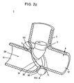
- FIGs. 1 to 5 illustrated embodiments of an angle seat valve 1 have a valve housing 2 with a valve seat 5, an upstream valve inlet 11 and an outflow valve outlet 12, which by a on the end of a spindle 4 arranged in the housing 2 fixed shut-off body 3 against the flowing medium can be shut off.
- the spindle 4 is shown in the Embodiments along their spindle axis SA Move at right angles to the flow direction SR or pipe axis.
- the shut-off body is located 3 on a spherical, spherical or convex pre-curved valve sealing surface 50 of the valve seat 5, that on an imaginary, extending around the valve seat 5 Ring body RK with a torus 6 as the surface lies.
- the location designations of points MP1, MP2, SP1, SP2, TP1, TP2 or sections U1, U2, QF1, QF2 on the torus 6 is on based on the imaginary coordinate system, the origin of which in Center of torus 6 and its axes on the central axis RA and the rotational or central plane RE of the ring body RK lies, with "above” and “below” the position of a valve 1 with top-side spindle extension, as in fig. 1, 2a and 2b, 4 and 5.
- the torus 6 is in the direction of between the valve inlet 11 and valve outlet 12 extending main flow direction SR at an acute angle ⁇ (ring body inclination angle) inclined.
- the ring body angle of inclination ⁇ between the main flow SR on the center plane RE of torus 6 has a value of 0 ° to 90 °, in particular 30 ° to 60 ° and preferably 40 ° up to 50 ° so that the flow cross-section in the closing area the shut-off body 3 a circular or elliptical Has area.
- the shut-off body 3 can have a valve disk 31 with a concave curved plate edge surface as the outer surface 30 (see Fig. 2a) or a truncated cone 3a (see Fig. 2b) or generally a body with a concavely curved outer surface his.
- the contour of the shut-off body 3 is such designed that its outer surface 30 in the closed position at least in a sealing line 33 on one on the inner surface of the jacket 61 of the ring body 6 circumferential surface line 63 rests on which a first (upper) near the spindle Tangential point TP1 as a first surface line point MP1 and a second (lower) tangential point away from the spindle TP2 are arranged as a second surface line point MP2.
- Fig. 1 shows an angle seat valve 1 with a valve seat 5, in which the valve inlet 11 and the valve outlet 12th lie on an axis running in the direction of flow SR and their clear passage in the closing area of the shut-off body 3 corresponds to the nominal size.
- the valve seat 5 has a valve sealing surface 50, which is equal to one part of the toroidal surface.
- the back of the shut-off body 36 is on the valve housing 2 adjusted so that the back 36 in the open state of the Valves 1 bears positively on the housing inner wall.
- the shut-off body 3 is in the area of the receptacle 34 for the Spindle 4 reinforced, i.e. the shape goes from the disc-like Plate shape in a compact block 35 with the Recording 34 above.
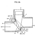
- Fig. 2a is an embodiment of an angle seat valve 1 with a toroidal valve seat 5, whose clear diameter in the closing area of the shut-off body 3 is reduced and its valve inlet 11 and Valve outlet 12 in the flow direction SR coaxially to each other are arranged.
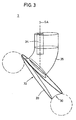
- the shut-off body 3 (see Fig. 3) is the closing side formed by a disk-shaped and wedge-shaped valve plate, where the concave curved plate edge surface Valve disc sealing surface forms (see surface 30 in Fig. 3).
- the valve disc with its all-round sealing surface is in the closed position on the upper section near the spindle of the valve seat 5 almost in a line and on Lower portion of the valve seat 5 in an area.
- the shut-off body 3 has a reinforcement on the spindle side 35 in the form of a curved end piece forming a shaft 35 to accommodate the spindle 4.
- FIG. 2b also shows an embodiment of an angle seat valve 1 with a part of the surface of a Torus corresponding valve seat 5, as shown in Fig. 2a, however, the shut-off body 3 is on the closing side of a truncated cone 3a is formed. Protrudes in the closed position the shut-off body 3.3a in the torus 6 and seals in the Sealing line 33, which corresponds to the surface line 63 of the torus 6 is identical as the line of contact 63, the valve 1 against the flowing medium.
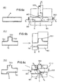
- valve housing 2 the wall thickness s over the entire Cross-section has a constant value is by means of a Manufacturing process for valve body manufactured, whose process steps in FIGS. 6a to 6c figuratively are shown.
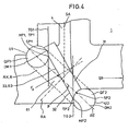
- the valve plate front side 32 is closed the central plane RE of the ring body RK, 6 under one acute angle ⁇ (plate inclination angle) inclined.
- valve disc In the closed position of valve 1, the valve disc is located 31 with a front sealing edge 33 of the valve plate sealing surface 30 on one on an inner surface of the jacket 61 of the torus 6 circumferential surface line 63, whereby on this surface line 63 is a first upper surface line point MP1 and a second lower surface line point MP2 arranged are.
- the first surface line point MP1 is located on a first circumferential section U1 of the first upper cross-sectional area QF1, which runs between a first intersection point SP1 and a first tangential point TP1.
- the first intersection point SP1 is a spindle-side intersection point SP1 of a first diameter DM1 of the upper cross-sectional area QF1 with its circumference U1, which extends in the effective direction of the pressure force F p .
- the first tangential point TP1 is a point of contact a tangent running parallel to the spindle axis SA TG1 to the inner surface 61 of the upper torus section in the first cross-sectional area QF1.
- the second surface line point MP2 lies on a second one Circumferential section U2 of the second, lower cross-sectional area QF2 on which a second intersection SP2 and connects a second tangential point TP2.
- the second intersection point SP2 is an inside of the jacket Intersection SP2 of a second one, in the middle plane RE arranged diameter of the lower cross-sectional area QF2 with its scope U2.
- the second tangent point TP2 is the contact point of one Tangent TG2 running parallel to the spindle axis SA the inner surface 61 of the lower torus section in the second cross-sectional area QF2.
- valve plate 31 undercuts the valve seat 5 in the lower region in the effective direction of the pressure force F p .
- the valve plate 31 lies on the upper side on the seat surface 50.
- valve seat 5 shows the interaction of the forces acting on the valve seat 5 and the spindle 4 with the valve plate 31 (F p , F s ).
- the undercut of the valve seat 5 by the valve plate 31 in the direction of the pressure force F p has the effect that the shut-off body 3 is mounted in the second intersection point SP2 as a support point and on the spindle guide 41 as a further support point C; thus the forces F 2, x , F 2, y and F c are applied to the support points.
- the bearing force F c is a reaction force axially directed to the spindle axis SA to the pressure force F p .
- valve 5 Since the pressure force F p resulting from the differential pressure and the spindle axis SA are arranged at an acute angle to one another, the valve 5 is self-sealing, ie the shut-off body is stably supported in the second intersection point SP2 and the support point C without an acting spindle force F s in the axial direction SA.
- the pressing force F p acting on the shut-off body 3 is balanced in the area of the sealing surface 30, 50 remote from the spindle below the spindle axis SA with the force components F 2, x and F 2, y in the second bearing point SP2 and the bearing force F c acting at right angles on the spindle axis SA ,
- valve plate 31 Since the valve plate 31 is supported in the lower region of the valve seat 5 in the support SP2 and on the spindle guide 41 at right angles to the spindle axis SA, the region of the shut-off body 3 near the spindle above the spindle axis SA is not pushed away from the valve seat 5 by the pressure force F p .
- valve plate 31 allows the plate 31 to be self-centered because the supporting forces F 2, x and F 2, y in the lower region of the valve plate are sufficiently large to overcome the opposing frictional forces in the upper valve plate region and to optimally plate the plate Position to push.
- the self-centering is favored by a larger torus diameter, since then the valve seat sealing surface 50 in the upper torus section QF1 runs steeper to the spindle axis SA.
- FIGS three stage manufacturing process VS1, VS2, VS3 for the Production of an angle seat valve 1 with a (toroidal) Valve seat shown in FIG. 4.
- a blank R is made into a T-piece TS with a through-piece TS1 and a branch TS2 sealed at the end for rough shaping of the outer contour of the valve housing 2 widened.
- the blank R is placed in a one-part or multi-part tool mold W1, which has the outer shape of the T-piece TS, and then after the tool mold W1 is closed by the forming forces F U generated on the end faces of the blank R by pressure stamps DS1, DS2 compressed.
- the tube material is pressed by an internal pressure p i generated outside of the blank R by stretching and pulling operations into an opening W ⁇ provided on the tool side for the formation of the T-web TS1 and thus brought into the desired shape.
- a pressure ram DS3 arranged in the tool opening W ⁇ is a counter-holder DS1 acted upon by the force F G, which supports a uniform design of the branch TS2.
- the blanks R are preferably longitudinally welded tubes used.
- the blank R is preferably filled with an incompressible medium.
- the T-piece (TS) is made in a second process step VS2 transverse to its longitudinal direction of the passage piece TS1 in the area of branch TS2 in a tool die WS2 interspersed.
- the range of throughput D forms the Basic shape for the oblique valve seat 5.
- the closed one The end (cover) of branch TS2 is sheared off.
- the valve seat contour 5 is molded by applying external high pressure by applying external high pressure p a to the inside of the T-piece TS on the internal tool IS1, IS2, IS3.
- a three-part tool IS1, IS2, IS3 is inserted into the branch TS2 and the sections of the passage piece TS2 that are open at the ends.
- the pressure p a applied to the outside of the workpiece TS is generated by compression of an incompressible medium, the force being applied by stamps arranged in the pressure lines of the tool W3.
- FIGS. 7 to 13 further exemplary embodiments the invention explained in more detail.
- the previously mentioned considerations regarding the Relationship of forces and the relative arrangement of each Components of the valve also in those mentioned below Embodiments are to be used.
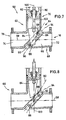
- Figs. 7 to 10 are two exemplary embodiments 60, 60 'shown in longitudinal section, with both valves on and have the same valve housing 62. While the valve 60 is designed as a two-way valve, it is the valve 60 'is a corner valve.
- valve 60 has a T-shaped pipe section 64 on that from a passage 66 forming Through pipe section 68 and a branch pipe section 70 consists.
- the valve housing 62 is made of plastic.
- the opposite axial ends 72, 74 of the through-tube piece 68 form the inlet 76 and the outlet 78 of the valve 60.
- Closes the branch pipe section 70 a bracket 80 for a movement organ in the form a spindle 82 on one end as a bevelled truncated cone 84 wearing.
- a valve seat 86 is formed in the passage channel 66 carries a valve sealing surface 88.
- the valve sealing surface 88 surrounds a surface that is arranged in a plane 90, which is at an acute angle to the passage channel 66 runs.
- the valve sealing surface 88 is part of the surface an imaginary ring body 92, the central plane 94 extends at an acute angle to plane 90.
- the ring body 92 is at an angle from about 45 ° to the longitudinal axis 98 of the passage 66. This longitudinal axis 98 intersects the intersection of the central plane 94 with the central axis 96. Through this intersection the longitudinal axis 100 of the branch pipe section also runs through it 70th
- valve seat 86 is through a bead-shaped deformation of the wall of the passage pipe section 68 trained. Through this bead-like deformation creates an inward protrusion in the Passage channel 66, the surface of which is the inside of a Rings corresponds.
- the ring body 92 itself is oval. The The main axes of this oval are relative to one another in this way dimensioned that in the direction of movement 102 of the shut-off body 84 considers a circular inner surface, in which the truncated cone-shaped shut-off body 84 dips into, to shut off passage 66.
- the shut-off body lies in the shut-off position according to FIG. 7 84 with its outer surface on the valve sealing surface 88 of the valve seat 86. This leads to undercuts between the shut-off body 84 and the valve seat 86th
- valve housing 62 as it in the fig. 7 and 8 is to that this valve housing 62 for both the two-way valve 60 of FIGS. 7 and 8 as well as for the corner valve 60 ' the fig. 9 and 10 can be used.
- Variants are different surface areas of the Valve seat 86 for sealing between the housing 62 and the shut-off body 84 used.
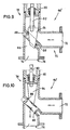
- FIGS. 9 and 10 As far as the individual parts of the Angle valve 60 'those of the through valve 60 of Figs. 7 and 8, they are shown in FIGS. 9 and 10 with the provided with the same reference numerals.
- FIGS. 11 to 13 are different configurations for the formation of the sealing surfaces between the valve seat and the shut-off body shown. Even with these Figures that the parts of the valves 60 and 60 ' the fig. 7 to 10 similar parts in FIGS. 11 to 13 are provided with the same reference numerals.
- valve 60 is sealed by that the valve housing 62 is made of plastic.
- Production-related manufacture of valve housing 62 for example as an injection molded part or by high pressure forming
- a valve sealing surface forms on valve seat 86 88, the quality of which is sufficient to directly deal with the Outside of the shut-off body 84 for sealing the valve 60 interact.
- plastic too other materials such as Metal are used.
- the shut-off body is 84 provided with a material coating 106 that together with the valve sealing surface 88 of the valve seat 86 for sealing of the valve 60 cooperates.
- the material covering 106 can be elastically deformable.
- the housing 62 of the Valve 60 shown in FIG. 12 is made of metal or Plastic.
- valve 60 made of metal.
- valve seat 86 forming the inner protrusion of the through channel 66 a receiving groove 108 inclined at approximately 45 °, into which an oval sealing body 110 made of elastic Plastic material is used.
- This oval ring body 110 seals together with the shut-off body 84.
- annular body 110 forms a sealing surface 88 which only part of the surface of the ring body 110 occupies and, as in the other embodiments of the valve according to FIGS. 7 to 12, essentially contacted the sealing body 84 by line contact and thus sealing the valve 60.
Landscapes
- Engineering & Computer Science (AREA)
- General Engineering & Computer Science (AREA)
- Mechanical Engineering (AREA)
- Lift Valve (AREA)
- Sliding Valves (AREA)
- Taps Or Cocks (AREA)
- Magnetically Actuated Valves (AREA)
- Electrically Driven Valve-Operating Means (AREA)
- Temperature-Responsive Valves (AREA)
Description
- Fig. 1
- eine Schnittansicht eines Schrägsitzventiles mit torusförmigem Ventilsitz und Ventilteller in senkrechter Schnittdarstellung,
- Fig. 2a
- eine perspektivische Ansicht einer weiteren Ausführungsform eines Schrägsitzventiles mit torusförmigem Ventilsitz und Ventilteller in senkrechter Schnittdarstellung,
- Fig. 2b
- eine Seitenansicht einer weiteren Ausführungsform eines Schrägsitzventiles mit torusförmigem Ventilsitz und kegelförmigem Absperrkörper in Schnittdarstellung,
- Fig. 3
- eine Seitenansicht des Absperrkörpers gemäß Fig. 2,
- Fig. 4
- eine schematische Seitenansicht des Hubventiles gemäß Fig. 2 in senkrechter Schnittdarstellung,
- Fig. 5
- eine schematische Seitenansicht des Hubventiles mit einem Lageplan der an dem Absperrkörper wirkenden Kräfte gemäß Fig. 2 in senkrechter Schnittdarstellung,
- Fig. 6a
- einen ersten Verfahrensschritt eines HPF-Verfahrens, in dem ein Rohling zu einem T-Stück aufgeweitet wird,
- Fig. 6b
- einen zweiten Verfahrensschritt des HPF-Verfahrens, in dem das T-Stück durchsetzt und das verschlossene Ende des T-Stückes abgeschert wird,
- Fig. 6c
- einen dritten Verfahrensschritt des HPF-Verfahrens, in dem in das durchsetzte T-Stück die Ventilkontur eingearbeitet wird,
- Fign. 7 und 8
- ein weiteres Ausführungsbeispiel der Erfindung in Form eines Durchlaßventils in geschlossener Stellung (Fig. 7) und in geöffneter Stellung (Fig. 8),
- Fign. 9 und 10
- ein Ausführungsbeispiel der Erfindung in Form eines Eckventils in geschlossener Stellung (Fig. 9) und in geöffneter Stellung (Fig. 10), wobei das Ventilgehäuse gleich dem Ventilgehäuse des Ventils nach den Fign. 7 und 8 ist, und
- Fign. 11 bis 13
- Teillängsschnitte durch weitere Ausführungsbeispiele des erfindungsgemäßen Ventils zur Verdeutlichung unterschiedlicher Möglichkeiten der Ausgestaltung der Ventildichtfläche.
Claims (14)
- Ventil mitdadurch gekennzeichnet,einem Ventilgehäuse (2;62) mit einem Ventileinlass (11;76) und einem Ventilauslass (12;78) und einem Durchlasskanal (66), der sich durch das Ventilgehäuse (2;62) hindurch zwischen dem Ventileinlass (11;76) und dem Ventilauslass (12;78) erstreckt,einem im Durchlasskanal (66) angeordneten Ventilsitz (5;86) mit einer Ventildichtfläche (50;88) undeinem Absperrkörper (3;84), der zum Absperren des Durchlasskanals (66) durch Anlage an der Ventildichtfläche (50;88) zumindest teilweise in den Ventilsitz (5;86) hinein bewegbar ist, und zwar entlang einer Bewegungsrichtung (102), die in einem spitzen Winkel zu derjenigen Ebene (90) verläuft, in der der Ventilsitz (5;86) angeordnet ist,dass die Ventildichtfläche (50;88) des Ventilsitzes (5;86) ballig und Teil der Oberfläche eines imaginären Ringkörpers (6;92) ist,dass der Ringkörper (6;92) eine dem Ventileinlass (11;76) zugewandte Unterseite und eine dem Ventilauslass (12;78) zugewandte Oberseite aufweist und dass die Ventildichtfläche (50;88) von Teilen der Oberfläche des imaginären Ringkörpers (6;92) gebildet ist, die teilweise auf der Oberseite, teilweise auf der Unterseite und teilweise an der Innenseite des imaginären Ringkörpers (6;92) zwischen dessen Ober- und Unterseite angeordnet sind,dass die Ebene (90), in der der Ventilsitz (5;86) angeordnet ist, in einem spitzen Winkel zu derjenigen Ebene (94) verläuft, in der der Ringkörper (6;92) angeordnet ist, unddass der Absperrkörper (3;84) die Ventilsitzebene (90) und die Ringkörperebene (94) bei Anlage an der Ventildichtfläche (50;88) durch-dringt.
- Ventil nach Anspruch 1, dadurch gekennzeichnet, dass der Winkel zwischen 10° und 30° und vorzugsweise etwa 20° beträgt.
- Ventil nach Anspruch 1 oder 2, dadurch gekennzeichnet, dass der imaginäre Ringkörper (6;92) ein kreisrunder, elliptischer oder ovaler Ringkörper mit kreisförmigem, oder anderweitig rundem Querschnitt ist.
- Ventil nach einem der Ansprüche 1 bis 3, dadurch gekennzeichnet, dass die Bewegungsrichtung (102) des Absperrkörpers (3;84) im wesentlichen rechtwinklig zur Erstreckung (98) des Durchlasskanals (66) verläuft.
- Ventil nach einem der Ansprüche 1 bis 4, dadurch gekennzeichnet, dass die Ebene (90), in der der Ventilsitz (5;86) angeordnet ist, unter einem spitzen Ventilsitz-Neigungswinkel zur Erstreckung (98) des Durchlasskanals (66) verläuft.
- Ventil nach einem der Ansprüche 1 bis 5, dadurch gekennzeichnet, dass die Ebene (94), in der der Ringkörper (6;92) angeordnet ist, unter einem spitzen Ringkörper-Neigungswinkel zur Erstreckung (98) des Durchlasskanals (66) verläuft.
- Ventil nach Anspruch 6, dadurch gekennzeichnet, dass der Ringkörper-Neigungswinkel zwischen 30° und 60°, insbesondere zwischen 40° und 50° liegt und vorzugsweise im wesentlichen 45° beträgt.
- Ventil nach einem der Ansprüche 1 bis 7, dadurch gekennzeichnet, dass der Absperrkörper (3;84) als spitzer, stumpfer oder abgeschrägter Kegel ausgebildet ist und der imaginäre Ringkörper (6;92) ein elliptischer Ring mit kreisförmigem Querschnitt ist, wobei der imaginäre Ringkörper (6;92) derart zur Bewegungsrichtung (102) des Absperrkörpers (3;84) geneigt ist, dass er bei Betrachtung in Bewegungsrichtung (102) des Absperrkörpers (3;84) eine kreisrunde Fläche umschließt.
- Ventil nach einem der Ansprüche 1 bis 8, dadurch gekennzeichnet, dass der Ventilsitz (5;86) integraler Bestandteil des Ventilgehäuses (2;62) ist.
- Ventil nach einem der Ansprüche 1 bis 9, dadurch gekennzeichnet, dass das Ventilgehäuse (2;62) ein T-Rohrstück (64) mit einem im wesentlichen geradlinig durchgehenden Durchgangs-Rohrstück (68) und einem dazu im wesentlichen quer verlaufenden Abzweig-Rohrstück (70) ist und dass das Durchgangs-Rohrstück (68) an seiner Innenseite einen umlaufenden vorstehenden sphärischen Flächenabschnitt aufweist, der in einer unter einem Winkel von 45° zur Längsachse (98,100) sowohl des Durchgangs-Rohrstücks (68) als auch des Abzweig-Rohrstücks (70) geneigten Ebene liegt und auf dem die Ventildichtfläche (50;88) liegt, wobei der sphärische Flächenabschnitt entlang eines der beiden Eckenbereiche zwischen dem Durchgangs-Rohrstück (68) und dem Abzweig-Rohrstück (70) verläuft.
- Ventil nach Anspruch 10, dadurch gekennzeichnet, dass der sphärische Flächenabschnitt durch lokale sickenförmige Verformung des T-Rohrstücks (64) gebildet ist.
- Ventil nach einem der Ansprüche 1 bis 11, dadurch gekennzeichnet, dass das Ventilgehäuse (2;62) aus Kunststoff besteht.
- Ventil nach einem der Ansprüche 1 bis 12, dadurch gekennzeichnet, dass das Ventilgehäuse (2;62) ein Spritzgussteil ist.
- Ventil nach einem der Ansprüche 1 bis 13, dadurch gekennzeichnet, dass das Ventilgehäuse (2;62) durch spanlose Umformung eines Rohrstückes gebildet ist.
Applications Claiming Priority (2)
| Application Number | Priority Date | Filing Date | Title |
|---|---|---|---|
| DE19637663A DE19637663C2 (de) | 1996-09-16 | 1996-09-16 | Ventil und Verfahren zu dessen Herstellung |
| DE19637663 | 1996-09-16 |
Publications (3)
| Publication Number | Publication Date |
|---|---|
| EP0829666A2 EP0829666A2 (de) | 1998-03-18 |
| EP0829666A3 EP0829666A3 (de) | 1998-04-01 |
| EP0829666B1 true EP0829666B1 (de) | 2003-03-05 |
Family
ID=7805760
Family Applications (1)
| Application Number | Title | Priority Date | Filing Date |
|---|---|---|---|
| EP97116037A Expired - Lifetime EP0829666B1 (de) | 1996-09-16 | 1997-09-16 | Ventil |
Country Status (8)
| Country | Link |
|---|---|
| US (1) | US6116572A (de) |
| EP (1) | EP0829666B1 (de) |
| JP (1) | JP2001500235A (de) |
| KR (1) | KR20000036167A (de) |
| AT (1) | ATE233873T1 (de) |
| CA (1) | CA2267358A1 (de) |
| DE (2) | DE19637663C2 (de) |
| WO (1) | WO1998011369A1 (de) |
Families Citing this family (13)
| Publication number | Priority date | Publication date | Assignee | Title |
|---|---|---|---|---|
| DE19802993C2 (de) * | 1998-01-28 | 2000-09-07 | Messer Griesheim Gmbh | Armatur |
| DE19816244A1 (de) * | 1998-04-11 | 1999-10-21 | Schulz Gmbh Wilhelm | Gehäuse für Rohrleitungsarmaturen und Verfahren zu ihrer Herstellung |
| JP3943852B2 (ja) * | 2001-03-21 | 2007-07-11 | 株式会社テージーケー | 圧力制御弁 |
| DE20111721U1 (de) * | 2001-07-14 | 2002-11-21 | ARI-Armaturen Albert Richter GmbH & Co KG, 33758 Schloß Holte-Stukenbrock | Hubventil |
| US6698718B2 (en) | 2001-08-29 | 2004-03-02 | Wafermasters, Inc. | Rotary valve |
| GB0200697D0 (en) * | 2002-01-14 | 2002-02-27 | Aeon Valves Ltd | Gate valves |
| JP2007046513A (ja) * | 2005-08-09 | 2007-02-22 | Mitsubishi Motors Corp | 流体制御装置 |
| DE102009021943A1 (de) * | 2009-05-19 | 2010-11-25 | Bürkert Werke GmbH | Verfahren zur Herstellung eines Ventilgehäuses |
| DE102011101948B4 (de) * | 2010-05-19 | 2016-08-11 | Tenneco Gmbh | Verfahren zur Herstellung einer Ventilklappenvorrichtung |
| AU2012321043A1 (en) * | 2011-10-08 | 2013-05-16 | Triteck Limited | Device for a plumbing installation |
| US9200532B2 (en) * | 2012-09-13 | 2015-12-01 | Honeywell International Inc. | Turbine wastegate |
| US8904785B2 (en) | 2012-09-13 | 2014-12-09 | Honeywell International Inc. | Turbine wastegate |
| DE202016000514U1 (de) * | 2016-01-27 | 2017-05-02 | Gebr. Kemper Gmbh + Co. Kg Metallwerke | Absperrarmatur |
Family Cites Families (19)
| Publication number | Priority date | Publication date | Assignee | Title |
|---|---|---|---|---|
| US762436A (en) * | 1902-09-29 | 1904-06-14 | Alfred G Osgood | Valve. |
| US2269404A (en) * | 1940-06-17 | 1942-01-06 | Hugh E Haven | Eddy reducing valve |
| NL6806266A (de) * | 1968-05-03 | 1969-11-05 | ||
| US3519245A (en) * | 1968-08-23 | 1970-07-07 | Westinghouse Electric Corp | Valve structure |
| US3712328A (en) * | 1971-08-05 | 1973-01-23 | Scovill Manufacturing Co | Tire valve core |
| DE2430537A1 (de) * | 1974-04-15 | 1975-10-16 | Mladen Jankovic | Schieberventil |
| US4350176A (en) * | 1980-08-18 | 1982-09-21 | Lace Donald A | Check valve structure |
| GB2085128A (en) * | 1980-10-03 | 1982-04-21 | Saunders Philip Keith | Valves |
| JPS5865374A (ja) * | 1981-10-09 | 1983-04-19 | Eagle Ind Co Ltd | 傾斜弁の閉弁調心機構 |
| DE3609772A1 (de) | 1986-03-22 | 1987-09-24 | Klein Schanzlin & Becker Ag | Hubventil |
| JPH01295085A (ja) * | 1988-05-20 | 1989-11-28 | Kimura Koki Kk | 比例式電動二方弁 |
| DE3901700A1 (de) * | 1989-01-21 | 1990-07-26 | Klein Schanzlin & Becker Ag | Absperr- oder regelarmatur |
| DE3901695A1 (de) * | 1989-01-21 | 1990-07-26 | Klein Schanzlin & Becker Ag | Hubventil |
| DE4001605A1 (de) * | 1990-01-20 | 1991-07-25 | Klein Schanzlin & Becker Ag | Verschlussstueck fuer eine absperrarmatur |
| DE4027459A1 (de) * | 1990-08-30 | 1992-03-12 | Richter Albert Ari Armaturen | Hubventil |
| DE4103083C1 (en) * | 1991-02-01 | 1992-05-27 | H.D. Eichelberg & Co Gmbh, 5750 Menden, De | Steel pipe branch for IC engine exhaust - is formed by integral, hydrostatically shaped component with inner, longitudinal flanges |
| JP2816524B2 (ja) * | 1993-09-22 | 1998-10-27 | 株式会社荏原製作所 | 真空弁 |
| DE4342025A1 (de) * | 1993-12-09 | 1995-06-14 | Richter Albert Ari Armaturen | Armatur |
| DE19504120A1 (de) * | 1995-02-08 | 1996-08-14 | Buerkert Werke Gmbh & Co | Verfahren zur Herstellung eines Ventilgehäuses |
-
1996
- 1996-09-16 DE DE19637663A patent/DE19637663C2/de not_active Expired - Fee Related
-
1997
- 1997-09-16 US US09/254,679 patent/US6116572A/en not_active Expired - Fee Related
- 1997-09-16 AT AT97116037T patent/ATE233873T1/de not_active IP Right Cessation
- 1997-09-16 KR KR1019997002219A patent/KR20000036167A/ko not_active Withdrawn
- 1997-09-16 CA CA002267358A patent/CA2267358A1/en not_active Abandoned
- 1997-09-16 WO PCT/EP1997/005050 patent/WO1998011369A1/de not_active Ceased
- 1997-09-16 JP JP10513281A patent/JP2001500235A/ja active Pending
- 1997-09-16 EP EP97116037A patent/EP0829666B1/de not_active Expired - Lifetime
- 1997-09-16 DE DE59709429T patent/DE59709429D1/de not_active Expired - Lifetime
Also Published As
| Publication number | Publication date |
|---|---|
| ATE233873T1 (de) | 2003-03-15 |
| WO1998011369A1 (de) | 1998-03-19 |
| KR20000036167A (ko) | 2000-06-26 |
| US6116572A (en) | 2000-09-12 |
| CA2267358A1 (en) | 1998-03-19 |
| DE19637663A1 (de) | 1998-04-02 |
| EP0829666A3 (de) | 1998-04-01 |
| JP2001500235A (ja) | 2001-01-09 |
| DE19637663C2 (de) | 1999-03-25 |
| EP0829666A2 (de) | 1998-03-18 |
| DE59709429D1 (de) | 2003-04-10 |
Similar Documents
| Publication | Publication Date | Title |
|---|---|---|
| EP0829666B1 (de) | Ventil | |
| EP2078892B1 (de) | Vakuum-Ventil mit Dichtring | |
| DE2609446A1 (de) | Kugelventil | |
| EP1688654B1 (de) | Vakuumventil | |
| DE2460185C2 (de) | Verfahren zur Herstellung von Dichtungselementen mit hydrodynamischer Wirkung | |
| DE2445106A1 (de) | Drosselklappenventil | |
| DE2943875A1 (de) | Ventil und dichtungssystem hierfuer | |
| EP1848891B1 (de) | Dichtungseinrichtung für einen kraftstoffinjektor sowie verfahren zum abdichten | |
| DE2457230B2 (de) | Hahn zum Absperren und Steuern von Hochtemperatur-Strömungsmedien | |
| DE2424040C3 (de) | Kolben von Schwingungsdämpfern, insbesondere für Kraftfahrzeuge | |
| EP0295479B1 (de) | Dichtverbindung | |
| WO2021018341A1 (de) | Ventil und vorrichtung zur regelung von drücken eines strömungsmittels mit dem ventil sowie vorrichtung zur sicherung des ventils in dem getriebebauteil | |
| EP1936151B1 (de) | Verfahren zum Herstellen einer Vorrichtung zur Steuerung des Durchflusses eines gasförmigen oder flüssigen Mediums | |
| DE4321787C2 (de) | Kugelrückschlagventil | |
| EP4025812B1 (de) | Metallische abdichtung für ein klappenventil | |
| EP4390207B1 (de) | Kupplungsteil für eine hydraulikkupplung | |
| DE2915889C2 (de) | Klappenventil | |
| DE10028503A1 (de) | Dichtungsanordnung für hohe Drücke und Temperaturen | |
| DE10059954B4 (de) | Rückschlagventil | |
| EP2108868B1 (de) | Absperrhahn für den Installationsbereich | |
| EP4293259A1 (de) | Ventil | |
| WO2008132034A1 (de) | Absperrkugel eines kugelhahns und verfahren zu ihrer herstellung | |
| EP1447601B1 (de) | Doppelsitzventil | |
| EP0043590B1 (de) | Flanschverbindung | |
| DE102019209167B4 (de) | Dichtkolben für eine hydraulische Dehnspannhalterung sowie Dehnspannhalterung |
Legal Events
| Date | Code | Title | Description |
|---|---|---|---|
| PUAI | Public reference made under article 153(3) epc to a published international application that has entered the european phase |
Free format text: ORIGINAL CODE: 0009012 |
|
| PUAL | Search report despatched |
Free format text: ORIGINAL CODE: 0009013 |
|
| AK | Designated contracting states |
Kind code of ref document: A2 Designated state(s): AT BE CH DE DK ES FI FR GB GR IE IT LI NL PT SE |
|
| AX | Request for extension of the european patent |
Free format text: AL;LT;LV;RO;SI |
|
| AK | Designated contracting states |
Kind code of ref document: A3 Designated state(s): AT BE CH DE DK ES FI FR GB GR IE IT LI LU MC NL PT SE |
|
| AX | Request for extension of the european patent |
Free format text: AL;LT;LV;RO;SI |
|
| 17P | Request for examination filed |
Effective date: 19980630 |
|
| AKX | Designation fees paid |
Free format text: AT BE CH DE DK ES FI FR GB GR IE IT LI NL PT SE |
|
| RBV | Designated contracting states (corrected) |
Designated state(s): AT BE CH DE DK ES FI FR GB GR IE IT LI NL PT SE |
|
| 17Q | First examination report despatched |
Effective date: 20010503 |
|
| GRAG | Despatch of communication of intention to grant |
Free format text: ORIGINAL CODE: EPIDOS AGRA |
|
| GRAG | Despatch of communication of intention to grant |
Free format text: ORIGINAL CODE: EPIDOS AGRA |
|
| GRAH | Despatch of communication of intention to grant a patent |
Free format text: ORIGINAL CODE: EPIDOS IGRA |
|
| GRAH | Despatch of communication of intention to grant a patent |
Free format text: ORIGINAL CODE: EPIDOS IGRA |
|
| GRAA | (expected) grant |
Free format text: ORIGINAL CODE: 0009210 |
|
| AK | Designated contracting states |
Designated state(s): AT BE CH DE DK ES FI FR GB GR IE IT LI NL PT SE |
|
| PG25 | Lapsed in a contracting state [announced via postgrant information from national office to epo] |
Ref country code: NL Free format text: LAPSE BECAUSE OF FAILURE TO SUBMIT A TRANSLATION OF THE DESCRIPTION OR TO PAY THE FEE WITHIN THE PRESCRIBED TIME-LIMIT Effective date: 20030305 Ref country code: IT Free format text: LAPSE BECAUSE OF FAILURE TO SUBMIT A TRANSLATION OF THE DESCRIPTION OR TO PAY THE FEE WITHIN THE PRESCRIBED TIME-LIMIT;WARNING: LAPSES OF ITALIAN PATENTS WITH EFFECTIVE DATE BEFORE 2007 MAY HAVE OCCURRED AT ANY TIME BEFORE 2007. THE CORRECT EFFECTIVE DATE MAY BE DIFFERENT FROM THE ONE RECORDED. Effective date: 20030305 Ref country code: IE Free format text: LAPSE BECAUSE OF FAILURE TO SUBMIT A TRANSLATION OF THE DESCRIPTION OR TO PAY THE FEE WITHIN THE PRESCRIBED TIME-LIMIT Effective date: 20030305 Ref country code: GR Free format text: LAPSE BECAUSE OF FAILURE TO SUBMIT A TRANSLATION OF THE DESCRIPTION OR TO PAY THE FEE WITHIN THE PRESCRIBED TIME-LIMIT Effective date: 20030305 Ref country code: GB Free format text: LAPSE BECAUSE OF FAILURE TO SUBMIT A TRANSLATION OF THE DESCRIPTION OR TO PAY THE FEE WITHIN THE PRESCRIBED TIME-LIMIT Effective date: 20030305 Ref country code: FR Free format text: LAPSE BECAUSE OF NON-PAYMENT OF DUE FEES Effective date: 20030305 Ref country code: FI Free format text: LAPSE BECAUSE OF FAILURE TO SUBMIT A TRANSLATION OF THE DESCRIPTION OR TO PAY THE FEE WITHIN THE PRESCRIBED TIME-LIMIT Effective date: 20030305 |
|
| REG | Reference to a national code |
Ref country code: GB Ref legal event code: FG4D Free format text: NOT ENGLISH |
|
| REG | Reference to a national code |
Ref country code: CH Ref legal event code: EP |
|
| REG | Reference to a national code |
Ref country code: IE Ref legal event code: FG4D Free format text: GERMAN |
|
| REF | Corresponds to: |
Ref document number: 59709429 Country of ref document: DE Date of ref document: 20030410 Kind code of ref document: P |
|
| PG25 | Lapsed in a contracting state [announced via postgrant information from national office to epo] |
Ref country code: SE Free format text: LAPSE BECAUSE OF FAILURE TO SUBMIT A TRANSLATION OF THE DESCRIPTION OR TO PAY THE FEE WITHIN THE PRESCRIBED TIME-LIMIT Effective date: 20030605 Ref country code: PT Free format text: LAPSE BECAUSE OF FAILURE TO SUBMIT A TRANSLATION OF THE DESCRIPTION OR TO PAY THE FEE WITHIN THE PRESCRIBED TIME-LIMIT Effective date: 20030605 Ref country code: DK Free format text: LAPSE BECAUSE OF FAILURE TO SUBMIT A TRANSLATION OF THE DESCRIPTION OR TO PAY THE FEE WITHIN THE PRESCRIBED TIME-LIMIT Effective date: 20030605 |
|
| NLV1 | Nl: lapsed or annulled due to failure to fulfill the requirements of art. 29p and 29m of the patents act | ||
| GBV | Gb: ep patent (uk) treated as always having been void in accordance with gb section 77(7)/1977 [no translation filed] |
Effective date: 20030305 |
|
| PG25 | Lapsed in a contracting state [announced via postgrant information from national office to epo] |
Ref country code: AT Free format text: LAPSE BECAUSE OF NON-PAYMENT OF DUE FEES Effective date: 20030916 |
|
| PG25 | Lapsed in a contracting state [announced via postgrant information from national office to epo] |
Ref country code: LI Free format text: LAPSE BECAUSE OF NON-PAYMENT OF DUE FEES Effective date: 20030930 Ref country code: ES Free format text: LAPSE BECAUSE OF FAILURE TO SUBMIT A TRANSLATION OF THE DESCRIPTION OR TO PAY THE FEE WITHIN THE PRESCRIBED TIME-LIMIT Effective date: 20030930 Ref country code: CH Free format text: LAPSE BECAUSE OF NON-PAYMENT OF DUE FEES Effective date: 20030930 Ref country code: BE Free format text: LAPSE BECAUSE OF NON-PAYMENT OF DUE FEES Effective date: 20030930 |
|
| REG | Reference to a national code |
Ref country code: IE Ref legal event code: FD4D Ref document number: 0829666E Country of ref document: IE |
|
| PLBE | No opposition filed within time limit |
Free format text: ORIGINAL CODE: 0009261 |
|
| STAA | Information on the status of an ep patent application or granted ep patent |
Free format text: STATUS: NO OPPOSITION FILED WITHIN TIME LIMIT |
|
| EN | Fr: translation not filed | ||
| 26N | No opposition filed |
Effective date: 20031208 |
|
| BERE | Be: lapsed |
Owner name: *SCHLATTMANN JOSEF Effective date: 20030930 |
|
| REG | Reference to a national code |
Ref country code: CH Ref legal event code: PL |
|
| PGFP | Annual fee paid to national office [announced via postgrant information from national office to epo] |
Ref country code: DE Payment date: 20100922 Year of fee payment: 14 |
|
| REG | Reference to a national code |
Ref country code: DE Ref legal event code: R119 Ref document number: 59709429 Country of ref document: DE Effective date: 20120403 |
|
| PG25 | Lapsed in a contracting state [announced via postgrant information from national office to epo] |
Ref country code: DE Free format text: LAPSE BECAUSE OF NON-PAYMENT OF DUE FEES Effective date: 20120403 |