EP0828676B1 - Einrichtung zum ausrichten von bogen - Google Patents
Einrichtung zum ausrichten von bogen Download PDFInfo
- Publication number
- EP0828676B1 EP0828676B1 EP97920555A EP97920555A EP0828676B1 EP 0828676 B1 EP0828676 B1 EP 0828676B1 EP 97920555 A EP97920555 A EP 97920555A EP 97920555 A EP97920555 A EP 97920555A EP 0828676 B1 EP0828676 B1 EP 0828676B1
- Authority
- EP
- European Patent Office
- Prior art keywords
- sheet
- sheets
- alignment
- conveyed
- aligning
- Prior art date
- Legal status (The legal status is an assumption and is not a legal conclusion. Google has not performed a legal analysis and makes no representation as to the accuracy of the status listed.)
- Expired - Lifetime
Links
- 239000000758 substrate Substances 0.000 description 2
- 239000000725 suspension Substances 0.000 description 1
Images

Classifications
-
- B—PERFORMING OPERATIONS; TRANSPORTING
- B65—CONVEYING; PACKING; STORING; HANDLING THIN OR FILAMENTARY MATERIAL
- B65H—HANDLING THIN OR FILAMENTARY MATERIAL, e.g. SHEETS, WEBS, CABLES
- B65H9/00—Registering, e.g. orientating, articles; Devices therefor
- B65H9/10—Pusher and like movable registers; Pusher or gripper devices which move articles into registered position
- B65H9/103—Pusher and like movable registers; Pusher or gripper devices which move articles into registered position acting by friction or suction on the article for pushing or pulling it into registered position, e.g. against a stop
Definitions
- the invention relates to a device for Aligning sheets conveyed on a feed table to in and / or stops arranged transversely to the sheet conveying direction.
- Alignment in the sheet conveying direction takes place by constant or intermittent conveying against front stops.
- Conveyor belts (DE 39 17 072) arranged on the feed table are known for continuous conveying, and clocked rollers (DD 139 706) are known for the cyclical conveying in time with the sheet conveying.
- So-called side draw marks are known for the lateral alignment (DE 29 29 388). If the sheets are conveyed against the stops with too little force, they will not reach the stops and alignment errors will occur. The same effect occurs when the sheets are conveyed to the stops at high speed and then spring back. Alignment errors can also occur if the arches are pressed against the stops with high force and arches are formed.
- US 4 049 256A discloses a device for aligning sheets according to the preamble of claim 1.
- the object of the invention is to create a Device for exact sheet alignment with little effort.
- the sheets 2 to be printed by the system printing unit and any further printing units, if necessary, are fed cyclically to the system printing unit, usually in scaled form.
- the cycle frequency of the sheet conveyance depends on the processing speed of the printing press.
- the sheets 2 conveyed on the feed table 1 of the printing machine are aligned in the sheet travel direction before transfer to the feed printing unit at feed marks 4 arranged transversely to the sheet travel direction 3 (FIG. 1). Then or at the same time, the sheets 2 are aligned transversely to the sheet running direction 3 at a side mark 5 arranged on the side of the feed table 1 (FIG. 2).
- the brands mentioned act as attacks.
- Alignment is carried out by applying a force component to the sheet 2.
- the force component includes a movement component 8 or is composed of a pressure component 7 and a movement component 8 (FIG. 3).
- the force component By means of the force component, the sheet 2 to be aligned is placed on the contact marks 4 and / or the side mark 5 and thus aligned.
- the bow 2 is applied by applying intermittent, ie temporarily interrupting, pulses to the bow.
- Pulse is understood to mean the short-term effect of a physical quantity.
- the impulses are applied using a pulse element 6.
- a pressure component 7 and a movement component 8 or only one movement component with slip are applied to the sheet 2.
- the force-free relaxation of the bow takes place.
- the slip can be selected by changing the size of the pressure component depending on the type of substrate.
- the frequency of the intermittent pulses is much higher than the clock frequency of the conveyed sheets.
- the clock frequency of the conveyed sheets is in the order of several Hertz (up to approx.
- the movement components are applied to the sheet separately in phase or out of phase for each alignment direction (directional arrows in FIG. 2). With phase-shifted alignment, uninfluenced alignment in the side and sheet conveying direction is possible, ie lateral alignment is unaffected by the alignment on the contact marks and vice versa. By applying the movement components at an angle to the sheet conveying direction (dashed arrow in FIG. 2), it is possible to align the sheet in both alignment directions with a single pulse element 6.
- the angle is adjustable so that it is possible to choose the optimum angle depending on the type of substrate and to choose the direction of movement of the sheet to be aligned (right or left side stop 5).
- the intermittent impulses are applied either rotatively or translatively.
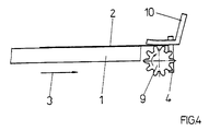
- the rotary application is possible, for example, with a rotating element 9 rotating at a high frequency with several tooth-like elevations which touch the arch in the active phase (FIG. 4).
- the rotary element 9 is arranged either parallel or perpendicular to the sheet conveying plane. In the embodiment shown in Fig. 4, the rotary element 9 is arranged in a vertical position below the sheet 2; A support element 10 is arranged above the arch. The rotary element 9 presses the sheet against the support element 10.
- the feed table 1 acted as a support element.
Landscapes
- Engineering & Computer Science (AREA)
- Mechanical Engineering (AREA)
- Registering Or Overturning Sheets (AREA)
Description
Für die seitliche Ausrichtung sind (DE 29 29 388) sog. Seitenziehmarken bekannt. Werden die Bogen mit zu geringer Kraft gegen die Anschläge gefördert, erreichen sie die Anschläge nicht und es entstehen Ausrichtfehler. Der gleiche Effekt tritt auf, wenn die Bogen mit hoher Geschwindigkeit an die Anschläge gefördert werden und anschließend zurückspringen. Ausrichtfehler können auch entstehen, wenn die Bogen mit hoher Kraft an die Anschläge gedrückt werden und Bogenbauschen entstehen.
- Fig. 1
- Anlegtisch Seitenansicht
- Fig. 2
- Anlegtisch Draufsicht
- Fig. 3
- Kraftkomponenten
- Fig. 4
- Rotativ arbeitendes Impulselement
Die auf dem Anlegtisch 1 der Druckmaschine geförderten Bogen 2 werden vor Übergabe an das Anlagedruckwerk an quer zur Bogenlaufrichtung 3 angeordneten Anlegmarken 4 in Bogenlaufrichtung ausgerichtet (Fig. 1). Danach oder zeitgleich werden die Bogen 2 an einer seitlich am Anlegtisch 1 angeordneten Seitenmarke 5 quer zur Bogenlaufrichtung 3 ausgerichtet (Fig. 2). Die genannten Marken fungieren dabei als Anschläge.
Das Ausrichten erfolgt durch das Aufbringen einer Kraftkomponente auf den Bogen 2. Die Kraftkomponente beinhaltet eine Bewegungskomponente 8 oder setzt sich aus einer Andrückkomponente 7 und einer Bewegungskomponente 8 zusammen (Fig. 3).
Vermittels der Kraftkomponente wird der auszurichtende Bogen 2 an die Anlegmarken 4 und/oder die Seitenmarke 5 angelegt und damit ausgerichtet.
Dabei wird in der Wirkphase der Impulse eine Andrückkomponente 7 und eine Bewegungskomponente 8 oder nur eine Bewegungskomponente unter Schlupf auf den Bogen 2 aufgebracht. In der Nichtwirkphase der Impulse (Aussetzphase) erfolgt die kraftfreie Entspannung des Bogens. Der Schlupf kann durch die Veränderung der Größe der Andrückkomponente je nach Bedruckstoffart gewählt werden.
Die Frequenz der intermittierenden Impulse ist wesentlich größer als die Taktfrequenz der geförderten Bogen. Die Taktfrequenz der geförderten Bogen liegt in der Größenordnung von mehreren Hertz (bis ca. 5 Hz) und die Frequenz der intermittierenden Impulse in der Größenordnung über 50 Hz, vorzugsweise in der Größenordnung von 200 - 400 Hz.
Die Impulsfrequenz ist einstellbar bzw. in Relation zur Maschinengeschwindigkeit steuerbar.
Die Bewegungskomponenten werden für jede Ausrichtrichtung getrennt phasengleich oder phasenversetzt auf den Bogen aufgebracht (Richtungspfeile in Fig. 2). Bei der phasenversetzten Ausrichtung ist ein unbeeinflußtes Ausrichten in Seiten- und Bogenförderrichtung möglich, d.h. die seitliche Ausrichtung erfolgt unbeeinflußt von der Ausrichtung an den Anlegmarken und umgekehrt. Durch ein Aufbringen der Bewegungskomponenten unter einem Winkel zur Bogenförderrichtung (gestrichelte Pfeildarstellung in Fig. 2) ist es möglich, den Bogen in beiden Ausrichtrichtungen mit einem einzigen Impulselement 6 auszurichten. Der Winkel ist einstellbar, damit ist es möglich je nach Bedruckstoffart optimale Winkel auszuwählen und die Bewegungsrichtung des auszurichtenden Bogens (rechts oder links angeordneter Seitenanschlag 5) zu wählen.
Die intermittierenden Impulse werden entweder rotativ oder translativ aufgebracht. Das rotative Aufbringen ist beispielsweise mit einem mit hoher Frequenz umlaufenden rotativen Element 9 mit mehreren zahnartigen Erhöhungen, die den Bogen in der Wirkphase berühren, möglich (Fig. 4). Das rotative Element 9 ist entweder parallel oder senkrecht zur Bogenförderebene angeordnet.
Bei der in Fig. 4 dargestellten Ausführungsform ist das rotative Element 9 in senkrechter Stellung unterhalb des Bogens 2 angeordnet; oberhalb des Bogens ist ein Abstützelement 10 angeordnet. Das rotative Element 9 drückt dabei den Bogen gegen das Abstützelement 10. Bei Anordnung des rotativen Elementes oberhalb des Bogens fungierte der Anlegtisch 1 als Abstützelement.
- 1
- Anlegtisch
- 2
- Bogen
- 3
- Bogenförderrichtung
- 4
- Anlegmarke
- 5
- Se it enmarke
- 6
- Impulselement
- 7
- Andrückkomponente
- 8
- Bewegungskomponente
- 9
- rotatives Element
- 10
- Abstützelement
- 11
- Schwinganker
Claims (2)
- Einrichtung zum Ausrichten von auf einem Anlegtisch geförderten Bogen an mindestens einem in und/oder quer zur Bogenförderung angeordneten Anschlag, dadurch gekennzeichnet, dass im Ausrichtbereich einer Seite des Bogens (2) ein Abstützelement (10) und der anderen Seite des Bogens ein intermittierende stoßartige Impulse auf den Bogen aufbringendes rotatives zahnradähnliches Impulselement (6) mit mehreren zahnartigen Erhöhungen zugeordnet ist.
- Einrichtung zum Ausrichten nach Anspruch 1, dadurch gekennzeichnet, dass die Impulsfrequenz des Impulselementes (6) mit größer 50 Hz wesentlich größer als die Taktfrequenz der geförderten Bogen ist.
Applications Claiming Priority (3)
| Application Number | Priority Date | Filing Date | Title |
|---|---|---|---|
| DE19612545A DE19612545A1 (de) | 1996-03-29 | 1996-03-29 | Verfahren und Einrichtung zum Ausrichten von Bogen |
| DE19612545 | 1996-03-29 | ||
| PCT/DE1997/000639 WO1997036814A1 (de) | 1996-03-29 | 1997-03-25 | Verfahren und einrichtung zum ausrichten von bogen |
Publications (2)
| Publication Number | Publication Date |
|---|---|
| EP0828676A1 EP0828676A1 (de) | 1998-03-18 |
| EP0828676B1 true EP0828676B1 (de) | 2002-01-16 |
Family
ID=7789852
Family Applications (1)
| Application Number | Title | Priority Date | Filing Date |
|---|---|---|---|
| EP97920555A Expired - Lifetime EP0828676B1 (de) | 1996-03-29 | 1997-03-25 | Einrichtung zum ausrichten von bogen |
Country Status (3)
| Country | Link |
|---|---|
| EP (1) | EP0828676B1 (de) |
| DE (2) | DE19612545A1 (de) |
| WO (1) | WO1997036814A1 (de) |
Families Citing this family (1)
| Publication number | Priority date | Publication date | Assignee | Title |
|---|---|---|---|---|
| DE10129744A1 (de) * | 2001-06-20 | 2003-01-09 | Koenig & Bauer Ag | Verfahren und Vorrichtungen zur Ausrichtung eines Bogens |
Family Cites Families (4)
| Publication number | Priority date | Publication date | Assignee | Title |
|---|---|---|---|---|
| US3747921A (en) * | 1971-12-28 | 1973-07-24 | Ibm | Document feed device |
| US3908986A (en) * | 1973-06-15 | 1975-09-30 | Ibm | Sheet aligning mechanism |
| US4049256A (en) * | 1976-06-07 | 1977-09-20 | International Business Machines Corporation | Document alignment assembly |
| JP2725873B2 (ja) * | 1990-03-05 | 1998-03-11 | キヤノン株式会社 | シート送り装置 |
-
1996
- 1996-03-29 DE DE19612545A patent/DE19612545A1/de not_active Withdrawn
-
1997
- 1997-03-25 EP EP97920555A patent/EP0828676B1/de not_active Expired - Lifetime
- 1997-03-25 WO PCT/DE1997/000639 patent/WO1997036814A1/de not_active Ceased
- 1997-03-25 DE DE59705993T patent/DE59705993D1/de not_active Expired - Fee Related
Also Published As
| Publication number | Publication date |
|---|---|
| DE59705993D1 (de) | 2002-02-21 |
| EP0828676A1 (de) | 1998-03-18 |
| WO1997036814A1 (de) | 1997-10-09 |
| DE19612545A1 (de) | 1997-10-02 |
Similar Documents
| Publication | Publication Date | Title |
|---|---|---|
| EP1500504B1 (de) | Vorrichtung zum Bedrucken von flachen Werkstücken aus Holzwerkstoff | |
| EP0425913B1 (de) | Bogenverarbeitende Druckmaschine für Mehrfarbendruck | |
| EP0819521A3 (de) | Rotationsdruckmaschine mit einer Einrichtung zum Behandeln der Oberfläche von Bogen | |
| DE2452050C2 (de) | Vorrichtung zum passergerechten Anlegen von Bogen in Bogenrotationsdruckmaschinen | |
| DE1611190B2 (de) | Rotationsvervielfaeltigungsmaschine | |
| DE4114479C1 (de) | ||
| DE69308635T2 (de) | Einband-Ausgleichvorrichtung für Buchbindevorrichtung | |
| DE19612544B4 (de) | Einrichtung zum Ausrichten von Bogen | |
| DE19612542B4 (de) | Einrichtung zum Ausrichten von Bogen | |
| EP0212365B1 (de) | Bogengreifereinrichtung für Bogenrotationdruckmaschinen | |
| DE19615288B4 (de) | Einrichtung zum Ausrichten von Bogen | |
| WO1997036814A1 (de) | Verfahren und einrichtung zum ausrichten von bogen | |
| DE69018710T2 (de) | Bogentransportvorrichtung. | |
| CH645573A5 (de) | Sauger in bogenwendeeinrichtungen von schoen- und widerdruckmaschinen. | |
| DE102005002507A1 (de) | Vorrichtung zur maschinellen Handhabung von Bogen aus Bedruckstoff | |
| DE19612554B4 (de) | Einrichtung zum Ausrichten von Bogen | |
| DE2237567A1 (de) | Mehrfarben-rotationsblechtafeldruckmaschine | |
| DE19615289A1 (de) | Einrichtung zum Ausrichten von Bogen | |
| EP1882659A2 (de) | Bogenstanz- und -prägemaschine und Verfahren zur Bogenausrichtung | |
| EP0358076B1 (de) | Mechanische Bogenleiteinrichtung in der Bogenanlage an Druckmaschinen | |
| EP1356932B1 (de) | Antrieb eines Vorgreifers | |
| EP0981446A1 (de) | Schräglagekompensation für bogen in einer druckmaschine mit bebilderungseinrichtung | |
| DE102022104070B4 (de) | Vorrichtung und Verfahren zum Behandeln von Substraten | |
| EP1454744B1 (de) | Bogenanlage | |
| DE3710756A1 (de) | Bogengreifereinrichtung |
Legal Events
| Date | Code | Title | Description |
|---|---|---|---|
| PUAI | Public reference made under article 153(3) epc to a published international application that has entered the european phase |
Free format text: ORIGINAL CODE: 0009012 |
|
| AK | Designated contracting states |
Kind code of ref document: A1 Designated state(s): DE FR GB IT NL |
|
| 17P | Request for examination filed |
Effective date: 19980718 |
|
| RAP1 | Party data changed (applicant data changed or rights of an application transferred) |
Owner name: KOENIG & BAUER AKTIENGESELLSCHAFT |
|
| 17Q | First examination report despatched |
Effective date: 20000703 |
|
| RTI1 | Title (correction) |
Free format text: DEVICE FOR ALIGNING SHEETS |
|
| GRAG | Despatch of communication of intention to grant |
Free format text: ORIGINAL CODE: EPIDOS AGRA |
|
| RTI1 | Title (correction) |
Free format text: DEVICE FOR ALIGNING SHEETS |
|
| GRAG | Despatch of communication of intention to grant |
Free format text: ORIGINAL CODE: EPIDOS AGRA |
|
| GRAH | Despatch of communication of intention to grant a patent |
Free format text: ORIGINAL CODE: EPIDOS IGRA |
|
| GRAG | Despatch of communication of intention to grant |
Free format text: ORIGINAL CODE: EPIDOS AGRA |
|
| GRAH | Despatch of communication of intention to grant a patent |
Free format text: ORIGINAL CODE: EPIDOS IGRA |
|
| GRAA | (expected) grant |
Free format text: ORIGINAL CODE: 0009210 |
|
| REG | Reference to a national code |
Ref country code: GB Ref legal event code: IF02 |
|
| AK | Designated contracting states |
Kind code of ref document: B1 Designated state(s): DE FR GB IT NL |
|
| PG25 | Lapsed in a contracting state [announced via postgrant information from national office to epo] |
Ref country code: NL Free format text: LAPSE BECAUSE OF FAILURE TO SUBMIT A TRANSLATION OF THE DESCRIPTION OR TO PAY THE FEE WITHIN THE PRESCRIBED TIME-LIMIT Effective date: 20020116 Ref country code: IT Free format text: LAPSE BECAUSE OF FAILURE TO SUBMIT A TRANSLATION OF THE DESCRIPTION OR TO PAY THE FEE WITHIN THE PRESCRIBED TIME-LIMIT;WARNING: LAPSES OF ITALIAN PATENTS WITH EFFECTIVE DATE BEFORE 2007 MAY HAVE OCCURRED AT ANY TIME BEFORE 2007. THE CORRECT EFFECTIVE DATE MAY BE DIFFERENT FROM THE ONE RECORDED. Effective date: 20020116 |
|
| REF | Corresponds to: |
Ref document number: 59705993 Country of ref document: DE Date of ref document: 20020221 |
|
| GBT | Gb: translation of ep patent filed (gb section 77(6)(a)/1977) |
Effective date: 20020417 |
|
| NLV1 | Nl: lapsed or annulled due to failure to fulfill the requirements of art. 29p and 29m of the patents act | ||
| ET | Fr: translation filed | ||
| PLBE | No opposition filed within time limit |
Free format text: ORIGINAL CODE: 0009261 |
|
| STAA | Information on the status of an ep patent application or granted ep patent |
Free format text: STATUS: NO OPPOSITION FILED WITHIN TIME LIMIT |
|
| 26N | No opposition filed | ||
| PGFP | Annual fee paid to national office [announced via postgrant information from national office to epo] |
Ref country code: GB Payment date: 20080320 Year of fee payment: 12 |
|
| PGFP | Annual fee paid to national office [announced via postgrant information from national office to epo] |
Ref country code: FR Payment date: 20080314 Year of fee payment: 12 Ref country code: DE Payment date: 20080325 Year of fee payment: 12 |
|
| GBPC | Gb: european patent ceased through non-payment of renewal fee |
Effective date: 20090325 |
|
| REG | Reference to a national code |
Ref country code: FR Ref legal event code: ST Effective date: 20091130 |
|
| PG25 | Lapsed in a contracting state [announced via postgrant information from national office to epo] |
Ref country code: DE Free format text: LAPSE BECAUSE OF NON-PAYMENT OF DUE FEES Effective date: 20091001 |
|
| PG25 | Lapsed in a contracting state [announced via postgrant information from national office to epo] |
Ref country code: GB Free format text: LAPSE BECAUSE OF NON-PAYMENT OF DUE FEES Effective date: 20090325 Ref country code: FR Free format text: LAPSE BECAUSE OF NON-PAYMENT OF DUE FEES Effective date: 20091123 |