EP0828064A2 - Kreisplattenfeder - Google Patents
Kreisplattenfeder Download PDFInfo
- Publication number
- EP0828064A2 EP0828064A2 EP97108513A EP97108513A EP0828064A2 EP 0828064 A2 EP0828064 A2 EP 0828064A2 EP 97108513 A EP97108513 A EP 97108513A EP 97108513 A EP97108513 A EP 97108513A EP 0828064 A2 EP0828064 A2 EP 0828064A2
- Authority
- EP
- European Patent Office
- Prior art keywords
- plate spring
- circular plate
- base portion
- resilient support
- annular base
- Prior art date
- Legal status (The legal status is an assumption and is not a legal conclusion. Google has not performed a legal analysis and makes no representation as to the accuracy of the status listed.)
- Granted
Links
Images


Classifications
-
- F—MECHANICAL ENGINEERING; LIGHTING; HEATING; WEAPONS; BLASTING
- F01—MACHINES OR ENGINES IN GENERAL; ENGINE PLANTS IN GENERAL; STEAM ENGINES
- F01N—GAS-FLOW SILENCERS OR EXHAUST APPARATUS FOR MACHINES OR ENGINES IN GENERAL; GAS-FLOW SILENCERS OR EXHAUST APPARATUS FOR INTERNAL-COMBUSTION ENGINES
- F01N13/00—Exhaust or silencing apparatus characterised by constructional features
- F01N13/18—Construction facilitating manufacture, assembly, or disassembly
- F01N13/1805—Fixing exhaust manifolds, exhaust pipes or pipe sections to each other, to engine or to vehicle body
- F01N13/1811—Fixing exhaust manifolds, exhaust pipes or pipe sections to each other, to engine or to vehicle body with means permitting relative movement, e.g. compensation of thermal expansion or vibration
- F01N13/1816—Fixing exhaust manifolds, exhaust pipes or pipe sections to each other, to engine or to vehicle body with means permitting relative movement, e.g. compensation of thermal expansion or vibration the pipe sections being joined together by flexible tubular elements only, e.g. using bellows or strip-wound pipes
-
- F—MECHANICAL ENGINEERING; LIGHTING; HEATING; WEAPONS; BLASTING
- F01—MACHINES OR ENGINES IN GENERAL; ENGINE PLANTS IN GENERAL; STEAM ENGINES
- F01N—GAS-FLOW SILENCERS OR EXHAUST APPARATUS FOR MACHINES OR ENGINES IN GENERAL; GAS-FLOW SILENCERS OR EXHAUST APPARATUS FOR INTERNAL-COMBUSTION ENGINES
- F01N1/00—Silencing apparatus characterised by method of silencing
- F01N1/003—Silencing apparatus characterised by method of silencing by using dead chambers communicating with exhaust gas flow passages
- F01N1/006—Silencing apparatus characterised by method of silencing by using dead chambers communicating with exhaust gas flow passages comprising at least one perforated tube extending from inlet to outlet of the silencer
-
- F—MECHANICAL ENGINEERING; LIGHTING; HEATING; WEAPONS; BLASTING
- F01—MACHINES OR ENGINES IN GENERAL; ENGINE PLANTS IN GENERAL; STEAM ENGINES
- F01N—GAS-FLOW SILENCERS OR EXHAUST APPARATUS FOR MACHINES OR ENGINES IN GENERAL; GAS-FLOW SILENCERS OR EXHAUST APPARATUS FOR INTERNAL-COMBUSTION ENGINES
- F01N1/00—Silencing apparatus characterised by method of silencing
- F01N1/02—Silencing apparatus characterised by method of silencing by using resonance
- F01N1/023—Helmholtz resonators
-
- F—MECHANICAL ENGINEERING; LIGHTING; HEATING; WEAPONS; BLASTING
- F01—MACHINES OR ENGINES IN GENERAL; ENGINE PLANTS IN GENERAL; STEAM ENGINES
- F01N—GAS-FLOW SILENCERS OR EXHAUST APPARATUS FOR MACHINES OR ENGINES IN GENERAL; GAS-FLOW SILENCERS OR EXHAUST APPARATUS FOR INTERNAL-COMBUSTION ENGINES
- F01N13/00—Exhaust or silencing apparatus characterised by constructional features
- F01N13/18—Construction facilitating manufacture, assembly, or disassembly
- F01N13/1805—Fixing exhaust manifolds, exhaust pipes or pipe sections to each other, to engine or to vehicle body
- F01N13/1811—Fixing exhaust manifolds, exhaust pipes or pipe sections to each other, to engine or to vehicle body with means permitting relative movement, e.g. compensation of thermal expansion or vibration
-
- F—MECHANICAL ENGINEERING; LIGHTING; HEATING; WEAPONS; BLASTING
- F16—ENGINEERING ELEMENTS AND UNITS; GENERAL MEASURES FOR PRODUCING AND MAINTAINING EFFECTIVE FUNCTIONING OF MACHINES OR INSTALLATIONS; THERMAL INSULATION IN GENERAL
- F16L—PIPES; JOINTS OR FITTINGS FOR PIPES; SUPPORTS FOR PIPES, CABLES OR PROTECTIVE TUBING; MEANS FOR THERMAL INSULATION IN GENERAL
- F16L27/00—Adjustable joints; Joints allowing movement
- F16L27/10—Adjustable joints; Joints allowing movement comprising a flexible connection only
- F16L27/107—Adjustable joints; Joints allowing movement comprising a flexible connection only the ends of the pipe being interconnected by a flexible sleeve
- F16L27/11—Adjustable joints; Joints allowing movement comprising a flexible connection only the ends of the pipe being interconnected by a flexible sleeve the sleeve having the form of a bellows with multiple corrugations
-
- F—MECHANICAL ENGINEERING; LIGHTING; HEATING; WEAPONS; BLASTING
- F16—ENGINEERING ELEMENTS AND UNITS; GENERAL MEASURES FOR PRODUCING AND MAINTAINING EFFECTIVE FUNCTIONING OF MACHINES OR INSTALLATIONS; THERMAL INSULATION IN GENERAL
- F16L—PIPES; JOINTS OR FITTINGS FOR PIPES; SUPPORTS FOR PIPES, CABLES OR PROTECTIVE TUBING; MEANS FOR THERMAL INSULATION IN GENERAL
- F16L51/00—Expansion-compensation arrangements for pipe-lines
- F16L51/02—Expansion-compensation arrangements for pipe-lines making use of a bellows or an expansible folded or corrugated tube
- F16L51/025—Expansion-compensation arrangements for pipe-lines making use of a bellows or an expansible folded or corrugated tube with several corrugations
- F16L51/027—Expansion-compensation arrangements for pipe-lines making use of a bellows or an expansible folded or corrugated tube with several corrugations with external reinforcement
-
- F—MECHANICAL ENGINEERING; LIGHTING; HEATING; WEAPONS; BLASTING
- F01—MACHINES OR ENGINES IN GENERAL; ENGINE PLANTS IN GENERAL; STEAM ENGINES
- F01N—GAS-FLOW SILENCERS OR EXHAUST APPARATUS FOR MACHINES OR ENGINES IN GENERAL; GAS-FLOW SILENCERS OR EXHAUST APPARATUS FOR INTERNAL-COMBUSTION ENGINES
- F01N2490/00—Structure, disposition or shape of gas-chambers
- F01N2490/15—Plurality of resonance or dead chambers
- F01N2490/155—Plurality of resonance or dead chambers being disposed one after the other in flow direction
-
- F—MECHANICAL ENGINEERING; LIGHTING; HEATING; WEAPONS; BLASTING
- F01—MACHINES OR ENGINES IN GENERAL; ENGINE PLANTS IN GENERAL; STEAM ENGINES
- F01N—GAS-FLOW SILENCERS OR EXHAUST APPARATUS FOR MACHINES OR ENGINES IN GENERAL; GAS-FLOW SILENCERS OR EXHAUST APPARATUS FOR INTERNAL-COMBUSTION ENGINES
- F01N2490/00—Structure, disposition or shape of gas-chambers
- F01N2490/20—Chambers being formed inside the exhaust pipe without enlargement of the cross section of the pipe, e.g. resonance chambers
Definitions
- the present invention relates in general to springs, and more particularly to plate springs used in an exhaust pipe line of an internal combustion engine. More specifically, the present invention is concerned with circular plate springs for use in a so-called flexible pipe unit which is installed in the exhaust pipe line to absorb or compensate inevitable dimensional change of the pipe line during practical usage of the same.
- the flexible pipe unit is a device installed in an exhaust pipe line for absorbing or compensating an inevitable dimensional change of the pipe line during practical use of the same.
- the flexible pipe unit has a spring or springs installed therein.
- Some of the springs are of a circular plate type.
- some of the springs of this circular plate type have failed to exhibit a satisfied spring function when installed in the flexible pipe unit.
- a circular plate spring for use in a flexible pipe unit.
- the circular plate spring comprises an annular base portion constructed of a spring metal plate, and a plurality of equally spaced resilient support portions integral with the annular base portion, the resilient support portions being raised from the annular base portion so that each support portion is inclined relative to an imaginary plane on which the annular base portion lies.
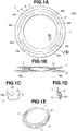
- FIG. 1A there is shown a circular plate spring 10A which is a first embodiment of the present invention.
- the circular plate spring 10A is made of a spring metal plate, such as spring steel, spring stainless steel or the like. When the metal plate is a stainless steel, the thickness of the same is about 0.8 to 2.0 mm. As is seen from Fig. 1A, the circular plate spring 10A is produced by providing a circular spring metal plate with a concentric opening 11 and four round cuts 12a, 12b, 12c and 12d. Stamping or press machines may be used for production of the spring 10A. These four cuts 12a, 12b, 12c and 12d are arranged in equally spaced intervals. As shown, each cut includes an outer round part and an inner round part which are mated at a junction portion. That is, the outer round part of each cut is positioned outside of the inner round part of the neighboring cut. With these four cuts 12a, 12b, 12c and 12d, the plate spring 10A is shaped to have a diametrically larger annular end part "X", a diametrically smaller annular end part "Y" and an intermediate annular part "Z”.
- the circular plate spring 10A has four equally spaced rectangular stopper pieces 14a, 14b, 14c and 14d possessed by and bent back onto the diametrically larger annular end part "X". As shown, each stopper piece 14a, 14b, 14c or 14d extends to the intermediate annular part "Z".
- the diametrically larger and smaller annular end parts "X" and "Y" are axially pulled in opposite directions to such a degree as to have a certain thickness as shown in Fig. 1B. That is, in practical use, the intermediate annular part "Z” transforms into four inclined resilient supports extending between the larger and smaller annular end parts "X" and "Y".
- Fig. 1C shows a method of bending back each stopper piece 14a (14b, 14c or 14d) onto the larger annular end part "X".
- Designated by numeral 16 is a round recess 16 formed near the root of the stopper piece 14a.
- the root of the stopper piece 14a is heated to a certain level by a heater (not shown) put in the round recess 16, and then the stopper piece 14a is bent along a bending line "L".
- a flexible pipe unit 50 to which two circular plate springs 10A-1 and 10A-2 of the first embodiment are practically applied.
- the unit 50 comprises a metal bellows 52 having front and rear open ends respectively connected to front and rear exhaust pipes 102 and 104. Coaxially disposed about the bellows 52 is a cylindrical outer case 54 which has front and rear open ends 54a and 54b radially inwardly bent. A front inner pipe 56a extends coaxially in the bellows 52 from the front open end of the bellows 52 toward the rear open end of the same, and a rear inner pipe 56b extends coaxially in the bellows 52 from the rear open end of the bellows 52 toward the front open end of the same. Front and rear spring holders 58a and 58b are secured or welded to the front and rear open ends of the bellows 52 respectively. Each spring holder 58a or 58b is formed with an annular flange part (no numeral) projected radially outward.
- one circular plate springs 10A-1 is compressed between the front bent end 54a of the outer case 54 and the raised annular flange part of the front spring holder 58a
- the other circular plate spring 10A-2 is compressed between the rear bent end 54b of the outer case 54 and the raised annular flange part of the rear spring holder 58b.
- the stopper pieces 14a, 14b, 14c and 14d of each plate spring 10A-1 or 10A-2 are welded to the front bent end 54a of the outer case 54, and the diametrically smaller end part "Y" of each plate spring 10A-1 or 10A-2 is welded to the raised annular flange part of the front or rear spring holder 58a or 58b.
- the annular plate springs 10A-1 and 10A-2 are axially expanded or compressed.
- the outer case 54 can be stably held around the bellows 52 without being affected by the dimensional change of the bellows 52. That is, in this case, the plate springs 10A-1 and 10A-2 absorb the axial deformation of the bellows 52. Due to the nature of the plate spring 10A having the above-mentioned construction, the springs 10A-1 and 10A-2 can also absorb a transverse deformation of the bellows 52 effectively.
- each plate spring 10A-1 or 10A-2 is compressed to such a degree that the inclined resilient supports "Z" thereof are brought into contact with the stopper pieces 14a, 14b, 14c and 14d, as is seen from Fig. 3. With this, excessive expansion of the bellows 52 is suppressed.
- FIG. 4A and 4B there is shown a circular plate spring 10B which is a second embodiment of the present invention.
- the circular plate spring 10B is made of a spring metal plate, like in the case of the above-mentioned first embodiment 10A.
- the plate spring 10B is produced by providing a circular spring metal plate with a smaller center opening 18 and six round cuts 20a, 20a', 20b, 20b', 20c and 20c'. As shown, the round cuts 20a and 20a' are arranged on diametrically opposed portions of a first imaginary circle concentric with the center opening 18, the round cuts 20b and 20b' are arranged on diametrically opposed portions of a second imaginary circle concentric with the center opening 18 and the round cuts 20c and 20c' are arranged on diametrically opposed portions of a third imaginary circle concentric with the center opening 18.
- the plate spring 10B is shaped to have a diametrically larger annular end part "X", a diametrically smaller annular end part "Y", an outer intermediate annular part "Z1" and an inner intermediate annular part "Z2".
- the larger and smaller annular end parts "X" and “Y” are axially pulled in opposite directions to such a degree as to have a certain thickness as shown in Fig. 4B. That is, in practical use, the outer and inner intermediate annular parts “Z1” and “Z2” transform into a pair of stepped resilient supports extending between the larger and smaller annular end parts "X” and “Y", each support including an inclined resilient support part “Z1” and another inclined resilient support part “Z2”, as is understood from Fig. 4B.
- the plate spring 10B of this second embodiment can be practically applied to the flexible pipe unit 50 in place of the springs 10A-1 and 10A-2.
- FIG. 5A and 5B there is shown a circular plate spring 10C which is a third embodiment of the present invention.
- the circular plate spring 10C is made of a spring metal plate, like in the case of the above-mentioned first embodiment 10A.
- the plate spring 10C is produced by providing a circular spring metal plate with an opening 24 having three tail-shaped portions. With the opening 24, the metal plate is shaped to comprise a diametrically larger annular base part 26 and equally spaced three blade parts 28a, 28b and 28c each extending radially inward from the annular base part 26. As is understood from Fig. 5B, to provide the spring 10C with a spring function, the three blade parts 28a, 28b and 28c are somewhat raised from the annular base part 26 so that they have mutually converging upper ends.
- the annular base part 26 servers as the diametrically larger annular end part of the spring 10A of the first embodiment, and the mutually converging upper ends of the blades 28a, 28b and 28c serve as the diametrically smaller annular end part of the spring 10A.
- FIG. 6A and 6B there is shown a circular plate spring 10D which is a fourth embodiment of the present invention.
- the circular plate spring 10C is made of a spring metal plate, like in the case of the above-mentioned first embodiment 10A.
- the plate spring 10D is produced by providing a circular spring metal plate with a smaller center opening 30 and three cuts. With these opening 30 and cuts, the metal plate is shaped to comprise a diametrically smaller annular base part 32 and equally spaced three blade parts 34a, 34b and 34c each extending radially outward from the annular base part 32.
- the three blade parts 34a, 34b and 34c are somewhat raised from the annular base part 32 so that they have mutually receding upper ends.
- annular base part 32 severs as the diametrically smaller end part of the spring 10A of the first embodiment, and the mutually receding upper ends of the blades 34a, 34b and 34c serve as the diametrically larger annular end part of the spring 10A.
Landscapes
- Engineering & Computer Science (AREA)
- General Engineering & Computer Science (AREA)
- Mechanical Engineering (AREA)
- Chemical & Material Sciences (AREA)
- Combustion & Propulsion (AREA)
- Exhaust Silencers (AREA)
- Supercharger (AREA)
- Supports For Pipes And Cables (AREA)
Applications Claiming Priority (9)
| Application Number | Priority Date | Filing Date | Title |
|---|---|---|---|
| JP237820/96 | 1996-09-09 | ||
| JP23782096 | 1996-09-09 | ||
| JP23782096A JPH1082318A (ja) | 1996-09-09 | 1996-09-09 | 板バネ |
| JP252707/96 | 1996-09-25 | ||
| JP8252707A JPH10103050A (ja) | 1996-09-25 | 1996-09-25 | 自動車排気系用フレキシブルチューブ |
| JP25270796 | 1996-09-25 | ||
| JP7478897 | 1997-03-27 | ||
| JP74788/97 | 1997-03-27 | ||
| JP9074788A JPH10266842A (ja) | 1997-03-27 | 1997-03-27 | 自動車排気系用フレキシブルチューブ |
Publications (3)
| Publication Number | Publication Date |
|---|---|
| EP0828064A2 true EP0828064A2 (de) | 1998-03-11 |
| EP0828064A3 EP0828064A3 (de) | 1998-12-02 |
| EP0828064B1 EP0828064B1 (de) | 2003-08-06 |
Family
ID=27301620
Family Applications (1)
| Application Number | Title | Priority Date | Filing Date |
|---|---|---|---|
| EP97108513A Expired - Lifetime EP0828064B1 (de) | 1996-09-09 | 1997-05-27 | Kreisplattenfeder |
Country Status (3)
| Country | Link |
|---|---|
| US (1) | US5915677A (de) |
| EP (1) | EP0828064B1 (de) |
| DE (1) | DE69723928T2 (de) |
Cited By (6)
| Publication number | Priority date | Publication date | Assignee | Title |
|---|---|---|---|---|
| EP1006306A1 (de) * | 1998-12-03 | 2000-06-07 | FEODOR BURGMANN DICHTUNGSWERKE GmbH & Co. | Entkopplungselement für Schwingungen in Rohrleitungen, insbesondere Abgasanlagen |
| EP1860291A1 (de) | 2006-05-23 | 2007-11-28 | J. Eberspächer GmbH & Co. KG | Blechförmiges Bauteil |
| EP2020542A1 (de) * | 2007-07-30 | 2009-02-04 | General Electric Company | Dichtungsanordnung |
| WO2009018918A3 (de) * | 2007-08-09 | 2009-04-16 | Witzenmann Gmbh | Entkopplungselement für die abgasanlage eines kraftfahrzeugs |
| US10711629B2 (en) | 2017-09-20 | 2020-07-14 | Generl Electric Company | Method of clearance control for an interdigitated turbine engine |
| US11028718B2 (en) | 2017-09-20 | 2021-06-08 | General Electric Company | Seal assembly for counter rotating turbine assembly |
Families Citing this family (13)
| Publication number | Priority date | Publication date | Assignee | Title |
|---|---|---|---|---|
| US6705557B2 (en) * | 2000-12-11 | 2004-03-16 | Lg Electronics Inc. | Idler device for magnetic recording/reproducing apparatus |
| US20030053857A1 (en) * | 2001-09-18 | 2003-03-20 | Anderson Jeffrey D. | Spring leg shaft retainer |
| DE102005036676A1 (de) * | 2005-08-04 | 2007-02-15 | Faurecia Abgastechnik Gmbh | Schalldämpfer für die Abgasanlage eines Kraftfahrzeugs |
| US20080157609A1 (en) * | 2006-12-28 | 2008-07-03 | Hung-Lin Wang | Plate spring for voice coil motor |
| US20080211196A1 (en) * | 2007-03-02 | 2008-09-04 | Avant Marcus A | Annular seal |
| US8047503B2 (en) * | 2008-02-26 | 2011-11-01 | Eaton Corporation | Conical spring bushing |
| US20120056363A1 (en) | 2010-09-03 | 2012-03-08 | Greg Alan Ritter | Leaf spring |
| AT513316B1 (de) * | 2012-08-30 | 2014-08-15 | Offner Johanna Dkfm Dr | Mehrzweckvorrichtung |
| JP6108912B2 (ja) * | 2013-03-29 | 2017-04-05 | 日立オートモティブシステムズ株式会社 | 緩衝器 |
| US10422124B1 (en) * | 2016-05-12 | 2019-09-24 | University Of South Florida | Bistable collapsible compliant mechanisms and shape-changing structures that comprise them |
| US11428160B2 (en) | 2020-12-31 | 2022-08-30 | General Electric Company | Gas turbine engine with interdigitated turbine and gear assembly |
| CN113757283B (zh) * | 2021-08-15 | 2025-03-25 | 复旦大学 | 一种多级跳变屈曲吸能结构 |
| CN118128995B (zh) * | 2024-04-09 | 2025-02-25 | 浙江乐鼎波纹管有限公司 | 一种防沉降抗震波纹补偿器及其加工工艺 |
Family Cites Families (20)
| Publication number | Priority date | Publication date | Assignee | Title |
|---|---|---|---|---|
| US1826415A (en) * | 1925-10-02 | 1931-10-06 | Bragg Kliesrath Corp | Poppet valve mechanism for power actuators |
| GB582185A (en) * | 1943-08-11 | 1946-11-07 | William Earle Stilwell Jr | Snap-action springs |
| US2565108A (en) * | 1945-12-29 | 1951-08-21 | Victor F Zahodiakin | Spring device |
| US2634123A (en) * | 1949-11-15 | 1953-04-07 | Ralston Eldon Kipp | Movement multiplier for disk springs |
| US3015482A (en) * | 1959-09-01 | 1962-01-02 | Associated Spring Corp | Spring device |
| US3344397A (en) * | 1965-04-30 | 1967-09-26 | Int Research & Dev Co Ltd | Compound diaphragm spring |
| US3369829A (en) * | 1965-10-15 | 1968-02-20 | William C.N. Hopkins | Flexible connector for fluid conduit systems |
| GB1209172A (en) * | 1967-03-28 | 1970-10-21 | Metallic Valve Company Ltd | Improvements in and relating to disc valves |
| AT272497B (de) * | 1968-01-31 | 1969-07-10 | Hoerbiger Ventilwerke Ag | Federplatte für Mehrringventile |
| US4400861A (en) * | 1981-11-27 | 1983-08-30 | Oyo Instruments, Inc. | Fabrication of seismic springs from sheets |
| US4625847A (en) * | 1982-01-06 | 1986-12-02 | Luk Lamellen Und Kupplungsbau Gmbh | Diaphragm spring for use in friction clutches or the like |
| US4458344A (en) * | 1983-03-21 | 1984-07-03 | Geosource Inc. | Tapered geophone spring |
| US4623991A (en) * | 1984-11-30 | 1986-11-18 | Geosource, Inc. | Delta-shaped geophone spring |
| US5149150A (en) * | 1988-12-14 | 1992-09-22 | Kathryn L. Acuff Trust | Motion transmitting and amplifying device |
| EP0473425B1 (de) * | 1990-08-29 | 1997-07-02 | Kabushiki Kaisha Toshiba | Abspielgerät für optische Platten zur optischen Verarbeitung von Information |
| US5195756A (en) * | 1991-05-20 | 1993-03-23 | Electric Power Research Institute | Live-load device |
| US5709516A (en) * | 1994-04-18 | 1998-01-20 | General Electric Company | Washer faced spring assembly |
| US5555222A (en) * | 1994-09-26 | 1996-09-10 | Shaw Industries Limited | Low distortion geophone spring |
| DE4444550A1 (de) * | 1994-12-14 | 1996-06-27 | Daimler Benz Ag | Vorrichtung zur Verbindung von zwei rohrförmigen Leitungsteilen |
| EP0810354B1 (de) * | 1996-05-29 | 2003-01-08 | Calsonic Kansei Corporation | Flexible Rohreinheit zur Verwendung in Auspuffsystem von Fahrzeugbrennkraftmaschine |
-
1997
- 1997-05-27 DE DE69723928T patent/DE69723928T2/de not_active Expired - Fee Related
- 1997-05-27 EP EP97108513A patent/EP0828064B1/de not_active Expired - Lifetime
- 1997-05-29 US US08/865,353 patent/US5915677A/en not_active Expired - Fee Related
Cited By (8)
| Publication number | Priority date | Publication date | Assignee | Title |
|---|---|---|---|---|
| EP1006306A1 (de) * | 1998-12-03 | 2000-06-07 | FEODOR BURGMANN DICHTUNGSWERKE GmbH & Co. | Entkopplungselement für Schwingungen in Rohrleitungen, insbesondere Abgasanlagen |
| US6331019B1 (en) | 1998-12-03 | 2001-12-18 | Feodor Burgmann Dichtungswerke Gmbh & Co. | Conduit vibration decoupling device for use in exhaust systems |
| EP1860291A1 (de) | 2006-05-23 | 2007-11-28 | J. Eberspächer GmbH & Co. KG | Blechförmiges Bauteil |
| US7543682B2 (en) | 2006-05-23 | 2009-06-09 | J. Eberspaecher Gmbh & Co. Kg | Sheet-metal-type part |
| EP2020542A1 (de) * | 2007-07-30 | 2009-02-04 | General Electric Company | Dichtungsanordnung |
| WO2009018918A3 (de) * | 2007-08-09 | 2009-04-16 | Witzenmann Gmbh | Entkopplungselement für die abgasanlage eines kraftfahrzeugs |
| US10711629B2 (en) | 2017-09-20 | 2020-07-14 | Generl Electric Company | Method of clearance control for an interdigitated turbine engine |
| US11028718B2 (en) | 2017-09-20 | 2021-06-08 | General Electric Company | Seal assembly for counter rotating turbine assembly |
Also Published As
| Publication number | Publication date |
|---|---|
| EP0828064B1 (de) | 2003-08-06 |
| DE69723928T2 (de) | 2004-02-12 |
| EP0828064A3 (de) | 1998-12-02 |
| DE69723928D1 (de) | 2003-09-11 |
| US5915677A (en) | 1999-06-29 |
Similar Documents
| Publication | Publication Date | Title |
|---|---|---|
| EP0828064A2 (de) | Kreisplattenfeder | |
| US5967193A (en) | Flexible pipe unit for use in exhaust pipe line of automotive engine | |
| US5540626A (en) | Damper pulley | |
| JP5177825B2 (ja) | トレランス・リング | |
| US4660700A (en) | Friction clutch and method of assembling the same | |
| US4329118A (en) | Centrifugal blower wheels | |
| US5295653A (en) | Vibration insulator having bracket | |
| US6846023B2 (en) | Single-piece connector clamp | |
| KR20170018784A (ko) | 배기 시스템의 부품 | |
| JPH07504017A (ja) | 複合ラジアル−スラスト−すべり軸受 | |
| KR20070026193A (ko) | 머플러 | |
| JPS6254566B2 (de) | ||
| JPH08290722A (ja) | プロペラシャフトのダイナミックダンパー取付構造 | |
| EP0710780A1 (de) | Installationsring zur Montage eines Druckflüssigkeitsdämpfers und Fabrikationsmethode davon | |
| US6237221B1 (en) | Method of fixing impeller blades of a torque converter | |
| JPH0633938A (ja) | 回転軸の軸受構造 | |
| US20020022527A1 (en) | Coupling for coupling two shafts | |
| US5836624A (en) | Metal part including a spherical wall element, and an exhaust ball-coupling including such a part | |
| JP2899872B2 (ja) | 吸気管用消音器の取り付け構造 | |
| JP2002013947A (ja) | 回転検出用センサリング及びその製造方法 | |
| JPH053711Y2 (de) | ||
| JPH0238102Y2 (de) | ||
| JP3507558B2 (ja) | 回転軸の制振装置および回転軸 | |
| CN222848577U (zh) | 一种摩托车超越离合器 | |
| JPH04331891A (ja) | 排気管用フレキシブルパイプ装置 |
Legal Events
| Date | Code | Title | Description |
|---|---|---|---|
| PUAI | Public reference made under article 153(3) epc to a published international application that has entered the european phase |
Free format text: ORIGINAL CODE: 0009012 |
|
| 17P | Request for examination filed |
Effective date: 19970527 |
|
| AK | Designated contracting states |
Kind code of ref document: A2 Designated state(s): DE GB |
|
| AX | Request for extension of the european patent |
Free format text: AL;LT;LV;RO;SI |
|
| PUAL | Search report despatched |
Free format text: ORIGINAL CODE: 0009013 |
|
| AK | Designated contracting states |
Kind code of ref document: A3 Designated state(s): DE GB |
|
| AX | Request for extension of the european patent |
Free format text: AL;LT;LV;RO;SI |
|
| AKX | Designation fees paid |
Free format text: DE GB |
|
| RAP1 | Party data changed (applicant data changed or rights of an application transferred) |
Owner name: CALSONIC KANSEI CORPORATION |
|
| 17Q | First examination report despatched |
Effective date: 20010405 |
|
| GRAH | Despatch of communication of intention to grant a patent |
Free format text: ORIGINAL CODE: EPIDOS IGRA |
|
| GRAH | Despatch of communication of intention to grant a patent |
Free format text: ORIGINAL CODE: EPIDOS IGRA |
|
| GRAA | (expected) grant |
Free format text: ORIGINAL CODE: 0009210 |
|
| AK | Designated contracting states |
Designated state(s): DE GB |
|
| REG | Reference to a national code |
Ref country code: GB Ref legal event code: FG4D |
|
| REF | Corresponds to: |
Ref document number: 69723928 Country of ref document: DE Date of ref document: 20030911 Kind code of ref document: P |
|
| PG25 | Lapsed in a contracting state [announced via postgrant information from national office to epo] |
Ref country code: GB Free format text: LAPSE BECAUSE OF NON-PAYMENT OF DUE FEES Effective date: 20040527 |
|
| PLBE | No opposition filed within time limit |
Free format text: ORIGINAL CODE: 0009261 |
|
| STAA | Information on the status of an ep patent application or granted ep patent |
Free format text: STATUS: NO OPPOSITION FILED WITHIN TIME LIMIT |
|
| 26N | No opposition filed |
Effective date: 20040507 |
|
| PG25 | Lapsed in a contracting state [announced via postgrant information from national office to epo] |
Ref country code: DE Free format text: LAPSE BECAUSE OF NON-PAYMENT OF DUE FEES Effective date: 20041201 |
|
| GBPC | Gb: european patent ceased through non-payment of renewal fee |