EP0827448B1 - Anordnung zur materialrückgewinnung an einer arzneitablettenpresse - Google Patents
Anordnung zur materialrückgewinnung an einer arzneitablettenpresse Download PDFInfo
- Publication number
- EP0827448B1 EP0827448B1 EP96916615A EP96916615A EP0827448B1 EP 0827448 B1 EP0827448 B1 EP 0827448B1 EP 96916615 A EP96916615 A EP 96916615A EP 96916615 A EP96916615 A EP 96916615A EP 0827448 B1 EP0827448 B1 EP 0827448B1
- Authority
- EP
- European Patent Office
- Prior art keywords
- blend
- filter
- valve
- compression machine
- combination according
- Prior art date
- Legal status (The legal status is an assumption and is not a legal conclusion. Google has not performed a legal analysis and makes no representation as to the accuracy of the status listed.)
- Expired - Lifetime
Links
Images


Classifications
-
- B—PERFORMING OPERATIONS; TRANSPORTING
- B30—PRESSES
- B30B—PRESSES IN GENERAL
- B30B15/00—Details of, or accessories for, presses; Auxiliary measures in connection with pressing
- B30B15/0082—Dust eliminating means; Mould or press ram cleaning means
-
- B—PERFORMING OPERATIONS; TRANSPORTING
- B30—PRESSES
- B30B—PRESSES IN GENERAL
- B30B11/00—Presses specially adapted for forming shaped articles from material in particulate or plastic state, e.g. briquetting presses, tabletting presses
- B30B11/02—Presses specially adapted for forming shaped articles from material in particulate or plastic state, e.g. briquetting presses, tabletting presses using a ram exerting pressure on the material in a moulding space
- B30B11/08—Presses specially adapted for forming shaped articles from material in particulate or plastic state, e.g. briquetting presses, tabletting presses using a ram exerting pressure on the material in a moulding space co-operating with moulds carried by a turntable
-
- B—PERFORMING OPERATIONS; TRANSPORTING
- B30—PRESSES
- B30B—PRESSES IN GENERAL
- B30B15/00—Details of, or accessories for, presses; Auxiliary measures in connection with pressing
- B30B15/0005—Details of, or accessories for, presses; Auxiliary measures in connection with pressing for briquetting presses
-
- Y—GENERAL TAGGING OF NEW TECHNOLOGICAL DEVELOPMENTS; GENERAL TAGGING OF CROSS-SECTIONAL TECHNOLOGIES SPANNING OVER SEVERAL SECTIONS OF THE IPC; TECHNICAL SUBJECTS COVERED BY FORMER USPC CROSS-REFERENCE ART COLLECTIONS [XRACs] AND DIGESTS
- Y10—TECHNICAL SUBJECTS COVERED BY FORMER USPC
- Y10S—TECHNICAL SUBJECTS COVERED BY FORMER USPC CROSS-REFERENCE ART COLLECTIONS [XRACs] AND DIGESTS
- Y10S241/00—Solid material comminution or disintegration
- Y10S241/27—Pill or tablet crushers
Definitions
- the present invention relates to pharmaceutical tablet compression machines, and more particularly to an automated blend reclaim apparatus for reintroducing blend waste into a pharmaceutical tablet compression machine.
- the tablet blend dust is collected by the use of a conventional cyclone dust collector system associated with the machine to extract the blend dust.
- the accumulated blend dust in the dust collector system is typically weighed, recorded as waste and transported to a remote location for incineration.
- an automated blend reclaim apparatus for reintroducing blend waste into the bulk material container of a pharmaceutical tablet compression machine so that blend waste can be used by the tablet compression machine and substantial cost savings achieved.
- the automated blend reclaim apparatus is utilized in combination with a pharmaceutical tablet compression machine of the type having a bulk material container for the tablet blend mounted thereon and comprises a housing operatively connected to the bulk material container of the tablet compression machine with an aperture in the bottom thereof.
- Filter means is mounted within the housing and over the aperture, and vacuum blower means is located remote from the housing.
- First conduit means extend from the tablet compression machine to the filter means, and second conduit means extend from the filter means to the vacuum blower means.
- Compressed air source means is fluidly connected to the second conduit means proximate to the filter means.
- a plurality of valve means are utilized including valve means provided between the filter means and the housing aperture in the first conduit, in the second conduit, and operatively associated with the compressed air means.
- the automated blend reclaim apparatus utilizes control means adapted to cycle the apparatus through (1) an accumulation step wherein the vacuum blower means is actuated and the plurality of valve means are selectively actuated so as to collect blend on the filter means; (2) a purge step wherein the plurality of valve means are selectively actuated so that the compressed air source means is actuated and compressed air from the compressed air source means will remove blend from the filter means; and (3) a dump step wherein the plurality of valve means are selectively actuated so that the removed blend waste will be caused to drop from the filter means and through the housing aperture into the bulk material container of the tablet compression machine for reuse.
- the automated blend reclaim apparatus utilized in combination with a pharmaceutical tablet compression machine is most suitably mounted within the top portion of the bulk material container but, in the alternative, the apparatus may be mounted outside of the bulk material container of the tablet compression machine as a matter of design choice.
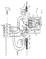
- Apparatus 100 is most suitably mounted within the upper portion of the bulk material container C of a pharmaceutical tablet compression machine as shown in Figure 1, but may alternatively be mounted above or otherwise outside of the bulk material container of the pharmaceutical tablet compression machine as a matter of design choice.
- Automated blend reclaim apparatus 100 comprises a drum 110 , preferably formed of stainless steel, and secured within the top portion of bulk blend container C mounted above a pharmaceutical tablet compression machine.
- a collection apparatus F is provided in drum 110 which comprises a tapered canister 112 , preferably formed from stainless steel, and a cartridge filter 114 mounted in the upper portion of canister 112 .
- An aperture or opening 112A is defined at the bottom of filter canister 112 to facilitate dumping collected blend from filter 114 into bulk material container C in a manner to be described hereinafter.
- a vacuum blower 120 most suitably a SIEMENS brand Part No. ZBH-14170-HK-33Z, is provided at a remote location from canister 112 .
- Hose line 124 is provided to extend from the collection manifold of the tablet compression machine (not shown) to an inlet in canister 112 .
- Hose line 126 is provided to extend from cartridge filter 114 of canister 112 to vacuum blower 120 .
- a compressed air source most suitably an industrial air compressor, is connected to purge accumulator 128 provided adjacent canister 112 and fluidly connected to the proximal end of hose line 126 adjacent canister 112 by conduit 128A .
- control automated blend reclaim apparatus 100 comprising a first valve V1 positioned between bottom aperture 112A of filter canister 112 and an aperture 110A provided at the bottom of drum 110 so as to selectively allow blend from canister 112 to be dumped into bulk material container C of the pharmaceutical tablet compression machine.
- Second pneumatically controlled valve V2 is provided in hose line 124 leading from the vacuum blower 120 to canister 112
- third pneumatically controlled valve V3 is provided in hose line 126 extending from the tablet compression machine to canister 112 .
- a fourth pneumatically controlled valve is provided at the output end of purge accumulator or compressed air source 128 and in fluid communication with conduit 128A .
- valve V1 is hydraulically connected to solenoid dump valve S1 ;
- valve V2 is pneumatically connected to solenoid isolation valve S2 ;
- valve V3 is pneumatically connected to solenoid vacuum valve S3 ;
- valve V4 is pneumatically connected to solenoid purge valve S4 .
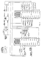
- solenoid valves S1 - S4 are electrically connected to a suitably programmed PLC (programmable logic controller) 140 , most suitably a ALLEN-BRADLEY SLC-5/03 programmable logic controller.
- PLC programmable logic controller
- PLC controller 140 is utilized to control the sequencing of valves V1 - V4 to provide an automated process consisting of (1) an accumulation stage wherein blend material is collected from the vacuum ports through the collection manifold of the tablet compression machine and transported to canister 112 ; and (2) a dump stage wherein after a predetermined period of accumulation the blend is dumped from canister 112 and introduced back into bulk material container C by actuation of compressed air source 128 for a predetermined period of time and subsequent actuation of valve V1 for a predetermined period of time in a manner which will be described in greater detail hereinafter.
- automated blend reclaim apparatus 100 may be operated from a control panel (see Figure 4) which is used by the operator to actuate vacuum blower 120 and PLC 140 .
- a preferred electrical schematic for apparatus 100 is set forth in Figure 3 of the drawings, but applicants contemplate that other electrical circuits are contemplated as within the scope of the invention and would be a matter of design choice by one skilled in the art.
- Automated blend reclaim apparatus 100 is contemplated to utilize automated control by PLC 140 during its intended usage, but a manual control may be provided for manual control of apparatus 100 from time to time at the discretion of the operator.
- apparatus 100 allows for recovery of previously discarded blend which is inherent in manufacturing pharmaceutical tablets with compression machines such as the COURTOY R200.
- compression machines such as the COURTOY R200.
- PLC controlled blend recovery apparatus directly connected to the bulk material container of the tablet compression machine the previously discarded blend can be reintroduced to the tablet compression machine and significant cost savings achieved.
- Apparatus 100 is most suitably mounted within the top portion of bulk material container C but may be mounted above container C if desired.
- container C (known to those skilled in the art as the "BULS Cube") is positioned over the tablet compression machine press and readied for operation.
- Vacuum blower 120 is actuated and PLC 140 is actuated in order to place apparatus 100 under the control of PLC 140 .
- the automated process of apparatus 100 normally consists of two stages.
- the accumulation stage has a preferred duration of about 120 seconds, and during this stage blend is collected from the vacuum ports through the collection manifold of the tablet compression machine and transported to filter F where it is collected on cartridge filter 114 .
- dump valve V1 and purge valve V4 are closed, and vacuum valve V3 and isolation valve V2 are open to allow for vacuum to pull the blend away from the tablet compression machine and into canister 112 .
- purge valve V4 is opened, most suitably for about 1 second, to allow a blast of compressed air to clear the blend off of cartridge filter 114 .
- PLC 140 proceeds to a pause step of the purge/dump stage during which all 4 valves V1 - V4 are closed for about 2 seconds so as to allow purge valve V4 time to close.
- PLC 140 proceeds to the dump step of the dump/purge stage, wherein dump valve V1 is opened, preferably for about 8 seconds, and vacuum valve V3 , isolation valve V2 and purge V4 valve are maintained closed.
- the dump step of the purge/dump stage allows collected blend to empty from filter canister 112 through dump valve V1 and through aperture 110A of drum 110 into bulk material container C .
- PLC 140 returns to the accumulation stage and restarts the cycle.
- blend reclaim system of the present invention could also be used in combination with tablet encapsulation machines, and that this combination is also contemplated by applicants to be within the scope of the invention described and claimed herein.
Landscapes
- Engineering & Computer Science (AREA)
- Mechanical Engineering (AREA)
- Medical Preparation Storing Or Oral Administration Devices (AREA)
- Processing And Handling Of Plastics And Other Materials For Molding In General (AREA)
- Press Drives And Press Lines (AREA)
- Medicines Containing Plant Substances (AREA)
- Medicinal Preparation (AREA)
- Filtering Of Dispersed Particles In Gases (AREA)
Claims (30)
- Automatische Mischungsabfallrückgewinnungseinrichtung in Kombination mit einer Arzneitablettenpreßmaschine, auf welcher ein Schüttmaterialbehälter für die Tablettenmischung angebracht ist, zum erneuten Einführen von Mischungsabfall in die Tablettenpreßmaschine, mit:(a) einem Gehäuse, welches im Betrieb mit dem Schüttmaterialbehälter der Tablettenpreßmaschine verbunden ist, und in dessen Bodenabschnitt eine Öffnung vorgesehen ist;(b) einer in dem Gehäuse und über der Öffnung angebrachten Filtervorrichtung;(c) einer entfernt von dem Gehäuse angeordneten Unterdruckgebläsevorrichtung;(d) einer ersten Leitungsvorrichtung, die von der Tablettenpreßmaschine zu der Filtervorrichtung verläuft;(e) einer zweiten Leitungsvorrichtung, die von der Filtervorrichtung zu der Unterdruckgebläsevorrichtung verläuft;(f) einer Druckluftquellenvorrichtung, die in Fluidverbindung mit der zweiten Leitungsvorrichtung in der Nähe der Filtervorrichtung steht;(g) mehreren Ventilvorrichtungen, die Ventilvorrichtungen umfassen, die zwischen der Filtervorrichtung und der Gehäuseöffnung vorgesehen sind, in der ersten Leitung, in der zweiten Leitung, und im Betrieb der Druckluftquellenvorrichtung zugeordnet sind;(h) einer Steuervorrichtung, die dazu ausgebildet ist, die automatische Mischungsrückgewinnungseinrichtung im Kreislauf zu führen, durch (1) einen Ansammlungsschritt, in welchem die Unterdruckgebläsevorrichtung betätigt wird, und die mehreren Ventilvorrichtungen selektiv so betätigt werden, daß sich Mischung auf der Filtervorrichtung ansammelt; (2) einen Spülschritt, in welchem die mehreren Ventilvorrichtungen selektiv so betätigt werden, daß die Druckluftquellenvorrichtung betätigt wird, und Druckluft von der Druckluftquellenvorrichtung Mischung von der Filtervorrichtung entfernt; und (3) einen Entleerungsschritt, in welchem die mehreren Ventilvorrichtungen selektiv so betätigt werden, daß der entfernte Mischungsabfall dazu veranlaßt wird, von der Filtervorrichtung und durch die Gehäuseöffnung in den Schüttmaterialbehälter der Tablettenpreßmaschine herunterzufallen.
- Kombination nach Anspruch 1, bei welcher das Gehäuse eine zylindrische Trommel aufweist, die ein offenes oberes Ende und ein geschlossenes unteres Ende aufweist, wobei die Öffnung sich in deren unterem Ende befindet.
- Kombination nach Anspruch 2, bei welcher die Trommel aus Edelstahl besteht.
- Kombination nach Anspruch 1, bei welcher die Filtervorrichtung einen sich nach unten erstreckenden Filtergehäuseblechbehälter aufweist, in dessen unterstem Ende eine Öffnung in vertikaler Ausrichtung zur Gehäuseöffnung vorgesehen ist, und einen Kartuschentypfilter aufweist, der innerhalb des Filtergehäuseblechbehälters angebracht ist.
- Kombination nach Anspruch 4, bei welcher der Filtergehäuseblechbehälter aus Edelstahl besteht.
- Kombination nach Anspruch 1, bei welcher die Unterdruckgebläsevorrichtung ein Unterdruckgebläse mit einem Eingang und einem Eingang und einem Ausgang aufweist, und die zweite Leitungsvorrichtung mit dem Eingang verbunden ist, und der Ausgang in Fluidverbindung mit einem Auslaßstaubabscheider steht.
- Kombination nach Anspruch 1, bei welcher die erste Leitungsvorrichtung einen flexiblen Schlauch aufweist, der an einem Ende mit dem Revolverabschnitt der Tablettenpreßmaschine in Fluidverbindung steht, und am anderen Ende mit der Filtervorrichtung.
- Kombination nach Anspruch 1, bei welcher die zweite Leitungsvorrichtung einen flexiblen Schlauch aufweist; der an einem Ende in Fluidverbindung mit der Filtervorrichtung steht, und an dem anderen Ende mit der Unterdruckgebläsevorrichtung.
- Kombination nach Anspruch 1, bei welcher die Druckluftquellenvorrichtung einen Druckluftsammler aufweist, der an eine Druckluftquelle angeschlossen ist.
- Kombination nach Anspruch 1, bei welcher die mehreren Ventilvorrichtungen umfassen:(a) ein erstes Magnetventil, welches in Fluidverbindung mit einem ersten Luftventil steht, welches zwischen der Filtervorrichtung und der Gehäuseöffnung angebracht ist;(b) ein zweites Magnetventil, welches in Fluidverbindung mit einem zweiten Luftventil steht, welches innerhalb der ersten Leitungsvorrichtung angebracht ist;(c) ein drittes Magnetventil, welches in Fluidverbindung mit einem dritten Luftventil steht, welches innerhalb der zweiten Leitungsvorrichtung angebracht ist;(d) ein viertes Magnetventil, welches in Fluidverbindung mit einem vierten Luftventil steht, welches im Betrieb mit der Druckluftquellenvorrichtung verbunden ist.
- Kombination nach Anspruch 1, bei welcher die Steuervorrichtung eine programmierbare Logiksteuerung (PLC) aufweist, um die Abfolge der mehreren Ventilvorrichtungen der Mischungsrückgewinnungseinrichtung zu steuern.
- Kombination nach Anspruch 1, bei welcher der Ansammlungsschritt eine Dauer von etwa 120 Sekunden hat, der Spülschritt eine Dauer von etwa 3 bis 4 Sekunden hat, und der Entleerungsschritt eine Dauer von etwa 8 Sekunden hat.
- Kombination nach Anspruch 1, bei welcher das Gehäuse und die Filtervorrichtung der automatischen Mischungsrückgewinnungseinrichtung in dem oberen Abschnitt des Schüttmaterialbehälters der Tablettenpreßmaschine angebracht sind.
- Kombination nach Anspruch 1, bei welcher das Gehäuse und die Filtervorrichtung der automatischen Mischungsrückgewinnungseinrichtung außerhalb des Schüttmaterialbehälters der Tablettenpreßmaschine angebracht sind.
- Kombination nach Anspruch 1, bei welcher die Tablettenpreßmaschine eine COURTOY R200-Tablettenpreßmaschine ist.
- Automatische Mischungsrückgewinnungseinrichtung in Kombination mit einer Arzneitablettenpreßmaschine, auf welcher ein Schüttmaterialbehälter für die Tablettenmischung angebracht ist, zum erneuten Einführen der Mischung in die Tablettenpreßmaschine, mit:(a) einem Gehäuse, welches in dem oberen Abschnitt des Schüttmaterialbehälters der Tablettenpreßmaschine angebracht ist, und in seinem unteren Abschnitt eine Öffnung aufweist;(b) einer Filtervorrichtung, die in dem Gehäuse und über der Öffnung angebracht ist;(c) einer entfernt von dem Gehäuse angeordneten Unterdruckgebläsevorrichtung;(d) einer ersten Leitungsvorrichtung, die von der Tablettenpreßmaschine zu der Filtervorrichtung verläuft;(e) einer zweiten Leitungsvorrichtung, die von der Filtervorrichtung zu der Unterdruckgebläsevorrichtung verläuft;(f) einer Druckluftquellenvorrichtung, die in Fluidverbindung mit der zweiten Leitungsvorrichtung in der Nähe der Filtervorrichtung steht;(g) mehreren Ventilvorrichtungen, einschließlich Ventilvorrichtungen, die zwischen der Filtervorrichtung und der Gehäuseöffnung vorgesehen sind, in der ersten Leitung, in der zweiten Leitung, und im Betrieb der Druckluftquellenvorrichtung zugeordnet sind;(h) einer Steuervorrichtung, die dazu ausgebildet ist, die automatische Mischungsrückgewinnungseinrichtung im Kreislauf zu führen, durch: (1) einen Ansammlungsschritt, in welchem die Unterdruckgebläsevorrichtung betätigt wird, und die Ventilvorrichtungen in den ersten und zweiten Leitungen geöffnet sind, und die anderen Ventilvorrichtungen geschlossen sind, so daß Mischungsabfall auf der Filtervorrichtung gesammelt wird; (2) einen Spülschritt, in welchem die Druckluftquellenvorrichtung aktiviert wird, und die Ventilvorrichtungen in den ersten und zweiten Leitungen, welche der Druckluftquellenvorrichtung zugeordnet sind, geschlossen sind, so daß ein Druckluftstoß von der Druckluftquellenvorrichtung Mischung von der Filtervorrichtung entfernt; und (3) einen Entleerungsschritt, in welchem die Ventilvorrichtungen, welche der Filtervorrichtung zugeordnet sind, geöffnet sind, und die anderen Filtervorrichtungen geschlossen sind, so daß der entfernte Mischungsabfall von der Filtervorrichtung in den Schüttmaterialbehälter der Tablettenpreßmaschine transportiert wird.
- Kombination nach Anspruch 16, bei welcher das Gehäuse eine zylindrische Trommel aufweist, die ein offenes oberes Ende und ein geschlossenes unteres Ende aufweist, wobei sich die Öffnung in deren unterem Ende befindet.
- Kombination nach Anspruch 17, bei welcher die Trommel aus Edelstahl besteht.
- Kombination nach Anspruch 16, bei welcher die Filtervorrichtung einen sich nach unten erstreckenden Filtergehäuseblechbehälter aufweist, in dessen unterstem Ende eine Öffnung in vertikaler Ausrichtung zu der Gehäuseöffnung vorgesehen ist, sowie ein Kartuschentypfilter, welches innerhalb des Filtergehäuseblechbehälters angebracht ist.
- Kombination nach Anspruch 19, bei welcher der Filtergehäuseblechbehälter aus Edelstahl besteht.
- Kombination nach Anspruch 16, bei welcher die Unterdruckgebläsevorrichtung ein Unterdruckgebläse mit einem Eingang und einem Ausgang aufweist, und die zweite Leitungsvorrichtung mit dem Eingang verbunden ist, und der Ausgang in Fluidverbindung mit einem Auslaßstaubabscheider steht.
- Kombination nach Anspruch 16, bei welcher die erste Leitungsvorrichtung einen flexiblen Schlauch aufweist, der an einem Ende in Fluidverbindung mit dem Revolverabschnitt der Tablettenpreßmaschine steht, und an dem anderen Ende mit der Filtervorrichtung.
- Kombination nach Anspruch 16, bei welcher die zweite Leitungsvorrichtung einen flexiblen Schlauch aufweist, der an einem Ende in Fluidverbindung mit der Filtervorrichtung steht, und an dem anderen Ende mit der Unterdruckgebläsevorrichtung.
- Kombination nach Anspruch 16, bei welcher die Druckluftquellenvorrichtung einen Druckluftsammler aufweist, der an eine Druckluftquelle angeschlossen ist.
- Kombination nach Anspruch 16, bei welcher die mehreren Ventilvorrichtungen aufweisen:(a) ein erstes Magnetventil, welches in Fluidverbindung mit einem ersten Luftventil steht, das zwischen der Filtervorrichtung und der Gehäuseöffnung angebracht ist;(b) ein zweites Magnetventil, welches in Fluidverbindung mit einem zweiten Luftventil steht, das innerhalb der ersten Leitungsvorrichtung angebracht ist;(c) ein drittes Magnetventil, welches in Fluidverbindung mit einem dritten Luftventil steht, das innerhalb der zweiten Leitungsvorrichtung angebracht ist;(d) ein viertes Magnetventil, welches in Fluidverbindung mit einem vierten Luftventil steht, welches im Betrieb mit der Druckluftquellenvorrichtung verbunden ist.
- Kombination nach Anspruch 16, bei welcher die Steuervorrichtung eine programmierbare Logiksteuerung (PLC) aufweist, um die Abfolge der mehreren Ventilvorrichtungen der Mischungsabfallrückgewinnungseinrichtung zu steuern.
- Kombination nach Anspruch 16, bei welcher der Ansammlungsschritt eine Dauer von etwa 120 Sekunden hat, der Spülschritt eine Dauer von etwa 3 bis 4 Sekunden hat, und der Entleerungsschritt eine Dauer von 8 Sekunden hat.
- Kombination nach Anspruch 16, bei welcher die Tablettenpreßmaschine eine COURTOY R200 Tablettenpreßmaschine ist.
- Verfahren zum Recyceln einer Mischung von einer Arzneitablettenpreßmaschine, auf welcher ein Schüttmaterialbehälter für die Tablettenmischung angebracht ist, wobei das Verfahren umfaßt: (1) einen Ansammlungsschritt, in welchem eine Unterdruckgebläsevorrichtung und Ventilvorrichtungen so betätigt werden, daß pneumatisch überschüssige Mischung von der Tablettenpreßmaschine in deren Betrieb entfernt wird, die überschüssige Mischung in einem Luftfluß mitgerissen und in einem Filtersystem gesammelt wird; (2) eine Spülschritt, in welchem eine Druckluftquelle und mehrere Ventilvorrichtungen betätigt werden, und Druckluft von der Druckluftquelle auf das Filtersystem gerichtet wird, um Mischung von dem Filtersystem zu entfernen; und (3) einen Entleerungsschritt, in welchem mehrere Ventilvorrichtungen so betätigt werden, daß die entfernte Mischung dazu veranlaßt wird, aus dem Filtersystem und durch eine Öffnung in dem Gehäuse des Schüttmaterialbehälters der Tablettenpreßmaschine herabzufallen.
- Verfahren nach Anspruch 29, einschließlich Sammeln der überschüssigen Mischung über etwa 120 Sekunden, Entfernen der Mischung von dem Filtersystem über etwa 3 bis 4 Sekunden, und erneutes Einbringen der entfernten Mischung in den Schüttbehälter über etwa 8 Sekunden.
Applications Claiming Priority (3)
| Application Number | Priority Date | Filing Date | Title |
|---|---|---|---|
| US447950 | 1989-12-08 | ||
| US08/447,950 US5667158A (en) | 1995-05-23 | 1995-05-23 | Automated blend reclaim system for pharmaceutical tablet compression machine |
| PCT/US1996/007655 WO1996037360A1 (en) | 1995-05-23 | 1996-05-23 | Automated blend reclaim system for pharmaceutical tablet compression machine |
Publications (2)
| Publication Number | Publication Date |
|---|---|
| EP0827448A1 EP0827448A1 (de) | 1998-03-11 |
| EP0827448B1 true EP0827448B1 (de) | 1999-07-28 |
Family
ID=23778411
Family Applications (1)
| Application Number | Title | Priority Date | Filing Date |
|---|---|---|---|
| EP96916615A Expired - Lifetime EP0827448B1 (de) | 1995-05-23 | 1996-05-23 | Anordnung zur materialrückgewinnung an einer arzneitablettenpresse |
Country Status (9)
| Country | Link |
|---|---|
| US (1) | US5667158A (de) |
| EP (1) | EP0827448B1 (de) |
| JP (1) | JP3188475B2 (de) |
| AT (1) | ATE182517T1 (de) |
| AU (1) | AU721262B2 (de) |
| CA (1) | CA2221459A1 (de) |
| DE (1) | DE69603478T2 (de) |
| ES (1) | ES2134621T3 (de) |
| WO (1) | WO1996037360A1 (de) |
Families Citing this family (7)
| Publication number | Priority date | Publication date | Assignee | Title |
|---|---|---|---|---|
| WO1999061066A2 (en) | 1998-05-27 | 1999-12-02 | Avigen, Inc. | Convection-enhanced delivery of aav vectors |
| US6767200B2 (en) * | 2001-09-28 | 2004-07-27 | Mcneil-Ppc, Inc. | Systems, methods and apparatuses for manufacturing dosage forms |
| DE102005061787A1 (de) * | 2005-12-23 | 2007-06-28 | Fette Gmbh | Vorrichtung zur Erzeugung eines Unterdrucks im abgedichteten Raum einer Tablettenpresse und/oder eines Isolators |
| DE102006035081A1 (de) * | 2006-07-28 | 2008-01-31 | Wacker Chemie Ag | Verfahren und Vorrichtung zur Herstellung von klassiertem polykristallinen Siliciumbruch in hoher Reinheit |
| DE102007041260A1 (de) * | 2007-08-30 | 2009-03-05 | Henkel Ag & Co. Kgaa | Verfahren und Vorrichtung zur Herstellung von Tabletten |
| CN105833952B (zh) * | 2016-03-29 | 2017-12-08 | 泰兴市城东绿化工程有限公司 | 一种节电型大功率煤粉碾磨装置 |
| CN105833957B (zh) * | 2016-03-29 | 2017-12-08 | 泰兴市城东绿化工程有限公司 | 一种旋转型垃圾破碎装置 |
Family Cites Families (11)
| Publication number | Priority date | Publication date | Assignee | Title |
|---|---|---|---|---|
| DE401672C (de) * | 1921-07-17 | 1924-09-09 | Telex Appbau Ges M B H | Aus mehreren Pressen bestehende Anlage zum Brikettieren von Braunkohle |
| US2043086A (en) * | 1934-04-07 | 1936-06-02 | Stokes Machine Co | Tablet compressing machine |
| US3601321A (en) * | 1969-04-14 | 1971-08-24 | Jordan B Barth | Process for preparing granular denture cleanser |
| DD141240A3 (de) * | 1977-08-09 | 1980-04-23 | Peter Goehler | Behaelterschleuse zur ueberfuehrung staubhaltiger und staubfoermiger gueter in ein system hoeheren druckes |
| US4277260A (en) * | 1979-08-14 | 1981-07-07 | Browning Jesse H | Powder collectors |
| GB8302835D0 (en) * | 1983-02-02 | 1983-03-09 | Smith Kline French Lab | Powder recovery apparatus |
| US4823731A (en) * | 1987-02-24 | 1989-04-25 | Howeth David Franklin | Multiple filter/cyclone air filtration apparatus with single, movable filter cleaning system |
| US5002594A (en) * | 1989-08-31 | 1991-03-26 | Ransburg Corporation | Filter pulse-down cartridge cleaning mechanism |
| US5509612A (en) * | 1991-02-11 | 1996-04-23 | Gerteis; Paul | Process and device for the continuous shaping of particulate materials |
| US5261934A (en) * | 1992-03-17 | 1993-11-16 | Nordson Corporation | Powder collection method and apparatus with isolated filter pulsing and compression mounted cartridges |
| JP5743490B2 (ja) | 2010-10-27 | 2015-07-01 | オルガノ株式会社 | 水処理システム及び水処理方法 |
-
1995
- 1995-05-23 US US08/447,950 patent/US5667158A/en not_active Expired - Lifetime
-
1996
- 1996-05-23 DE DE69603478T patent/DE69603478T2/de not_active Expired - Lifetime
- 1996-05-23 WO PCT/US1996/007655 patent/WO1996037360A1/en not_active Ceased
- 1996-05-23 EP EP96916615A patent/EP0827448B1/de not_active Expired - Lifetime
- 1996-05-23 ES ES96916615T patent/ES2134621T3/es not_active Expired - Lifetime
- 1996-05-23 CA CA002221459A patent/CA2221459A1/en not_active Abandoned
- 1996-05-23 AT AT96916615T patent/ATE182517T1/de not_active IP Right Cessation
- 1996-05-23 JP JP53590496A patent/JP3188475B2/ja not_active Expired - Fee Related
- 1996-05-23 AU AU59305/96A patent/AU721262B2/en not_active Ceased
Also Published As
| Publication number | Publication date |
|---|---|
| AU5930596A (en) | 1996-12-11 |
| EP0827448A1 (de) | 1998-03-11 |
| JPH11505751A (ja) | 1999-05-25 |
| DE69603478T2 (de) | 1999-11-25 |
| US5667158A (en) | 1997-09-16 |
| DE69603478D1 (de) | 1999-09-02 |
| CA2221459A1 (en) | 1996-11-28 |
| AU721262B2 (en) | 2000-06-29 |
| MX9708992A (es) | 1998-03-31 |
| JP3188475B2 (ja) | 2001-07-16 |
| WO1996037360A1 (en) | 1996-11-28 |
| ES2134621T3 (es) | 1999-10-01 |
| ATE182517T1 (de) | 1999-08-15 |
Similar Documents
| Publication | Publication Date | Title |
|---|---|---|
| EP0827448B1 (de) | Anordnung zur materialrückgewinnung an einer arzneitablettenpresse | |
| CN101224363B (zh) | 除尘干粉回收工艺 | |
| CA1332750C (en) | Product pump system | |
| EP0686579A2 (de) | Vorrichtung zum getrennten Aufnehmen, Verdichten und Lagern von Hausmüll | |
| CN103406188A (zh) | 全自动破碎研磨一体机 | |
| JP2687311B2 (ja) | 核物質片回収装置 | |
| CN106636507B (zh) | 高炉煤气干法袋式除尘机械式压力卸灰工艺及其装置 | |
| JP2697522B2 (ja) | ゴミ輸送設備 | |
| JP2677578B2 (ja) | 塵芥収集システム及び塵芥収集方法 | |
| MXPA97008992A (en) | Automated system for recovery of mixtures for a pharmaceutical table compression machine | |
| EP1114783B1 (de) | Vorrichtung und Verfahren zum Zerkleinern von Speiseresten | |
| CN210934138U (zh) | 炭板装炭系统 | |
| CN209087184U (zh) | 工业机器人综合技术训练平台 | |
| WO2022132453A1 (en) | Vacuum canister system and method | |
| JPH01252404A (ja) | 塵芥収集システム及び塵芥収集方法 | |
| CN217731995U (zh) | 一种除尘器气力运灰装置 | |
| JPS54100162A (en) | Refuse collecting method and apparatus for the same | |
| CN219441976U (zh) | 用于化工物料的破碎筛分设备 | |
| DE59304411D1 (de) | Verfahren zum Entleeren eines Müllsammelbehälters durch Luftevakuierung | |
| CN213948817U (zh) | 一种包装设备 | |
| JPH06122098A (ja) | 切り屑の圧縮成形装置 | |
| CN213767305U (zh) | 一种危险废物压缩成块装置 | |
| JPH04330981A (ja) | 繊維加工機からの繊維屑の回収移送方法 | |
| CN112169990B (zh) | 一种无尘粉碎工作站及其使用方法 | |
| JP4009769B2 (ja) | 精米施設 |
Legal Events
| Date | Code | Title | Description |
|---|---|---|---|
| PUAI | Public reference made under article 153(3) epc to a published international application that has entered the european phase |
Free format text: ORIGINAL CODE: 0009012 |
|
| 17P | Request for examination filed |
Effective date: 19971112 |
|
| AK | Designated contracting states |
Kind code of ref document: A1 Designated state(s): AT BE CH DE DK ES FI FR GB GR IE IT LI LU MC NL PT SE |
|
| AX | Request for extension of the european patent |
Free format text: AL PAYMENT 971112;LT PAYMENT 971112;LV PAYMENT 971112;SI PAYMENT 971112 |
|
| GRAG | Despatch of communication of intention to grant |
Free format text: ORIGINAL CODE: EPIDOS AGRA |
|
| 17Q | First examination report despatched |
Effective date: 19980904 |
|
| GRAG | Despatch of communication of intention to grant |
Free format text: ORIGINAL CODE: EPIDOS AGRA |
|
| GRAH | Despatch of communication of intention to grant a patent |
Free format text: ORIGINAL CODE: EPIDOS IGRA |
|
| GRAH | Despatch of communication of intention to grant a patent |
Free format text: ORIGINAL CODE: EPIDOS IGRA |
|
| GRAA | (expected) grant |
Free format text: ORIGINAL CODE: 0009210 |
|
| AK | Designated contracting states |
Kind code of ref document: B1 Designated state(s): AT BE CH DE DK ES FI FR GB GR IE IT LI LU MC NL PT SE |
|
| AX | Request for extension of the european patent |
Free format text: AL PAYMENT 19971112;LT PAYMENT 19971112;LV PAYMENT 19971112;SI PAYMENT 19971112 |
|
| LTIE | Lt: invalidation of european patent or patent extension | ||
| PG25 | Lapsed in a contracting state [announced via postgrant information from national office to epo] |
Ref country code: GR Free format text: LAPSE BECAUSE OF NON-PAYMENT OF DUE FEES Effective date: 19990728 |
|
| REF | Corresponds to: |
Ref document number: 182517 Country of ref document: AT Date of ref document: 19990815 Kind code of ref document: T |
|
| REG | Reference to a national code |
Ref country code: CH Ref legal event code: NV Representative=s name: BRAUN & PARTNER PATENT-, MARKEN-, RECHTSANWAELTE Ref country code: CH Ref legal event code: EP |
|
| REF | Corresponds to: |
Ref document number: 69603478 Country of ref document: DE Date of ref document: 19990902 |
|
| ET | Fr: translation filed | ||
| REG | Reference to a national code |
Ref country code: ES Ref legal event code: FG2A Ref document number: 2134621 Country of ref document: ES Kind code of ref document: T3 |
|
| REG | Reference to a national code |
Ref country code: IE Ref legal event code: FG4D |
|
| ITF | It: translation for a ep patent filed | ||
| PG25 | Lapsed in a contracting state [announced via postgrant information from national office to epo] |
Ref country code: PT Free format text: LAPSE BECAUSE OF FAILURE TO SUBMIT A TRANSLATION OF THE DESCRIPTION OR TO PAY THE FEE WITHIN THE PRESCRIBED TIME-LIMIT Effective date: 19991028 Ref country code: DK Free format text: LAPSE BECAUSE OF FAILURE TO SUBMIT A TRANSLATION OF THE DESCRIPTION OR TO PAY THE FEE WITHIN THE PRESCRIBED TIME-LIMIT Effective date: 19991028 |
|
| PG25 | Lapsed in a contracting state [announced via postgrant information from national office to epo] |
Ref country code: LU Free format text: LAPSE BECAUSE OF NON-PAYMENT OF DUE FEES Effective date: 20000523 |
|
| PLBE | No opposition filed within time limit |
Free format text: ORIGINAL CODE: 0009261 |
|
| STAA | Information on the status of an ep patent application or granted ep patent |
Free format text: STATUS: NO OPPOSITION FILED WITHIN TIME LIMIT |
|
| 26N | No opposition filed | ||
| PG25 | Lapsed in a contracting state [announced via postgrant information from national office to epo] |
Ref country code: MC Free format text: LAPSE BECAUSE OF NON-PAYMENT OF DUE FEES Effective date: 20001130 |
|
| REG | Reference to a national code |
Ref country code: GB Ref legal event code: IF02 |
|
| PGFP | Annual fee paid to national office [announced via postgrant information from national office to epo] |
Ref country code: IE Payment date: 20100507 Year of fee payment: 15 Ref country code: FR Payment date: 20100525 Year of fee payment: 15 Ref country code: FI Payment date: 20100503 Year of fee payment: 15 Ref country code: ES Payment date: 20100524 Year of fee payment: 15 |
|
| PGFP | Annual fee paid to national office [announced via postgrant information from national office to epo] |
Ref country code: NL Payment date: 20100510 Year of fee payment: 15 Ref country code: IT Payment date: 20100517 Year of fee payment: 15 Ref country code: DE Payment date: 20100531 Year of fee payment: 15 Ref country code: AT Payment date: 20100407 Year of fee payment: 15 |
|
| PGFP | Annual fee paid to national office [announced via postgrant information from national office to epo] |
Ref country code: CH Payment date: 20100430 Year of fee payment: 15 Ref country code: BE Payment date: 20100603 Year of fee payment: 15 |
|
| PGFP | Annual fee paid to national office [announced via postgrant information from national office to epo] |
Ref country code: SE Payment date: 20100507 Year of fee payment: 15 Ref country code: GB Payment date: 20100401 Year of fee payment: 15 |
|
| BERE | Be: lapsed |
Owner name: *GLAXO WELLCOME INC. Effective date: 20110531 |
|
| REG | Reference to a national code |
Ref country code: DE Ref legal event code: R119 Ref document number: 69603478 Country of ref document: DE |
|
| REG | Reference to a national code |
Ref country code: DE Ref legal event code: R119 Ref document number: 69603478 Country of ref document: DE |
|
| REG | Reference to a national code |
Ref country code: NL Ref legal event code: V1 Effective date: 20111201 |
|
| REG | Reference to a national code |
Ref country code: CH Ref legal event code: PL |
|
| REG | Reference to a national code |
Ref country code: SE Ref legal event code: EUG |
|
| GBPC | Gb: european patent ceased through non-payment of renewal fee |
Effective date: 20110523 |
|
| PG25 | Lapsed in a contracting state [announced via postgrant information from national office to epo] |
Ref country code: NL Free format text: LAPSE BECAUSE OF NON-PAYMENT OF DUE FEES Effective date: 20111201 Ref country code: FI Free format text: LAPSE BECAUSE OF NON-PAYMENT OF DUE FEES Effective date: 20110523 Ref country code: LI Free format text: LAPSE BECAUSE OF NON-PAYMENT OF DUE FEES Effective date: 20110531 Ref country code: CH Free format text: LAPSE BECAUSE OF NON-PAYMENT OF DUE FEES Effective date: 20110531 |
|
| REG | Reference to a national code |
Ref country code: AT Ref legal event code: MM01 Ref document number: 182517 Country of ref document: AT Kind code of ref document: T Effective date: 20110523 |
|
| REG | Reference to a national code |
Ref country code: FR Ref legal event code: ST Effective date: 20120131 |
|
| PG25 | Lapsed in a contracting state [announced via postgrant information from national office to epo] |
Ref country code: IT Free format text: LAPSE BECAUSE OF NON-PAYMENT OF DUE FEES Effective date: 20110523 Ref country code: AT Free format text: LAPSE BECAUSE OF NON-PAYMENT OF DUE FEES Effective date: 20110523 |
|
| REG | Reference to a national code |
Ref country code: IE Ref legal event code: MM4A |
|
| PG25 | Lapsed in a contracting state [announced via postgrant information from national office to epo] |
Ref country code: BE Free format text: LAPSE BECAUSE OF NON-PAYMENT OF DUE FEES Effective date: 20110531 |
|
| PG25 | Lapsed in a contracting state [announced via postgrant information from national office to epo] |
Ref country code: FR Free format text: LAPSE BECAUSE OF NON-PAYMENT OF DUE FEES Effective date: 20110531 Ref country code: IE Free format text: LAPSE BECAUSE OF NON-PAYMENT OF DUE FEES Effective date: 20110523 |
|
| PG25 | Lapsed in a contracting state [announced via postgrant information from national office to epo] |
Ref country code: GB Free format text: LAPSE BECAUSE OF NON-PAYMENT OF DUE FEES Effective date: 20110523 |
|
| PG25 | Lapsed in a contracting state [announced via postgrant information from national office to epo] |
Ref country code: SE Free format text: LAPSE BECAUSE OF NON-PAYMENT OF DUE FEES Effective date: 20110524 |
|
| REG | Reference to a national code |
Ref country code: ES Ref legal event code: FD2A Effective date: 20130604 |
|
| PG25 | Lapsed in a contracting state [announced via postgrant information from national office to epo] |
Ref country code: DE Free format text: LAPSE BECAUSE OF NON-PAYMENT OF DUE FEES Effective date: 20111130 |
|
| PG25 | Lapsed in a contracting state [announced via postgrant information from national office to epo] |
Ref country code: ES Free format text: LAPSE BECAUSE OF NON-PAYMENT OF DUE FEES Effective date: 20110524 |