EP0826827A2 - Rubber insert for covering a cementious railway sleeper and method for installing the rubber insert in a sleeper - Google Patents
Rubber insert for covering a cementious railway sleeper and method for installing the rubber insert in a sleeper Download PDFInfo
- Publication number
- EP0826827A2 EP0826827A2 EP97810597A EP97810597A EP0826827A2 EP 0826827 A2 EP0826827 A2 EP 0826827A2 EP 97810597 A EP97810597 A EP 97810597A EP 97810597 A EP97810597 A EP 97810597A EP 0826827 A2 EP0826827 A2 EP 0826827A2
- Authority
- EP
- European Patent Office
- Prior art keywords
- insert
- rubber
- cement
- threshold
- sleeper
- Prior art date
- Legal status (The legal status is an assumption and is not a legal conclusion. Google has not performed a legal analysis and makes no representation as to the accuracy of the status listed.)
- Withdrawn
Links
Images


Classifications
-
- E—FIXED CONSTRUCTIONS
- E01—CONSTRUCTION OF ROADS, RAILWAYS, OR BRIDGES
- E01B—PERMANENT WAY; PERMANENT-WAY TOOLS; MACHINES FOR MAKING RAILWAYS OF ALL KINDS
- E01B19/00—Protection of permanent way against development of dust or against the effect of wind, sun, frost, or corrosion; Means to reduce development of noise
-
- E—FIXED CONSTRUCTIONS
- E01—CONSTRUCTION OF ROADS, RAILWAYS, OR BRIDGES
- E01B—PERMANENT WAY; PERMANENT-WAY TOOLS; MACHINES FOR MAKING RAILWAYS OF ALL KINDS
- E01B1/00—Ballastway; Other means for supporting the sleepers or the track; Drainage of the ballastway
- E01B1/002—Ballastless track, e.g. concrete slab trackway, or with asphalt layers
- E01B1/005—Ballastless track, e.g. concrete slab trackway, or with asphalt layers with sleeper shoes
-
- E—FIXED CONSTRUCTIONS
- E01—CONSTRUCTION OF ROADS, RAILWAYS, OR BRIDGES
- E01B—PERMANENT WAY; PERMANENT-WAY TOOLS; MACHINES FOR MAKING RAILWAYS OF ALL KINDS
- E01B2204/00—Characteristics of the track and its foundations
- E01B2204/01—Elastic layers other than rail-pads, e.g. sleeper-shoes, bituconcrete
-
- E—FIXED CONSTRUCTIONS
- E01—CONSTRUCTION OF ROADS, RAILWAYS, OR BRIDGES
- E01B—PERMANENT WAY; PERMANENT-WAY TOOLS; MACHINES FOR MAKING RAILWAYS OF ALL KINDS
- E01B2204/00—Characteristics of the track and its foundations
- E01B2204/13—Dowels for slabs, sleepers or rail-fixings
Abstract
Description
Die vorliegende Erfindung betrifft eine Einlage aus Gummi zur Verkleidung
einer Eisenbahnschwelle gemäss dem Oberbegriff des Patentanspruchs 1
sowie ein Verfahren zum Einbau der Einlage gemäss dem Anspruch 7.The present invention relates to a rubber insert for covering
a railway sleeper according to the preamble of
In der Praxis des Eisenbahnbaus, sowie auch in der entsprechenden Patentliteratur, finden heute Einlagen aus Gummi als Verkleidung einer Eisenbahnschwelle aus Zement (bzw. Beton) Anwendung bzw. Erwähnung. Die mit der Gummi-Einlage verkleidete Schwelle wird nach geeigneter Versetzung und Regulierung der Ausrichtung gegenüber einer vorgängig errichteten Unterbau-Ebene aus Zement (Beton), die mittels vertikaler Abstütz- und Einstellstangen und allfälliger horizontalen Einstellstangen erfolgt, und wird sodann mit Zement vergossen, wodurch die Lage der Schwelle, und damit auch jene des Geleises, endgültig festgelegt wird. Die zwischen der Schwelle und dem Zement des Unterbaus vorgesehene Einlage bezweckt, die vom durchfahrenden Zug auf das Umgelände übertragenen Vibrationen zu dämpfen, was eine Reduktion des von vorbeifahrenden Zügen hervorgerufenen Lärms erlaubt sowie eine Reduktion der von den Schienen auf die tragenden Strukturen des Bahnkörpers übertragenen Beanspruchungen.In the practice of railway construction, as well as in the corresponding patent literature, Today, rubber inserts are used to clad a railroad tie from cement (or concrete) application or mention. The one with the Rubber inlay lined threshold will be after appropriate transfer and Regulation of the alignment compared to a previously built substructure level made of cement (concrete) using vertical support and adjustment rods and any horizontal adjustment rods, and is then grouted with cement, causing the location of the threshold, and hence that of the track is finally determined. The one between the threshold and the The cement of the substructure is intended to be used by the passenger Train to dampen vibrations transmitted to the area what allows a reduction in the noise caused by passing trains as well as a reduction from the rails to the supporting structures stresses transmitted to the web.
Beispiele von Lösungen solcher Art sind im Dokument DE-C-1275061 erschöpfend
beschrieben, das dem der hier vorgeschlagenen Einlage aus
Gummi am nächsten kommenden Stand der Technik entspricht, und im Dokument
DE-A-3539225, das das Vorgehen zum Einbauen eines Geleises
betrifft, das dem im Anspruch 7 der vorliegenden Erfindung beanspruchten
Verfahren am nächsten kommt.Examples of solutions of this type are exhaustive in document DE-C-1275061
described that from the deposit proposed here
Rubber corresponds to the closest state of the art, and in the document
DE-A-3539225, the procedure for installing a track
relates to that claimed in
Aus DE-C-1275061 ist ein Eisenbahn-Oberbau mit einer durchgehenden Unterbau-Platte, die den Unterbau bedeckt, und eine Schwelle aufweist, die aus zwei Zementblöcken besteht, die mittels eines in einer Ebene einzementierten Verbindungsträgers verbunden sind, wobei jeder der beiden Zementblöcke mit einer Einlage aus Gummi verkleidet ist. Wird bei einer Schwelle dieser bekannten Art das beispielsweise aus DE-A-3539225 ebenfalls bekannte System des Einbaus übernommen, so müssen gezwungenermassen die Schwelle aus Zement und die sie verkleidende Einlage aus Gummi durchbohrt sein, damit die vertikalen Durchgangsöffnungen für die Gewindestangen für die Abstützung und die Einregulierung geschaffen werden. Diese Technik wird beim Bau moderner Eisenbahnstrecken heute allgemein angewendet, insbesondere für Tunnelstrecken wie beispielsweise der Aermelkanal-Tunnel.DE-C-1275061 describes a railway superstructure with a continuous one Base plate that covers the base and has a threshold that consists of two cement blocks cemented in one level by means of one Connection carrier are connected, each of the two cement blocks is covered with a rubber insert. Will at a threshold this known type is also known, for example, from DE-A-3539225 System of installation adopted, so must be forced the cement threshold and the rubber lining covering it be pierced so that the vertical through openings for the threaded rods for support and regulation. This Technology is generally used in the construction of modern railway lines today, especially for tunnel sections such as the Aermelkanal tunnel.
Ueberigens ist auch zu bemerken, dass es im Rahmen der vorliegenden Erfindung keinerlei Rolle spielt, ob die Schwelle, auf die sich das Geleise abstützt, aus einem einzigen Zementblock besteht, der mit einer einzigen Einlage aus Gummi verkleidet ist, oder aus zwei separaten Zementblöcken, die untereinander durch einen Eisenträger verbunden sind, die je mit einer eigenen Einlage versehen sind, welche Lösungen in der Praxis beide bekannt sind und Anwendung finden. Wichtig ist einzig die Feststellung, dass ein Zementblock, der eine oder beide Schienen des Geleises trägt, mit einer Gummi-Einlage verkleidet ist, eine oder zwei Durchgangsöffnungen für eine oder mehrere verkleidete Abstützstangen aufweist, und mit Zement eingegossen wird, der den Zwischenraum zwischen dem vorgängig erstellten Unterbau und den mit der Gummi-Einlage verkleideten Schwellen ausfüllt.Incidentally, it should also be noted that it is within the scope of the present Invention does not matter whether the threshold is the track supports, consists of a single block of cement with a single Insert is lined with rubber, or from two separate cement blocks, which are connected to each other by an iron beam, each with a own deposit, which solutions in practice both are known and apply. It is only important to state that a cement block that carries one or both rails of the track, with one Rubber insert is lined, one or two through holes for one or has several clad support rods, and with cement is poured in the space between the previous created substructure and the sleepers clad with the rubber insert fills out.
Diese bekannte Art der Gummieinlage zur Verkleidung einer Schwelle bzw. die Art ihres Einbaus vor Ort mittels Vergiessens der Schwelle mit Zement bis zum oberen Rand der Gummi-Einlage weisen immer noch einen wesentlichen Nachteil auf, nämlich dass beim Vergiessen mit Zement der flüssige Zement zwischen dem Zementblock und der Gummi-Einlage eindringen und dadurch eine direkte Verbindung zwischen dem Zementblock und der ebenfalls aus Zement bestehenden Abstützebene des Geleises schaffen kann. Dies geschieht an zwei Stellen der Gummi-Einlage, nämlich an ihrem oberen Rand, der den ganzen Zementblock umgibt, und durch die Vertikalbohrungen hindurch, durch die sich die Gewindestangen erstrecken. Was den oberen Rand der Gummi-Einlage betrifft, die die Form eines länglichen Trogs aufweist, der etwa die untere Hälfte des Schwellen-Blocks aufnimmt, hat das Problem bereits eine Lösung gefunden, indem dieser obere Rand der Einlage mit einer Dichtung in Form einer verformbaren Dichtungslippe oder eines elastischen Dichtungsrings, usw., versehen wird, die den genannten Rand hermetisch abdichten und verhindern, dass selbst sehr flüssiger Zement durchtreten könnte. Andrerseits bleibt das Problem bestehen, dass Zement von unten her durch die Durrchgangsöffnungen für die Gewindestangen eindringen kann. In den bisher bekannten Schwellen bewirkt das Prinzip der kommunizierenden Röhren, dass der flüssige Zement von unten her in die Durchgangsöffnungen eindringt und den ganzen verbleibenden Zwischenraum zwischen der Stange und dem Zementblock ausfüllt, wodurch der Zementblock der Schwelle starr mit der Zementebene des Unterbaus verbunden wird, wodurch jede mit Hilfe der Gummi-Einlage erreichbare Dämpfungswirkung zunichte gemacht wird. Eine solche Dämpfungswirkung ist nur zu erreichen, wenn der Zementblock, auf dem die Schiene befestigt ist, sich unbedingt gegenüber dem Unterbau frei bewegen kann. Jede Behinderung dieser Bewegungsfreiheit ruft eine Einschränkung oder geradezu die Aufhebung des Dämpfungseffektes, so dass trotz einer als Verkleidung eingefügten Gummi-Einlage alle mit der Uebertragung von Lärm und Vibrationen auf den Unterbau verbundenen Probleme erneut auftreten.This known type of rubber insert for covering a threshold or the type of their installation on site by grouting the threshold with cement up to towards the top of the rubber insert still have an essential Disadvantage, namely that when pouring with cement, the liquid cement penetrate between the cement block and the rubber insert and thereby a direct connection between the cement block and the also can create a supporting level of the track made of cement. This happens at two places on the rubber insert, namely at the top Edge that surrounds the whole block of cement and through the vertical holes through which the threaded rods extend. What the The top edge of the rubber insert affects the shape of an elongated trough that holds about the lower half of the threshold block has that Problem already found a solution by this top edge of the insert with a seal in the form of a deformable sealing lip or elastic sealing ring, etc., is provided, the said edge hermetically seal and prevent even very liquid cement could step through. On the other hand, the problem remains that cement penetrate from below through the passage openings for the threaded rods can. In the previously known thresholds, the principle of communicating tubes that the liquid cement from below into the Through holes penetrate and the entire remaining space between the rod and the cement block fills, causing the cement block the threshold rigidly connected to the cement level of the substructure is what any damping effect achievable with the help of the rubber insert is nullified. Such a damping effect is only to reach when the cement block on which the rail is attached, itself can move freely relative to the substructure. Any disability this freedom of movement calls for a restriction or even a lifting of the damping effect, so that despite being inserted as a cladding Rubber insert all with the transmission of noise and vibrations problems associated with the substructure occur again.
Die vorliegende Erfindung setzt sich zum Ziel, die obengenannten Nachteile der Eisenbahnschwelle gemäss dem Stand der Technik auszuschalten und schlägt eine Einlage aus Gummi vor, die die Gewährleistung eines Höchstmasses an Dämpfung der Schwelle unter allen Umständen zu ermöglicht, und die insbesondere verhindert, dass zwischen dem Zementblock der Schwelle und dem ebenfalls aus Zement bestehenden Unterbau irgendeine starre Verbindung infolge Eindringens von Zement zwischen der Einlage und dem Zementblock entstehen könnte.The present invention aims to overcome the above drawbacks switch off the railway sleeper according to the state of the art and proposes an insert made of rubber, which ensures the maximum dimension to allow damping of the threshold under all circumstances, and which, in particular, prevents the Threshold and the substructure, which is also made of cement rigid connection due to the penetration of cement between the insert and the cement block could arise.
Dieses Ziel wird erfüllt mit einer Einlage aus Gummi zur Verkleidung einer
Schwelle gemäss dem charakterisierenden Teil des Patentanspruchs 1.This goal is achieved with a rubber insert for covering one
Threshold according to the characterizing part of
Die Ansprüche 2 bis 6 betreffen sodann weitere bevorzugte Aussführungsvarianten
der erfindungsgemässen Einlage, deren Vorteile im Folgenden für
jeden Fall mit Hilfe bestimmter Ausführungsbeispiele beschrieben werden.
Der Anspruch 7 schliesslich betrifft ein neuartiges Verfahren zum Einbau der
erfindungsgemässen Gummi-Einlage, deren wesentlicher Vorteil darin besteht,
dass die Abstütz- und Einstell- Gewindestangen nach dem Vergiessen
der Schwelle mit der Zementmasse des Unterbaus leicht herausgezogen
werden können.Finally,
Die vorliegende Erfindung wird im Folgenden im Detail unter Bezugnahme auf Ausführungsbeispiele beschrieben, die in den entsprechenden Abbildungen gezeigt sind. Es zeigen:
- Fig. 1
- eine Perspektiv-Ansicht einer Einlage aus Gummi gemäss der vorliegenden Erfindung, die vier Durchgangsöffnungen aufweist zur Aufnahme der Gewindestangen, im Zustand vor dem Einbau im Zementblock der Schwelle,
- Fig. 2
- einen Schnitt längs einer Vertikalebene durch die Schwelle und durch zwei Durchgangsöffnungen für die Gewindestangen, wobei die Schwelle eingebaut und mit Zement mit dem Unterbau aus Zement vergossen gezeigt ist;
- Fig. 3
- eine Einzelheit im Schnitt längs einer Vertikalebene durch die Schwelle und durch eine Durchgangsöffnung für eine Gewindestange, mit einem Rohr, dessen Aussenwand mit elastischen, ringförmigen Leisten versehen ist;
- Fig. 4
- einen dem in der Fig. 3 gezeigten entsprechenden Schnitt mit einer anderen bevorzugten Ausführungsform des erfindungsgemässen Gummirohrs;
- Fig. 5
- einen vergrössert dargestellten Schnitt längs einer Vertikalebene durch eine Gewindestange, und eine bevorzugte Art des Einbaus der Gummi-Einlage mit einem Schutzrohr für die Gewindestange;
Figuren 6 und 7- zwei bevorzugte Anordnungen der Durchgangsbohrungen in einer Einlage gemäss der vorliegenden Erfindung.
- Fig. 1
- 2 shows a perspective view of a rubber insert according to the present invention, which has four through openings for receiving the threaded rods, in the state before installation in the cement block of the sleeper,
- Fig. 2
- a section along a vertical plane through the threshold and through two through openings for the threaded rods, the threshold being installed and shown with cement poured with the cement substructure;
- Fig. 3
- a detail in section along a vertical plane through the threshold and through a through hole for a threaded rod, with a tube, the outer wall of which is provided with elastic, annular strips;
- Fig. 4
- a section corresponding to that shown in FIG. 3 with another preferred embodiment of the rubber tube according to the invention;
- Fig. 5
- an enlarged section along a vertical plane through a threaded rod, and a preferred way of installing the rubber insert with a protective tube for the threaded rod;
- Figures 6 and 7
- two preferred arrangements of the through holes in an insert according to the present invention.
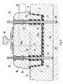
In der Fig. 1 ist eine Perspektiv-Ansicht einer Gummi-Einlage gemäss der
vorliegenden Erfindung dargestellt, genauer gesagt im Zustand wie sie bei
der Herstellung die Form verlässt, also vor dem Einbau in der entsprechenden
Schwelle aus Zement. In dieser Darstellung lassen sich die einzelnen
Partien der Einlage besser unterscheiden, die etwa die allgemeine Form eines
Troges hat, mit einem Boden 1, Seitenwänden 2, 3, 4 und 5, die in der
Regel nach oben leichten Anzug bzw. eine leichte Neigung aufweisen, so
dass sich der Trog gegen die offene Seite hin nach oben erweitert, und mit
einem Verstärkungsrand 6, der alle vier nach oben offenen Seitenwände der
Gummi-Einlage oben umgibt.1 is a perspective view of a rubber insert according to the
Present invention shown, more specifically in the state as in
the manufacturing leaves the form, i.e. before installation in the corresponding
Cement threshold. In this representation, the individual
Differentiate parts of the insert, which are about the general shape of a
Troges has, with a
Hier sei auch bemerkt, dass die nach aussen geneigte Ausbildung der Seitenwände
2 bis 5 der Einlage, die der Einlage eine Trogform geben, deren
oben offener Rand breiter ist als der Boden 1, die bevorzugte Form der Einlage
bilde, im Rahmen der vorliegenden Erfindung unwesentlich ist. Diese
Ausbildungsform bietet gewiss einige praktische Vorteile, wie etwa die leichtere
Ausformbarkeit bei der Herstellung der Einlage und die Erleichterung
des Anbringens der Einlage an der Schwelle aus Zement. Auf jeden Fall bildet
diese, als solche aus der Praxis bekannte Form keine bevorzugte Eigenschaft
der vorliegenden Erfindung, die sich ebenso auf Einlagen aus Gummi
bezieht, die andere Formen aufweisen, beispielsweise mit gegenüber dem
Boden 1 absolut senkrecht stehenden Seitenwänden oder auch ganz andere
geometrische Formen als die hier gezeigte Rechteckform aufweisen.It should also be noted here that the outward inclination of the
Ferner ist bezüglich des Materials, aus dem die Einlage hergestellt wird, hier festzuhalten, dass es sich um Gummi handeln kann, oder um irgend ein anderes elastomeres Material, das geeignet ist die physikalischen und klimatischen Beanspruchungen zu ertragen, die sich aus der besonderen Anwendungsart ergeben, und das in der Praxisanwendung gut bekannt ist. Furthermore, regarding the material from which the insert is made, here to note that it can be rubber or something else elastomeric material that is suitable the physical and climatic To endure stresses resulting from the special type of application result, and that is well known in practice.
Die Einlagen aus Gummi zur Verkleidung von Schwellen aus Zement gemäss dem erwähnten Stand der Technik weisen in ihrem Boden 1 eine oder mehrere (oftmals vier) Bohrungen auf, durch welche, wie im Folgenden unter Bezugnahme auf die Fig. 2 erläutert wird, Gewindestangen durchtreten können, die durch die ganze Schwelle aus Zement reichen und dazu dienen, die Höhenlage der Schwelle einzustellen und sie vor und während des Einbringens des Verguss-Zementes zu verankern.The rubber inlays for covering cement sleepers in accordance with the mentioned prior art have one or several (often four) holes through which, as below 2, threaded rods can pass through, that reach through the whole threshold of cement and serve the Adjust the height of the threshold and set it before and during insertion of the grouting cement.
Die erfindungsgemässe Einlage aus Gummi weist nun, entsprechend der
Durchgangsöffnung im Boden 1 für jede der Abstützstangen (in der Fig. 1
nicht dargestellt), eine kreisförmige Oeffnung 7, 8, 9 und 10 auf (wobei die in
der Fig. 1 dargestellte Einlage für vier Gewindestangen vorgesehen ist, es
könnte jedoch auch nur eine einzige Abstützstange vorgesehen sein), von
der aus sich ein Rohr aus Gummi 11, 12, 13 und 14, gegen den offenen
Rand 6 der Einlage und im wesentlichen bis auf dessen Höhe hin erstreckt,
das zusammen mit dem Boden 1 der Einlage als Einheit ausgebildet ist,
durch welches hindurch die Abstützstange eingeschoben wird.The rubber insert according to the invention now has, according to the
Through opening in the
Die erfindungsgemäse Einlage aus Gummi zeigt also, in ihrem Zustand vor
dem Einbau in die Schwelle, die Form eines Troges, von dessen Boden 1
aus sich integral an diesem angeformte vertikale Rohre 11 bis 14 nach oben
erstrecken.The rubber insert according to the invention thus shows its condition
installation in the threshold, the shape of a trough, from the
Gemäss einer ersten bevorzugten Ausführungsform der vorliegenden Erfindung
besteht das Rohr 11, 12, 13 und 14 aus dem gleichen Material wie die
Einlage und wird durch Einspritzen des Materials in eine geeignete Spritzform
im gleichen Arbeitsgang ausgebildet. Zur leichteren Entnahme der Einlage
aus der Spritzform können die Rohre 11, 12, 13 und 14 mit einem leichten
Anzug ausgebildet werden, so dass sich die Rohre gegen das freie Ende
hin leicht verjüngen. Diese Ausbildungsform ist jedoch im Rahmen der vorliegenden
Erfindung nicht von Bedeutung.According to a first preferred embodiment of the present invention
the
Gemäss einer weiteren bevorzugten Ausführungsform der erfindungsgemässen
Einlage aus Gummi wird das Rohr 11, 12, 13 und 14 mit der Einlage fest
verbunden, indem nachfolgend je eines seiner Enden mittels Vulkanisation
am Rand der entsprechenden, vorgängig im Boden 1 der Gummi-Einlage erstellten
Durchgangsöffnung 7, 8, 9 und 10 fest verbunden wird.According to a further preferred embodiment of the inventive
Rubber insert, the
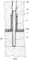
In der Fig. 2 ist die Einlage aus Gummi dargestellt, wie sie sich nach dem vollständigen Einbau der Schwelle nach dem Einbauverfahren mittels Vergiessen des mit der Gummi-Einlage verkleideten Teils der Schwelle zeigt, wie dies in der Praxis gut bekannt ist und beispielsweise in der genannten Schrift DE-C-1275061 beschrieben ist.In Fig. 2, the insert made of rubber is shown as it is after complete installation of the threshold using the paving method shows the part of the threshold clad with the rubber insert, as is well known in practice and for example in the above Document DE-C-1275061 is described.
In der Fig. 2 ist die mit 15 bezeichnete Einlage eine Einheit, bestehend aus
dem Boden 1, den Seitenwänden 2 bis 5 (von denen in der Fig. 2 lediglich
die Wände 2 und 4 sichtbar sind), dem oberen Verstärkungsrand 6 und den
Gummirohren 11 bis 14, die sich vom Boden aus praktisch bis auf die Höhe
des oberen Randes 6 erstrecken. Von diesen Rohren sind in der Fig. 2 lediglich
zwei sichtbar, beispielsweise die beiden Rohre 11 und 12 gemäss der
Fig. 1. In die Einlage 1 aus Gummi ist nun die Schwelle 16 aus Zement eingelassen,
wobei deren unterer Teil 17 ganz in die Einlage 15 eindringt und
deren oberer Teil 18a aus der Einlage 15 hervorsteht eine auf dessen Oberseite
mit bekannten Mitteln befestigte Schiene 18 trägt.In Fig. 2, the
Der untere Teil 17 der Schwelle 15 weist somit entsprechend jedem Gummirohr
11 bis 14 der Gummi-Einlage 15 eine Durchgangsöffnung auf (beispielsweise
19 und 20 gemäss der Fig. 2) die das entsprechende Gummirohr
11 bis 14 aufnimmt. Die Durchgangsöffnung 19, 20 in der Schwelle aus Zement
muss demnach lang genug sein, um das entsprechende Gummirohr 11
bis 14 vollständig aufnehmen zu können, damit gewährleistet ist, dass die
Zementschwelle ganz mit der Gummi-Einlage, und insbesondere mit deren
Boden, in Kontakt kommt. Ein solcher enger Kontakt zwischen der Schwelle
und der Gummi-Einlage ist besonders wichtig, wenn eine gute Dämpfung der
bei Durchfahrt eines Zuges auf den Schienen 18 hervorgerufenen Vibrationen
gewährleistet werden soll. Gegebenenfalls kann, wie in der Fig. 2 gezeigt,
der Boden 1 der Gummi-Einlage 15 innen mit einer Schicht eines anderen
Dämpfungsmaterials ausgekleidet werden, die in der Fig. 2 mit 20a
bezeichnet ist und den Zweck hat, die Dämpfungskapazität der mit Gummi
verkleideten Schwelle zu vergrössern. In der Fig. 2 sind sodann die Abstütz-Gewindestangen
21 und 2 sichtbar, die sich durch den oberen Teil 18a der
Schwelle 16 durch geeignete Durchgangsöffnungen 23, 24 erstrecken, die
mit Büchsen 25, 26 enthalten, die mit einem Innengewinde versehen sind
und in die die Abstützstangen 21 und 22 eingeschraubt werden. Diese Stangen
21 und 22 reichen in den Gummirohren 11 und 12 durch den unteren
Teil 17 der Schwelle 16 hindurch und dringen sodann durch den Zement der
darunterliegenden Zementschicht, die zum "Eingiessen" der Schwelle 16 bis
knapp unter den oberen Rand 6 der Gummi-Einlage 15 eingebracht wird,
nachdem die Schwelle am richtigen Ort versetzt, und mittels der Gewindestangen
21 und 22 abgestützt und in ihrer Höhe einreguliert worden ist. Die
Linie 28 deutet den Unterbau aus Zement an, gegenüber dem die Schwelle
versetzt, festgehalten und einreguliert wird, bevor sie mit dem Füllzement 27
vergossen wird. Aus der Fig. 2 geht auch der Unterschied zwischen der Gewindestange
21 und der Gewindestange 22 hervor: Die Abstützstange 21
dringt mit ihrem unteren Teil in den Zement des Unterbaus 29 ein, während
sich das untere Ende der Stange 22 auf der Oberfläche 28 des Unterbaus 29
abstützt. Dieser Unterschied, der überigens im Rahmen der vorliegenden Erfindung
keinerlei Rolle spielt, weist lediglich auf die unterschiedlichen Funktionen
der beiden Stangen 21 und 22 hin: Während die Stange 22 rein nur
der Einstellung der Höhenlage der Schwelle dient, wobei die Höhenlage
durch Drehen der Stange 22 im Gewinde der Büchse 26 erfolgt, dient die Abstützstange
21, die durch die im vorgängig aus Zement erstellten Unterbau
eingebrachte Bohrung 30 vor dem Vergiessen mit dem Füllzement 27 in den
Unterbau hineingetrieben wird, der Verankerung bzw. Blockierung der Lage
der Schwelle während des Vergiessens der Schwelle mit Zement. Dies entspricht
jedoch ganz dem bekannten Stand der Technik und ist hier nur vollständigkeitshalber
beschrieben.The
Wichtig für die erfindungsgemässen Wirkungen ist jedoch einzig, dass dank
den vorgesehenen Gummirohren 11 bis 14 der Füllzement 27, der zum Vergiessen
sehr dünnflüssig gewählt wird, nicht durch die Oeffnung im Boden 1
der Einlage 15 eindringen und so den Zwischenraum zwischen der Abstützstange
21, 22 und der Schwelle aus Zement ausfüllen kann , wie es der Fall
ist, wenn die Gummirohre 11 bis 14 fehlen, wodurch die Schwelle 16 starr
mit dem Füllzement 27 verbunden wird und der Dämpfungseffekt der Gummi-Einlage
15, die die Schwelle verkleidet, vollständig oder mindestens zu einem
grossen Teil zunichte gemacht wird. In der Tat wird, wenn der dünnflüssige
Zement auch in den Zwischenraum zwischen der Abstützstange 21, 22
und dem zugeordneten Gummirohr 11, 12 eindringen kann, kann dieser Zement
auf keinen Fall eine direkte Verbindung mit dem Zement der Schwelle
schaffen, die im Füllzement 27 höchstens bis zu einer Höhe eingegossen
wird, die -wenn auch nur geringfügig - tiefer liegt als das obere Ende der
Gummirohre 11 bis 14. Wenn also der sehr dünnflüssige Zement gemäss
dem Prinzip der kommunizierenden Röhren zwischen der Abstützstange 21
oder 22 und dem zugeordneten Gummirohr 11 oder 12 bis zu einem höchsten
Niveau eindringen sollte, kann er nicht über das obere Ende des Gummirohrs
11, 12 hinaus ansteigen, das stets auf einem etwas höheren Niveau
liegt als das Niveau, das der Füllzement erreichen kann. Auf diese Weise
wird dank der vorgesehenen Gummirohre 11 bis 14 jede Gefahr gebannt,
dass der Füllzement 27 eine starre Verbindung mit der Schwelle 16 schaffen
könnte, wodurch der ganze, dank der vorgesehenen Einlage 15 aus Gummi
erreichte Dämpfungseffekt zunichte gemacht würde.The only important thing for the effects according to the invention is that thanks
the provided
Die vorliegende Erfindung ist unter Bezugnahme auf die Fig. 2 unter der Annahme
beschrieben, es werde eine Schwelle verwendet, die aus zwei Zementblöcken
besteht (von denen nur der eine, mit 16 bezeichnete sichtbar
ist), die untereinander mittels eines Verbindugsträgers 31 aus Eisen verbunden
sind. Dabei ist klar ersichtlich, dass in gleicher Weise wie oben beschrieben
auch eine einzige durchgehende Schwelle bzw. eine aus einem einzigen
Zementblock bestehende Schwelle, die die beiden Schienen eines
Bahngeleises trägt, verwendet werden kann, und dass auch die Anzahl der
vorgesehenen Abstützstangen mit Gewinde im Rahmen der vorliegenden
Erfindung keinerlei Rolle spielt.The present invention is assumed with reference to FIG. 2
described using a threshold consisting of two blocks of cement
exists (of which only the one marked 16 is visible
is), which are interconnected by means of a connecting
Die Ausbildung des Gummirohrs 11 bis 14, das das wesentliche Element der
vorliegenden Erfindung darstellt, erfährt einige Verbesserungen, die bevorzugte
Lösungen der Erfindung bilden. The formation of the
Eine erste Verbesserung, die im Detail in der Fig. 3 gezeigt ist, besteht darin,
dass die äussere Wandung 32 des Gummirohrs 11 (wobei in den Abbildungen
die gleichen Teile jeweils mit den gleichen Bezugsziffern bezeichnet
werden) mit angeformten, ringförmigen Leisten 33 versehen wird, die sich
spielfrei an die durchbrochene Wand der in der Schwelle 16 eingebrachten
Bohrung 19 anlegt. Auf diese Weise wird das Gummirohr 11 (hier stellvertretend
für alle anderen vorgesehenen Rohre 11 bis 14 gezeigt) zwar in der
Bohrung 19 der Schwelle 16 genau zentriert, die Schwelle 16 kann jedoch
seitliche Bewegungen ausführen, wenn sie unter der Einwirkung der dynamischen
Kräfte steht, die bei Durchfahrt eines Zuges ausgeübt werden. Die
Schwelle 16 hat daher mehr Bewegungsfreiheit gegenüber der Zementfüllung
27, weil die ringförmigen Hohlräume, die sich zwischen der äusseren
Wandung 32 des Gummirohrs 11 und der Wand 34 der Bohrung 19 ausbilden,
der Schwelle erlauben, unter lokaler Verformung der Kämme der ringförmigen
Leisten 33 kleine seitliche Bewegungen auszuführen, die nicht auf
den Füllzement 27 übertragen werden. Somit wird der Effekt der Dämpfung
von Vibrationen bzw. Schwingungen verstärkt.A first improvement, shown in detail in FIG. 3, is to
that the
Gemäss einer weiteren, in der Fig. 4 dargestellten Variante der vorliegenden
Erfindung ist sodann vorgesehen, dass während des Einbringens des Füllzementes
27 jegliches Eindringen des flüssigen Zementes zwischen der Abstützstange
21 und dem Gummirohr 11 verhindert wird, indem die Mündung
35 der Durchgangsöffnung 7, der das Gummirohr 11 (vergleiche mit der Darstellung
in der Fig. 1) zugeordnet ist, durch die sich die Abstützstange 21 erstreckt,
mit einer Dichtung 36 versehen ist, die gegenüber der Abstützstange
21 abdichtet. Der Durchmesser dieses abdichtenden Randes 36, der als einfache
Verdickung des halbkreisförmigen Querschnittes (wie in der Fig. 4 gezeigt)
oder auch in irgendeiner anderen geeigneten Lippenform ausgebildet
sein kann, ist gemäss der Erfindung kleiner als der Innendurchmesser des
Gummirohrs 11 und auch kleiner als der Aussendurchmesser der Abstützstange
21. Dank dieser Auslegung des abdichtenden Randes kann der sehr
dünnflüssige Zement, der wie bereits erwähnt nicht mit dem Zementblock der
Schwelle 16 in Berührung kommen darf (was er erfindungsgemäss schon
wegen des Vorhandenseins des Gummirohrs 11 nicht tun kann), auch nicht
im Zwischenraum zwischen dem Gummirohr 11 und der Abstützstange 21
aufsteigen. Ein solches Ansteigen des Füllzementes, selbst wenn es keine
Gefahr birgt, dass das obere Ende des Rohrs überstiegen wird, würde eine
Versteifung des Rohrs 11 bewirken, das gegenüber der Abstützstange 21
kein Spiel mehr hätte, was eine Verminderung der Dämpfungsfähigkeit der
Anordnung der Schwelle mit der Einlage aus Gummi verursachen würde.
Daher besteht grosses Interesse, die volle Bewegungsfreiheit der Schwelle
16 gegenüber dem Füllzement 27 aufrechtzuerhalten, da die Dämpfungswirkung
der erfindungsgemässen Einlage aus Gummi auf dieser Bewegungsfreiheit
beruht.According to a further variant of the present, shown in FIG. 4
The invention is then provided that during the introduction of the filling
Gemäss einer weiteren bevorzugten Ausführungsform der vorliegenden Erfindung,
die in den Figuren 6 und 7 gezeigt ist, weist die Einlage aus Gummi
zwei Oeffnungen 37, 38 für zwei Abstützstangen (nicht gezeigt) auf, die je mit
dem entsprechenden, am Boden 1 der Einlage angeformten Gummirohr versehen
sind. Die beiden Oeffnungen 37, 38 sind auf je einer Längsseite der
Schwelle angeordnet und von denen eine zur Aufnahme einer Abstütz- und
Befestigungsstange 21 (in der Fig. 2 gezeigt) und die andere zur Aufnahme
einer Abstütz- und Höhenregulierstange 22 (auch in der Fig. 2 gezeigt) dient.According to a further preferred embodiment of the present invention,
which is shown in Figures 6 and 7, has the insert made of rubber
two
Diese Lösung bietet optimale Bedingungen für die Einstellung und die Fixierung jeder einzelnen Schwelle und sieht ein Verfahren zum Einbau der Einlage dieser Art vor, das ein leichtes Herausnehmen der Montagestangen nach dem Giessen der tragenden Zementfüllung 27 erlaubt. Dies ist unter dem Gesichtspunkt der Praxis von grosser Bedeutung, da das Herausnehmen der Abstützstangen auch erlaubt, nötigenfalls und insbesondere im Fall einer Abnützung, z.B. infolge Ermüdung, die Gummi-Einlage als Verkleidung durch neue Einlagen mit vollem Dämpfungsvermögen zu ersetzen.This solution offers optimal conditions for adjustment and fixation every single threshold and sees a procedure for installing the insert this type, which is an easy removal of the mounting bars allowed after pouring the load-bearing cement filling 27. This is under from the point of view of practice of great importance since the removal the support rods also allowed, if necessary and especially in the case wear, e.g. due to fatigue, the rubber insert as a cladding to be replaced by new inserts with full damping capacity.
Die Abstützstangen 21, 22, die direkt im Füllzement 27 eingegossen werden,
neigen dazu, sich darin fest zu verankern, so dass es schwierig oder gar unmöglich
wird, sie zu enffernen.The
Damit dieser Nachteil vermieden werden kann, wie in der Fig. 5 dargestellt, umfasst das neue Verfahren zum Einbau der Gummi-Einlagen in einer Eisenbahnschwelle 16 die folgenden Arbeitsschritte:
- Einfügen der Gummi-Einlagen in
der Zementschwelle 16, Einschieben der Abstützstangen - Versetzen der Einlage/Schwelle-Einheit
mit den Abstützstangen - Vergiessen des Zwischenraums 27 zwischen der Oberfläche 28 des
Unterbaus 29 und dem oberen Rand 6 (Fig. 2) der Gummi-Einlage unter teilweiser Verbindungmit der Schwelle 16,
- Inserting the rubber inserts in the
cement sleeper 16, - Inserting the
support rods - Moving the insert / threshold unit with the
support rods surface 28 of the previously preparedsubstructure 28 made of cement, and adjusting the lateral and vertical position of the insert / threshold unit by means of thesupport rods - Casting the
intermediate space 27 between thesurface 28 of thesubstructure 29 and the upper edge 6 (FIG. 2) of the rubber insert with partial connection to thethreshold 16,
Die Oeffnungen 19, 20 für die Abstützstangen werden sodann nach dem
Ausbau der entsprechenden Stangen 21, 22 oben mittels Plastik-Stopfen
(nicht gezeigt) verschlossen, um das Eindringen von Verunreinigungen zu
verhindern, so dass die Durchgangsöffnungen perfekt sauber bleiben und
jederzeit wieder eine Abstützstange 21 oder 22 aufnehmen können, falls allfällige
Unterhalts- oder Reparaturarbeiten auszuführen sind.The
Die Möglichkeit, die Abstützstangen 21 und 22 aus der Schwelle herauszuziehen,
steht in engem Zusammenhang mit dem Gegenstand der Erfindung,
der Gummirohre 11 bis 14 zum Schutz der Stangen vorsieht. Diese ergeben
einen sehr wichtigen praktischen Vorteil und stellen daher eine besondere
Eigenschaft der vorliegenden Erfindung dar. The possibility of pulling out the
- 11
- Boden der EinlageBottom of the insert
- 22nd
- SeitenwandteilSide wall part
- 33rd
- SeitenwandteilSide wall part
- 44th
- SeitenwandteilSide wall part
- 55
- SeitenwandteilSide wall part
- 66
- VerstärkungsrandReinforcing edge
- 77
- kreisförmige Oeffnungcircular opening
- 88th
- kreisförmige Oeffnungcircular opening
- 99
- kreisförmige Oeffnungcircular opening
- 1010th
- kreisförmige Oeffnungcircular opening
- 1111
- GummirohrRubber tube
- 1212th
- GummirohrRubber tube
- 1313
- GummirohrRubber tube
- 1414
- GummirohrRubber tube
- 1515
- Gummi-EinlageRubber insert
- 1616
- ZementschwelleCement threshold
- 1717th
- Unterer Teil der ZementschwelleLower part of the cement sleeper
- 18a18a
- Oberer Teil der ZementschwelleUpper part of the cement sleeper
- 1818th
- EisenbahnschieneRailroad track
- 1919th
- Durchgangsöffnung im ZementThrough hole in the cement
- 2020th
- Durchgangsöffnung im ZementThrough hole in the cement
- 20a20a
- Schicht aus DämpfungsmaterialLayer of damping material
- 2121
- Abstützstange mit Gewinde Support rod with thread
- 2222
- Abstützstange mit GewindeSupport rod with thread
- 2323
- Durchgangsöffnung durch die SchwelleThrough opening through the threshold
- 2424th
- Durchgangsöffnung durch die SchwelleThrough opening through the threshold
- 2525th
- Büchse mit InnengewindeFemale threaded bush
- 2626
- Büchse mit InnengewindeFemale threaded bush
- 2727
- FüllzementmasseFilling cement paste
- 2828
- Oberfläche des vorgängig erstellten Unterbaus aus ZementSurface of the previously created cement substructure
- 2929
- Unterbau aus ZementSubstructure made of cement
- 3030th
- Bohrungdrilling
- 3131
- VerbindungsträgerConnecting bracket
- 3232
- AussenwandOuter wall
- 3333
- ringförmige Verdickungsleisteannular thickening bar
- 3434
-
Wand der Durchgangsöffnung 20Wall of the
passage opening 20 - 3535
- Mündungmuzzle
- 3636
- abdichtender Dichtungsrandsealing sealing edge
- 3737
- OeffnungOpening
- 3838
- OeffnungOpening
- 3939
- elastisches Schutzrohrelastic protective tube
Claims (7)
dadurch gekennzeichnet, dass
die Gummi-Einlage entsprechend der Durchgangsöffnung (19,20) in ihrem Bodenteil (1) eine runde Oeffnung (7, 8, 9, 10) aufweist, von der aus sich ein am Boden (1) der Einlage angeformtes Gummirohr (11, 12, 13, 14) gegen den offenen Rand (6) der Einlage hin im Wesentlichen bis auf die Höhe dieses Randes erstreckt, und durch das die Abstützstange (21, 22) durchgeschoben wird.Rubber insert for cladding a railway sleeper made of cement, the rubber insert covering at least the lower part of the sleeper, which is poured in with cement when the track is installed, after the sleeper is at the desired height above a previously created cement substructure using at least one the sill has been fixed vertically crossing support rod;
characterized in that
the rubber insert corresponding to the through opening (19, 20) has a round opening (7, 8, 9, 10) in its base part (1), from which a rubber tube (11, 12.) is formed on the base (1) of the insert , 13, 14) extends towards the open edge (6) of the insert essentially up to the height of this edge, and through which the support rod (21, 22) is pushed.
dadurch gekennzeichnet, dass
das Gummirohr (11, 12, 13, 14) aus dem gleichen Material besteht wie die Einlage und im gleichen Spritz-Arbeitsgang zusammen mit ihr in einer geeigneten Form hergestellt wird.Rubber insert according to claim 1,
characterized in that
the rubber tube (11, 12, 13, 14) is made of the same material as the insert and is produced together with it in a suitable form in the same spraying operation.
dadurch gekennzeichnet, dass
das Gummirohr (11, 12, 13, 14) mit der Einlage durch nachfolgendes Vulkanisieren eines seiner Enden an der Leibung der Durchgangsöffnung (7, 8, 9, 10), die vorgängig im Boden (1) der Gummi-Einlage eingebracht wurde, fest verbunden wird. Rubber insert according to claim 1,
characterized in that
the rubber tube (11, 12, 13, 14) with the insert by subsequently vulcanizing one of its ends to the reveal of the through opening (7, 8, 9, 10), which was previously introduced in the bottom (1) of the rubber insert is connected.
dadurch gekennzeichnet, dass
die Aussenwand des Gummirohrs (11 bis 14) mit ringförmigen Verdickungsleisten (33) versehen ist, die sich spielfrei auf die vorgängig erstellte Wand (34) in der Zementschwelle (16) abstützt und das Gummirohr (11 bis 14) in der Durchgangsöffnung (20) der Schwelle (16) zentriert, der Schwelle (16) jedoch erlaubt, unter der Einwirkung der dynamischen Kräfte bei der Durchfahrt eines Zuges auf dem Geleise seitliche Bewegungen auszuführen.Rubber insert according to claim 1,
characterized in that
the outer wall of the rubber tube (11 to 14) is provided with annular thickening strips (33) which are supported without play on the previously created wall (34) in the cement sleeper (16) and the rubber tube (11 to 14) in the through opening (20) the threshold (16) is centered, but the threshold (16) allows lateral movements to be carried out under the influence of the dynamic forces when a train passes through the track.
dadurch gekennzeichnet, dass
die Mündung (35) der Durchgangsöffnung (7) für die Abstützstange (22) eine gegenüber der Abstützstange (22) abdichtende Dichtung (36) aufweist, deren Durchmesser kleiner ist als der Innendurchmesser des Gummirohrs (11) und auch kleiner als der Aussendurchmesser der Abstützstange (22).Rubber insert according to claim 1,
characterized in that
the mouth (35) of the through opening (7) for the support rod (22) has a seal (36) sealing against the support rod (22), the diameter of which is smaller than the inside diameter of the rubber tube (11) and also smaller than the outside diameter of the support rod (22).
dadurch gekennzeichnet, dass
sie zwei Oeffnungen (37, 38) für zwei Abstützstangen aufweist, die je mit dem am Boden (1) der Einlage angeformten Gummirohr versehen ist, und die auf den beiden einander gegenüberliegenden Längsseiten der Schwelle angeordnet sind und von denen die eine als Durchgangsöffnung für eine Abstütz- und Befestigungsstange (21) dient, während die andere als Durchgangsöffnung für eine Abstütz- und Höheneinstellstange (22) für die Schwelle dient. Rubber insert according to claim 1,
characterized in that
it has two openings (37, 38) for two support rods, each of which is provided with the rubber tube formed on the bottom (1) of the insert, and which are arranged on the two opposite longitudinal sides of the threshold and one of which is used as a through opening for one Support and fastening rod (21), while the other serves as a through opening for a support and height adjustment rod (22) for the threshold.
vor dem Einführen der Abstützstangen (21, 22) in die Oeffnungen (19, 20) jede dieser Stangen (21, 22) in ein aussen gerilltes elastisches Schutzrohr (39) eingeschoben wird, das mindestens den nach unten aus der Einlage/Schwelle-Einheit herausragenden Teil der Stange (21, 22) bedeckt, und dass nach Erhärten des Verfüllzementes die Stangen(21, 22) herausgezogen werden, während die elastischen Schutzrohre (39) im Zement verankert bleiben.Method for installing the rubber insert according to claim 1 in a railway sleeper (16), which comprises the following steps:
Before inserting the support rods (21, 22) into the openings (19, 20), each of these rods (21, 22) is inserted into an externally grooved protective tube (39) that at least extends downwards from the insert / threshold unit protruding part of the rod (21, 22) covered, and that after hardening of the backfill cement, the rods (21, 22) are pulled out, while the elastic protective tubes (39) remain anchored in the cement.
Applications Claiming Priority (2)
| Application Number | Priority Date | Filing Date | Title |
|---|---|---|---|
| CH2135/96 | 1996-08-30 | ||
| CH213596A CH691602A5 (en) | 1996-08-30 | 1996-08-30 | Shoe in coating rubber of a concrete sleeper for railway tracks and mounting the rubber shoe in a sleeper. |
Publications (2)
| Publication Number | Publication Date |
|---|---|
| EP0826827A2 true EP0826827A2 (en) | 1998-03-04 |
| EP0826827A3 EP0826827A3 (en) | 1998-11-25 |
Family
ID=4226697
Family Applications (1)
| Application Number | Title | Priority Date | Filing Date |
|---|---|---|---|
| EP97810597A Withdrawn EP0826827A3 (en) | 1996-08-30 | 1997-08-25 | Rubber insert for covering a cementious railway sleeper and method for installing the rubber insert in a sleeper |
Country Status (2)
| Country | Link |
|---|---|
| EP (1) | EP0826827A3 (en) |
| CH (1) | CH691602A5 (en) |
Cited By (5)
| Publication number | Priority date | Publication date | Assignee | Title |
|---|---|---|---|---|
| EP1006239A1 (en) * | 1998-12-04 | 2000-06-07 | Rex Articoli Tecnici SA | Concrete sleeper and sleeper shoe |
| EP1541767A1 (en) * | 2003-12-10 | 2005-06-15 | Patrick Vanhonacker | Railway sleeper |
| DE102009019683A1 (en) | 2009-04-30 | 2010-11-04 | Pahnke, Ulf, Dr.-Ing. | Ballast track, has equalizing layer structured in surface that is turned toward ballast bed such that broken stones are totally or partially taken up and that layer is not plastically and elastically deformable when loaded by rail vehicles |
| KR101184606B1 (en) | 2010-02-02 | 2012-09-21 | 조경호 | Concrete ballast rail accepting dusproof pad having improved structure |
| CN110219212A (en) * | 2019-06-20 | 2019-09-10 | 中铁四院集团岩土工程有限责任公司 | Non-fragment orbit sleeper hangs empty regulation method |
Citations (4)
| Publication number | Priority date | Publication date | Assignee | Title |
|---|---|---|---|---|
| DE1275081B (en) * | 1963-12-12 | 1968-08-14 | Ferroviaires Soc | Railway superstructure with a continuous plate covering the substructure |
| US4652495A (en) * | 1986-01-31 | 1987-03-24 | Japanese National Railways | Resilient coat for tie of direct-connection type track |
| DE3539225A1 (en) * | 1985-11-05 | 1987-05-14 | Max Knape Gmbh & Co Fa | Method of installing a track grid |
| EP0440597A1 (en) * | 1990-01-30 | 1991-08-07 | Allgemeine Baugesellschaft - A. Porr Aktiengesellschaft | Superstructure and substructure of railway bed for rail vehicles |
-
1996
- 1996-08-30 CH CH213596A patent/CH691602A5/en not_active IP Right Cessation
-
1997
- 1997-08-25 EP EP97810597A patent/EP0826827A3/en not_active Withdrawn
Patent Citations (4)
| Publication number | Priority date | Publication date | Assignee | Title |
|---|---|---|---|---|
| DE1275081B (en) * | 1963-12-12 | 1968-08-14 | Ferroviaires Soc | Railway superstructure with a continuous plate covering the substructure |
| DE3539225A1 (en) * | 1985-11-05 | 1987-05-14 | Max Knape Gmbh & Co Fa | Method of installing a track grid |
| US4652495A (en) * | 1986-01-31 | 1987-03-24 | Japanese National Railways | Resilient coat for tie of direct-connection type track |
| EP0440597A1 (en) * | 1990-01-30 | 1991-08-07 | Allgemeine Baugesellschaft - A. Porr Aktiengesellschaft | Superstructure and substructure of railway bed for rail vehicles |
Cited By (6)
| Publication number | Priority date | Publication date | Assignee | Title |
|---|---|---|---|---|
| EP1006239A1 (en) * | 1998-12-04 | 2000-06-07 | Rex Articoli Tecnici SA | Concrete sleeper and sleeper shoe |
| EP1541767A1 (en) * | 2003-12-10 | 2005-06-15 | Patrick Vanhonacker | Railway sleeper |
| BE1015814A5 (en) * | 2003-12-10 | 2005-09-06 | Vanhonacker Patrick | Track railway system installation and traverse to such a system. |
| DE102009019683A1 (en) | 2009-04-30 | 2010-11-04 | Pahnke, Ulf, Dr.-Ing. | Ballast track, has equalizing layer structured in surface that is turned toward ballast bed such that broken stones are totally or partially taken up and that layer is not plastically and elastically deformable when loaded by rail vehicles |
| KR101184606B1 (en) | 2010-02-02 | 2012-09-21 | 조경호 | Concrete ballast rail accepting dusproof pad having improved structure |
| CN110219212A (en) * | 2019-06-20 | 2019-09-10 | 中铁四院集团岩土工程有限责任公司 | Non-fragment orbit sleeper hangs empty regulation method |
Also Published As
| Publication number | Publication date |
|---|---|
| CH691602A5 (en) | 2001-08-31 |
| EP0826827A3 (en) | 1998-11-25 |
Similar Documents
| Publication | Publication Date | Title |
|---|---|---|
| DE3543958A1 (en) | METHOD FOR THE PRODUCTION OF PRESERVED CONCRETE PILLARS AT THE SITE | |
| DE19837360A1 (en) | Installation procedure for a fixed rail track | |
| DE4439894C2 (en) | Track superstructure | |
| EP0826827A2 (en) | Rubber insert for covering a cementious railway sleeper and method for installing the rubber insert in a sleeper | |
| DE10004346C2 (en) | Trouble-free slab track, procedures and sleepers therefor | |
| DE102012009284B4 (en) | Process for the rehabilitation of a solid road / solidified gravel railway | |
| AT411694B (en) | DEVICE FOR THE ELASTIC STORAGE OF A RILLED RAIL | |
| EP0456147B1 (en) | Railwaytrack structure | |
| DE19508108A1 (en) | Double-block concrete railway sleeper | |
| EP3617404B1 (en) | Rail and track structure with the rail | |
| DE10236535B4 (en) | Process for the production of a slab track with the traverse method on bridges and other art structures | |
| DE4325476A1 (en) | Method for producing a substructure for a track for rail vehicles | |
| EP1006239B1 (en) | Concrete sleeper and sleeper shoe | |
| DE2935674A1 (en) | ARRANGEMENT FOR THE CREATION OF AN EDGING PATH NEXT TO THE BULLET BED OF A RAILWAY DAM. | |
| EP1636424B1 (en) | Method for producing a rail track for rail vehicles | |
| DE102004045766B4 (en) | Prefabricated slab and method for producing a solid track with such a precast slab | |
| DE102017131351A1 (en) | Trough-shaped superstructure for a bridge, bridge, prefabricated part for a trough of a bridge and method for the construction of a bridge | |
| CH715209B1 (en) | Track transition unit between a ballast track section and a ballastless track section. | |
| DE3203980C2 (en) | Underpass structure and process for its construction | |
| DE2923153C2 (en) | Holding device for support cheeks to support slope material on an embankment | |
| DE10216573B4 (en) | Method for storing a concrete component and slab track | |
| EP1182294B1 (en) | Railway track and method for making a railway track | |
| DE102004057508A1 (en) | Frame coupling for steel building construction has integral connector with receiver for frame sections and ball joint to allow different orientations of receiver | |
| WO2004018771A1 (en) | Ballastless track and method for the production thereof | |
| DE102015105067B4 (en) | Concrete system for a stable floor |
Legal Events
| Date | Code | Title | Description |
|---|---|---|---|
| PUAI | Public reference made under article 153(3) epc to a published international application that has entered the european phase |
Free format text: ORIGINAL CODE: 0009012 |
|
| AK | Designated contracting states |
Kind code of ref document: A2 Designated state(s): AT CH DE ES FR GB IT LI PT |
|
| AX | Request for extension of the european patent |
Free format text: AL;LT;LV;RO;SI |
|
| PUAL | Search report despatched |
Free format text: ORIGINAL CODE: 0009013 |
|
| AK | Designated contracting states |
Kind code of ref document: A3 Designated state(s): AT BE CH DE DK ES FI FR GB GR IE IT LI LU MC NL PT SE |
|
| AX | Request for extension of the european patent |
Free format text: AL;LT;LV;RO;SI |
|
| 17P | Request for examination filed |
Effective date: 19990520 |
|
| AKX | Designation fees paid |
Free format text: AT CH DE IT LI |
|
| RBV | Designated contracting states (corrected) |
Designated state(s): AT CH DE ES FR GB IT LI PT |
|
| GRAH | Despatch of communication of intention to grant a patent |
Free format text: ORIGINAL CODE: EPIDOS IGRA |
|
| GRAH | Despatch of communication of intention to grant a patent |
Free format text: ORIGINAL CODE: EPIDOS IGRA |
|
| STAA | Information on the status of an ep patent application or granted ep patent |
Free format text: STATUS: THE APPLICATION IS DEEMED TO BE WITHDRAWN |
|
| 18D | Application deemed to be withdrawn |
Effective date: 20030301 |