EP1541767A1 - Railway sleeper - Google Patents
Railway sleeper Download PDFInfo
- Publication number
- EP1541767A1 EP1541767A1 EP04447269A EP04447269A EP1541767A1 EP 1541767 A1 EP1541767 A1 EP 1541767A1 EP 04447269 A EP04447269 A EP 04447269A EP 04447269 A EP04447269 A EP 04447269A EP 1541767 A1 EP1541767 A1 EP 1541767A1
- Authority
- EP
- European Patent Office
- Prior art keywords
- spring
- prestressing
- cross member
- member according
- liner
- Prior art date
- Legal status (The legal status is an assumption and is not a legal conclusion. Google has not performed a legal analysis and makes no representation as to the accuracy of the status listed.)
- Withdrawn
Links
Images


Classifications
-
- E—FIXED CONSTRUCTIONS
- E01—CONSTRUCTION OF ROADS, RAILWAYS, OR BRIDGES
- E01B—PERMANENT WAY; PERMANENT-WAY TOOLS; MACHINES FOR MAKING RAILWAYS OF ALL KINDS
- E01B1/00—Ballastway; Other means for supporting the sleepers or the track; Drainage of the ballastway
- E01B1/002—Ballastless track, e.g. concrete slab trackway, or with asphalt layers
- E01B1/005—Ballastless track, e.g. concrete slab trackway, or with asphalt layers with sleeper shoes
Definitions
- the present invention is in the field of the installation of railways and it particularly relates to a crossbar for the installation of railway tracks.
- Rolling stock traveling on the railway causes two impacts on the rail, the first impact is due to the mass of all vehicles: this is the static load reported on the bogies.
- the second impact is due to the unsprung mass of the bogie: it is this mass that produces the dynamic impulses on the rails and which are transmitted to the environment.
- the dynamic behavior of a railway is determined by the natural frequency of the track, the deflection of the rails to the right of the supports and the damping of the vibrations of the rails.
- the first bending resonance frequency of the wheel / rail assembly is conditioned by the dynamic stiffness of the soles placed under the rails and, where appropriate, by the cushions placed under saddles or crossbars. This resonance frequency is inversely proportional to the antivibration performance of the rail fastening system.
- a low resonant frequency provides better vibration isolation than high resonance frequency.
- Track rails are usually attached to saddles or sleepers with interposition of an elastic or rigid sole and the sleepers can be placed on elastic cushions with possibly protective slippers. Given that the tolerable deflections for the railway are of the order of 3 to 4 mm, the rigidities static and dynamic rails are limited and this has the consequence that the first resonance frequency of known laying systems is above 30 Hz about.
- the present invention aims at simplifying the laying of railways while ensuring a optimization of the acoustic and antivibration insulation of these tracks, in particular the tracks trams, metropolitan, regional express trains (RER), high-speed trains speed (TGV) and other trains.
- tracks trams metropolitan, regional express trains (RER), high-speed trains speed (TGV) and other trains.
- the invention proposes a railway crossing, in which the devices prestressing device to apply a prestressing force to the elastic cushion on which must rest the cross are arranged in housing formed in the cross.
- the prestressing devices are mounted around rods fixed on a base plate in which are formed cubicles for receiving cushions elastic.
- the base plate is dimensioned according to the prestressing to be performed.
- the assembly can be mounted and the preload adjusted at the factory according to the conditions operating the track and the entire crossbar can thus be provided ready to be installed on any support structure without requiring adjustment of the prestressing on the site, which greatly facilitates the installation of the railway.
- the assembly consisting of a rigid block, the prestressing devices, the cushions elastic and the base plate can be placed in a relatively soft liner, semi-rigid or relatively rigid which surrounds the base and the lateral faces of the plate base and a portion of the side faces of the cross.
- the base plate on which the prestressing devices are attached may to be drowned by molding in the bottom of the liner.
- the prestressing devices advantageously consist of active prestressing each comprising a prestress spring or a set integrated two springs with different stiffness and arranged around each other and arranged with retaining means so that each of them acts independently of each other when passing a wheel of a vehicle traveling on the track.
- the prestressing force applied to the elastic supports is adjusted by a adjustable clamping means so that the deflection of the track at the wheels of the vehicles on the track is tolerable under the intended operating conditions.
- the prestressing applied to the elastic supports by the arrangement of the springs maintains the point of functioning of elastic supports in the zone of quasi-linear behavior of its deflection curve.
- the prestressing force becomes very weak during the passage of the wheel and the static deflections of the rail are limited while the anti-vibratory insulation wanted is assured.
- the two-spring active preloading device thus ensures, for rail supports, high apparent static stiffness combined with stiffness weak dynamic.
- the elastic cushions arranged in a cross member according to the invention are advantageously chosen with static and dynamic stiffness such as the first resonant frequency of the wheel / rail / support system is below 30 Hz about. This ensures a more efficient anti-vibration filtration to dampen the waves vibratory towards the environment. It should be noted for comparison that the first resonance frequency of a conventional ballasted track (wheel / rail / ballast system) may vary from 60 to 110 Hz.
- the rails can be fixed in different ways depending on the size or the technique desired in the intended application or the degree of protection of the the environment that the master of the book wants to insure.
- FIG. 1 and 2 An example of railway crossing according to the invention is shown in Figures 1 and 2.
- the crosshead shown by way of example is a bibloc cross type and the drawings show one of the blocks 1 of this cross.
- Such a crossbeam consists of two blocks 1, generally of reinforced concrete, interconnected by a spacer 2 made of steel which extends transversely to the longitudinal direction of the railway, each block being intended to carry a railway track (not shown). It is understood, however, that the invention is also applicable to a cross member of the monobloc type for carrying the two rails of a railway.
- the transom block 1 shown in FIGS. 1 and 2 consists of an assembly comprising a rigid block 11, elastic cushions 12, a base plate 13 and prestress 17 housed in the rigid block and fixed on the base plate so as to apply an adjustable prestressing stress on the elastic cushions.
- the base plate 13 is itself disposed on the bottom of a soft liner 14 or semi-rigid which surrounds the base and the lateral faces of the base plate 13 and a part of the lateral faces of the rigid block 11.
- the rigid block 11 here has faces sideways that converge each other upwards. It has four vertical openings 16 crossing the rigid block from one side to the other and each serving active preloading device 17.
- a single prestressing device is shown schematically in Figure 2.
- Each active prestressing device is mounted around a rod 15 fixed at its lower end to the base plate 13. Active preloading devices are described in detail later.
- the length of the stems 15 depends on the height of the crossbar.
- a cap of protection 18 covers the opening of the housing 16 of each prestressing device active.
- the base plate is made of steel, synthetic material or other. Its dimensions are chosen according to the prestressing to be applied to the elastic cushions. She is shown in particular in Figures 3 and 4 on which we see four cubicles 22 each receiving an elastic cushion 12 and four threaded rods 15 are also seen which extend substantially vertically above the baseplate and serve mounting four active prestressing devices 17 in the housings provided for this effect in the rigid block 11 above.
- Reference sign 21 designates orifices intended the evacuation of air and water eventually.
- the elastic cushions 12 have dimensions chosen according to the natural frequency of the track and static rigidities and appropriate dynamics to achieve the desired antivibration performance in taking into account the expected axle loads.
- the elastic cushions are advantageously chosen with static and dynamic stiffness such as the first resonant frequency of the wheel / rail / support system is below 30 Hz about. This ensures a more efficient anti-vibration filtration to dampen the waves vibratory towards the environment.
- the first frequency of resonance of a conventional ballasted track can range from 60 to 110 Hz.
- the base plate promotes the uniform loading of the elastic cushions during of the passage of a car on the rails and improves their antivibration behavior.
- the vibrations of the rail during the passage of a car on the rails are thus damped into a very short time, which avoids the production of resonances between the rails and the cars, which are not only inconvenient for the comfort of travelers but are also harmful to the rolling stock and the stability of the rails.
- the prestressing devices are therefore integrated in the sleepers and the prestressing can thus be set in the factory according to the operating conditions of the way to be installed so that the whole can be so provided ready to be installed on any support structure without any further need for adjustment of the prestressing on the site, which considerably facilitates the installation of the track.
- Active prestressing devices are advantageously devices comprising each at least one preload spring with adjustable clamping means.
- prestressing device 17 comprises an integrated assembly of two springs 31 and 33 mounted around a rod 15 fixed to the base plate.
- the first spring 31 is chosen with a lower rigidity than that of the second spring 33 which is arranged around the first.
- the spring 31 is shorter than the spring 33 and its lower end rests on a support washer 32. Its upper end supports a cap 34 serving the spring return movement of greater rigidity.
- the cap 34 supports the end lower end of the spring 33.
- the upper end of the spring 33 cooperates with a washer of isolated abutment 36 which, in turn, cooperates with a tightening nut 37 screwed onto the end threaded rod 15.
- the insulated washer 36 provides additional insulation for a frequency range.
- the circular ring 38 disposed around the stem 15 limits the Lateral movement of the crossbar relative to the boot.
- a protective cap 18 covers the opening of the housing 16 of each prestressing device.
- the prestressing force applied to the elastic cushions 12 is adjusted by means of the nut 37.
- the two springs act independently of one another.
- the spring 33 is completely free prestressing and it does not contribute to the dynamic stiffness of the wheel + rail + assembly fastening system. Only the spring 31 applies a low prestressing force when a wheel goes on the rail.
- FIG. 7 shows an alternative embodiment of the active prestressing device described more above.
- This embodiment differs from that of FIG. 6 in that the washer of support 32 has a double shoulder instead of a cap pressing on the first spring 31.
- the support washer 32 supports the lower end of the spring 33, the upper shoulder of the washer supporting the spring 31.
- the lower surface of the thrust washer 36 has a shoulder 35 which cooperates with the upper end 31.
- the spring 33 is free when the wheels of a vehicle on the track.
- This embodiment makes it possible to have a smaller diameter for the arrangement of the two springs.
- the railway crossing according to the invention above by way of example thus comprises active prestressing devices each having two elastic stages with springs.
- this active prestressing device is set so that applied to the elastic cushions 12 a significant prestressing (of the order of 10 kN) and this prestress is chosen so that the elastic cushions work continuously in the quasi-linear zone of their deflection curve. Indeed, since the actual load applied to a rail support when passing a wheel on the rail is almost static and fast, it is important to avoid the point of functioning of the elastic cushions 12 does not pass each time in the non-linear zone of their deflection curve.
- stiffness static and dynamic such as successive supports along the railway line are alternatively relatively rigid support and relatively flexible support.
- the alternation of stiffness along the track ensures a resonance frequency lower than with a conventional system with uniform stiffness. It results in improved damping of shock waves, reduced vibration transmitted in the soil, a limitation of the static deflection of the rails during the passage of wheels and a shorter flexion of the rails, which leads to a reduction of the radiation acoustic.
- a railway In order to obtain effective vibration damping insulation, a railway shall be constructed in such a way that the static stiffness of an elastic cushion is less than 5 ⁇ 10 6 N / m and its dynamic stiffness is less than 7 ⁇ 10 6 N / m. It is also necessary that the deflection of the track during the passage of the wheels of a vehicle is limited to a value of the order of 3 to 4 mm.
- the distance between sleepers and the static stiffness of the supports are adapted according to the loads and the type of rail used.
- the acoustic and vibration isolation performance of a railway line fixed on sleepers according to the invention are linked to an optimum combination of characteristics elements involved in the production of anti-vibration devices.
- An advantage of the cross member according to the invention is that the performance of acoustic insulation and anti-vibration intended for a railway installation can be adjusted at the factory, this which significantly reduces the installation time of a railway and the cost of this installation.
- the realization of a sleeper according to the invention is therefore based on the technical study of the layout of the railway at the level of vibration impact on the environment and surrounding structures.
- the dynamic rigidity to be obtained is determined.
- the choice of the product for the elastic cushions 12 is based on its static and dynamic characteristics and the dimensions of the elastic cushions.
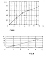
- the deformations of the elastic cushion are recorded for different axle load ratios and, on the load curve, a minimum load rate and a maximum load ratio are selected. For example, on the load curve of Figure 8 we see that a minimum load rate of 0.25 N / mm 2 gives a deflection of 5.5 mm and a maximum load rate of 0, 3 N / mm 2 gives a deflection of 7.5 mm.
- the prestressing is then adjusted so as to reduce the deflection of the elastic cushions so as to limit the deflection of the railway to a value of between 3 and 4 mm, for example during the passage of a vehicle wheel.
- the prestress is applied by the spring 33 and is adjusted by the clamping nut 37.
- the dynamic stiffness of the spring 33 is thus determined as a function of the force of the force. prestressing to achieve.
- axle loads between 100 kN and 120 kN and deflections of 5.5 mm and 7.5 mm obtained with elastic cushions 12 having an area of about 100,000 mm 2
- the preload applied must therefore correspond to a load producing a deflection of between 2.5 mm and 4.5 mm.
- a prestressing loading rate of 0.15 N / mm 2 produces a compression of 1 mm.
- This prestressing is quite satisfactory because, during the passage of the wheels of a vehicle, the spring 33 is decoupled and it no longer intervenes in the dynamic rigidity of the support system.
- This active prestressing device thus ensures optimal operating conditions on anti-vibration supports, that is to say a very low dynamic stiffness while limiting the deflection of the rails that it is intended to fix on the sleepers to the value tolerated about 3 mm for example.
- the following set the invention is disposed on the bottom of a boot 14 which envelops the base and the faces lateral portions of the base plate 13 and a portion of the lateral faces of the rigid block 11.
- Slipper can be realized in different modes of execution. It can be realized with a any profile chosen according to the cross and in order to ensure the best possible tightening around the crossbar while allowing easy introduction of the cross and easy removal of the cross for replacement or maintenance.
- the slipper is made of a relatively soft, semi-rigid or relatively rigid material, by example an elastomer, the dynamic stiffness of the liner is chosen to be greater than that of the elastic supports of the crossbar.
- the hanging of the side walls at the transom is by any means, for example by strapping.
- the liner 14 comprises a bottom 23 and a side wall 24 which is connected to the bottom 23 and is folded virtually vertically.
- the side wall is shaped so that only its upper part encloses the rigid block 11.
- the tightening is performed by a surface of relatively reduced peripheral contact at the end of the side wall. This decreases the friction between the body of the transom and the slipper and facilitates the introduction and extraction of the body of the cross.
- a peripheral bead 13 retained in a notch 26 formed in the inner surface of the side wall 24 of the slipper.
- the peripheral cord 27 has a predetermined dynamic stiffness and improves the lateral and vertical damping rate of the vibrations of the rigid block of the crossbar.
- This The peripheral cord 27 is advantageously made of an elastic material.
- the surface outer wall of the side wall 24 of the liner has a groove 28 arranged to receive a flange or ribbon 29 providing a peripheral strapping of the liner.
- the circumferential strapping reinforces the tightening of the slipper on the rigid block of the crossbar the along the outer edge of the liner and increases the tightness of the device while leaving the body of the crossbar enough freedom to promote the damping of vibrations.
- the ribbon 29 also allows the immediate identification of the slipper, in particular as to the nature of the elastic supports incorporated in the transom. This is a great importance in laying systems with alternating dynamic stiffness along the track.
- Fig. 10 illustrates an alternative embodiment in which the base plate 13 of Figure 1 is embedded by molding in the bottom 23 of the liner 14.
- the base plate door threaded pins 19 which emerge from the upper face of the bottom of the shoe and on which are fixed the rods 15 around which are mounted the devices of prestressing.
- the active prestressing devices housed in the rigid block 11 have been described above.
Landscapes
- Engineering & Computer Science (AREA)
- Architecture (AREA)
- Civil Engineering (AREA)
- Structural Engineering (AREA)
- Vibration Prevention Devices (AREA)
- Railway Tracks (AREA)
Abstract
Description
La présente invention s'inscrit dans le domaine de l'installation de voies ferrées et elle concerne en particulier une traverse pour l'installation de rails de voie ferrée.The present invention is in the field of the installation of railways and it particularly relates to a crossbar for the installation of railway tracks.
L'exploitation de voies ferrées pose un problème qui se situe à quatre niveaux :
Le matériel roulant circulant sur la voie ferrée provoque deux impacts sur le rail, Le premier impact est dû à la masse de l'ensemble des véhicules : c'est la charge statique reportée sur les bogies. Le second impact est dû à la masse non suspendue du bogie : c'est cette masse qui produit les impulsions dynamiques sur les rails et qui se transmettent vers l'environnement.Rolling stock traveling on the railway causes two impacts on the rail, the first impact is due to the mass of all vehicles: this is the static load reported on the bogies. The second impact is due to the unsprung mass of the bogie: it is this mass that produces the dynamic impulses on the rails and which are transmitted to the environment.
Globalement, les phénomènes acoustiques et vibratoires qui prennent naissance lors du
passage d'une rame sur les supports des rails comprennent plusieurs composantes parmi
lesquelles on peut citer :
Le comportement dynamique d'une voie ferrée est déterminé par la fréquence propre de la voie, la déflexion des rails au droit des supports et l'amortissement des vibrations des rails. La première fréquence de résonance en flexion de l'ensemble roue/rail est conditionnée par la raideur dynamique des semelles placées sous les rails et, le cas échéant, par celle des coussins placés sous les selles ou les traverses. Cette fréquence de résonance est inversement proportionnelle à la performance antivibratoire du système de fixation des rails. Une fréquence de résonance basse assure une meilleure isolation antivibratoire qu'une fréquence de résonance élevée. Cependant, il y a une limite physique inférieure en dessous de laquelle ne peut descendre la raideur dynamique des semelles antivibratoires utilisées car la raideur dynamique de ces semelles est en relation directe avec leur raideur statique et leur raideur statique ne peut être trop faible car elle influence directement la déflexion des rails lors du passage d'un véhicule sur les rails.The dynamic behavior of a railway is determined by the natural frequency of the track, the deflection of the rails to the right of the supports and the damping of the vibrations of the rails. The first bending resonance frequency of the wheel / rail assembly is conditioned by the dynamic stiffness of the soles placed under the rails and, where appropriate, by the cushions placed under saddles or crossbars. This resonance frequency is inversely proportional to the antivibration performance of the rail fastening system. A low resonant frequency provides better vibration isolation than high resonance frequency. However, there is a lower physical limit in below which can not come down the dynamic stiffness of the antivibration soles used because the dynamic stiffness of these soles is directly related to their stiffness static and their static stiffness can not be too weak because it directly influences the deflection of the rails during the passage of a vehicle on the rails.
Les rails de voie ferrée sont habituellement fixés sur des selles ou sur des traverses avec interposition d'une semelle élastique ou rigide et les traverses peuvent être posées sur des coussins élastiques avec éventuellement des chaussons de protection . Etant donné que les déflexions tolérables pour la voie ferrée sont de l'ordre de 3 à 4 mm environ, les rigidités statiques et dynamiques des rails sont limitées et ceci a pour conséquence que la première fréquence de résonance des systèmes de pose connus est située au-dessus de 30 Hz environ.Track rails are usually attached to saddles or sleepers with interposition of an elastic or rigid sole and the sleepers can be placed on elastic cushions with possibly protective slippers. Given that the tolerable deflections for the railway are of the order of 3 to 4 mm, the rigidities static and dynamic rails are limited and this has the consequence that the first resonance frequency of known laying systems is above 30 Hz about.
Pour limiter la déflexion des rails de voie ferrée au passage des roues d'un véhicule circulant sur la voie, il est connu d'appliquer une précontrainte aux coussins élastiques placées sous les traverses. Afin d'obtenir des performances d'isolation antivibratoire optimales, la précontrainte à appliquer doit être ajustée de manière aussi précise que possible en tenant compte des conditions d'exploitation de la voie ferrée, des caractéristiques des éléments utilisés pour les appuis antivibratoires et des caractéristiques des rails eux-mêmes. Le réglage de cette précontrainte sur le site est laborieux et allonge considérablement le temps d'installation d'une voie ferrée et par conséquent le coût de cette installation.To limit the deflection of railway tracks to the passage of the wheels of a vehicle circulating on the track, it is known to apply a prestressing to the elastic cushions placed under the sleepers. In order to obtain vibration isolation performance optimal, the prestressing to be applied must be adjusted as precisely as possible taking into account the operating conditions of the railway, characteristics of the elements used for the antivibration supports and characteristics rails themselves. The adjustment of this prestressing on the site is laborious and lengthens considerably the installation time of a railway line and consequently the cost of this installation.
La présente invention vise à simplifier la pose de voies ferrées tout en assurant une optimisation de l'isolation acoustique et antivibratoire de ces voies, notamment les voies ferrées pour tramways, métropolitain, trains express régionaux (RER), trains à grande vitesse (TGV) et autres trains.The present invention aims at simplifying the laying of railways while ensuring a optimization of the acoustic and antivibration insulation of these tracks, in particular the tracks trams, metropolitan, regional express trains (RER), high-speed trains speed (TGV) and other trains.
A cet effet, l'invention propose une traverse pour voie ferrée, dans laquelle les dispositifs de précontrainte devant appliquer un effort de précontrainte au coussin élastique sur lequel doit reposer la traverse sont disposés dans des logements formés dans la traverse. Dans ces logements, les dispositifs de précontrainte sont montés autour de tiges fixées sur une plaque de base dans laquelle sont ménagés des logettes pour recevoir des coussins élastiques. La plaque de base est dimensionnée en fonction de la précontrainte à réaliser. L'ensemble peut être monté et la précontrainte réglée en usine d'après les conditions d'exploitation de la voie et l'ensemble de la traverse peut ainsi être fourni prêt à être installé sur une structure de support quelconque sans nécessiter de réglage de la précontrainte sur le site, ce qui facilite considérablement l'installation de la voie ferrée.For this purpose, the invention proposes a railway crossing, in which the devices prestressing device to apply a prestressing force to the elastic cushion on which must rest the cross are arranged in housing formed in the cross. In these housings, the prestressing devices are mounted around rods fixed on a base plate in which are formed cubicles for receiving cushions elastic. The base plate is dimensioned according to the prestressing to be performed. The assembly can be mounted and the preload adjusted at the factory according to the conditions operating the track and the entire crossbar can thus be provided ready to be installed on any support structure without requiring adjustment of the prestressing on the site, which greatly facilitates the installation of the railway.
L'ensemble constitué par un bloc rigide, les dispositifs de précontrainte, les coussins élastiques et la plaque de base peut être placé dans un chausson relativement souple, semi-rigide ou relativement rigide qui enveloppe la base et les faces latérales de la plaque de base ainsi qu'une partie des faces latérales de la traverse. Dans une variante de mode d'exécution, la plaque de base sur laquelle sont fixés les dispositifs de précontrainte peut être noyée par moulage dans le fond du chausson.The assembly consisting of a rigid block, the prestressing devices, the cushions elastic and the base plate can be placed in a relatively soft liner, semi-rigid or relatively rigid which surrounds the base and the lateral faces of the plate base and a portion of the side faces of the cross. In a fashion variant of execution, the base plate on which the prestressing devices are attached may to be drowned by molding in the bottom of the liner.
Les dispositifs de précontrainte sont avantageusement constitués de dispositifs de précontrainte active comprenant chacun un ressort de précontrainte ou un ensemble intégré de deux ressorts ayant des raideurs différentes et disposés l'un autour de l'autre et agencés avec des moyens de retenue de manière que chacun d'eux agisse indépendamment l'un de l'autre lors du passage d'une roue d'un véhicule circulant sur la voie ferrée. L'effort de précontrainte appliqué aux appuis élastiques est ajusté par un moyen de serrage réglable en sorte que la déflexion de la voie au passage des roues des véhicules circulant sur la voie soit tolérable dans les conditions d'exploitation prévues.The prestressing devices advantageously consist of active prestressing each comprising a prestress spring or a set integrated two springs with different stiffness and arranged around each other and arranged with retaining means so that each of them acts independently of each other when passing a wheel of a vehicle traveling on the track. The prestressing force applied to the elastic supports is adjusted by a adjustable clamping means so that the deflection of the track at the wheels of the vehicles on the track is tolerable under the intended operating conditions.
Lorsqu'une roue passe sur le rail au-dessus d'un dispositif de fixation, la précontrainte appliquée aux appuis élastiques par l'agencement des ressorts maintient le point de fonctionnement des appuis élastiques dans la zone de comportement quasi-linéaire de sa courbe de déflexion. L'effort de précontrainte devient très faible lors du passage de la roue et les déflexions statiques du rail se trouvent limitées tandis que l'isolation anti-vibratoire voulue est assurée. Le dispositif de précontrainte active à deux ressorts assure ainsi, pour les appuis du rail, une raideur statique apparente élevée combinée à une raideur dynamique faible.When a wheel passes over the rail above a fastener, the prestressing applied to the elastic supports by the arrangement of the springs maintains the point of functioning of elastic supports in the zone of quasi-linear behavior of its deflection curve. The prestressing force becomes very weak during the passage of the wheel and the static deflections of the rail are limited while the anti-vibratory insulation wanted is assured. The two-spring active preloading device thus ensures, for rail supports, high apparent static stiffness combined with stiffness weak dynamic.
Les coussins élastiques disposés dans une traverse suivant l'invention sont avantageusement choisis avec des raideurs statiques et dynamiques telles que la première fréquence de résonance du système roue / rail / support soit située en dessous de 30 Hz environ. Ceci assure une filtration anti-vibratoire plus performante pour amortir les ondes vibratoires vers l'environnement. On notera à titre de comparaison que la première fréquence de résonance d'une voie ballastée classique (système roue / rail / ballast) peut varier de 60 à 110 Hz.The elastic cushions arranged in a cross member according to the invention are advantageously chosen with static and dynamic stiffness such as the first resonant frequency of the wheel / rail / support system is below 30 Hz about. This ensures a more efficient anti-vibration filtration to dampen the waves vibratory towards the environment. It should be noted for comparison that the first resonance frequency of a conventional ballasted track (wheel / rail / ballast system) may vary from 60 to 110 Hz.
Les rails peuvent être fixés de différentes manières selon l'encombrement ou la technique souhaitée dans l'application envisagée ou encore selon le degré de protection de l'environnement que le maítre de l'ouvrage veut assurer.The rails can be fixed in different ways depending on the size or the technique desired in the intended application or the degree of protection of the the environment that the master of the book wants to insure.
Un exemple de mode de réalisation de l'invention est décrit dans ce qui suit à l'aide des dessins joints.
- La figure 1
- est une vue en plan d'un bloc de traverse de voie ferrée suivant l'invention;
- La figure 2
- montre une vue en élévation avec coupe longitudinale partielle suivant la ligne II-II de la figure 1;
- La figure 3
- est une vue en plan de la plaque de base montrée sur la figure 2;
- La figure 4
- est une vue en coupe suivant la ligne IV-IV de la figure 3 ;
- La figure 5
- illustre en coupe un exemple de mode de réalisation avantageux pour le chausson enveloppant partiellement une traverse suivant l'invention ;
- La figure 6
- montre une vue agrandie d'un exemple de mode d'exécution du dispositif de précontrainte intégré dans la traverse de la figure 2;
- La figure 7
- illustre une variante d'exécution du dispositif de précontrainte représenté à titre d'exemple à la figure 6 ;
- La figure 8
- montre un exemple de courbe de mise en charge d'un coussin élastique ;
- La figure 9
- est un diagramme montrant la compression d'un exemple de ressort en fonction du taux de charge appliqué ;
- La figure 10
- est une vue en coupe de la partie inférieure d'un bloc de traverse suivant l'invention, dans laquelle la plaque de base se trouve noyée par moulage dans le fond du chausson enveloppant partiellement le bloc de traverse ;
- Figure 1
- is a plan view of a railroad tie block according to the invention;
- Figure 2
- shows an elevational view with partial longitudinal section along the line II-II of Figure 1;
- Figure 3
- is a plan view of the base plate shown in Figure 2;
- Figure 4
- is a sectional view along the line IV-IV of Figure 3;
- Figure 5
- illustrates in section an exemplary advantageous embodiment for the liner partially enclosing a cross member according to the invention;
- Figure 6
- shows an enlarged view of an exemplary embodiment of the prestressing device integrated in the cross member of Figure 2;
- Figure 7
- illustrates an alternative embodiment of the prestressing device shown by way of example in Figure 6;
- Figure 8
- shows an example of loading curve of an elastic cushion;
- Figure 9
- is a diagram showing the compression of an example of a spring as a function of the applied load rate;
- Figure 10
- is a sectional view of the lower part of a crossbar block according to the invention, wherein the base plate is embedded by molding in the bottom of the liner partially enveloping the cross block;
Dans les dessins, un même signe de référence désigne un élément identique ou un élément similaire ou équivalent. Les modes d'exécution illustrés dans ces dessins sont donnés à titre d'exemples non limitatifs.In the drawings, the same reference sign designates an identical element or a similar element or equivalent. The execution modes illustrated in these drawings are given as non-limiting examples.
Un exemple de traverse de voie ferrée suivant l'invention est représenté aux figures 1 et 2.
La traverse illustrée à titre d'exemple est une traverse du type bibloc et les dessins
montrent l'un des blocs 1 de cette traverse. Une telle traverse est constituée de deux blocs
1, généralement en béton armé, reliés entre eux par une entretoise 2 en acier qui s'étend
transversalement à la direction longitudinale de la voie ferrée, chaque bloc étant destiné à
porter un rail de voie ferrée (non représenté). Il est entendu cependant que l'invention est
également applicable à une traverse du type monobloc destinée à porter les deux rails
d'une voie ferrée.An example of railway crossing according to the invention is shown in Figures 1 and 2. The crosshead shown by way of example is a bibloc cross type and the drawings show one of the
Le bloc de traverse 1 montré sur les figures 1 et 2 est constitué d'un ensemble comprenant
un bloc rigide 11, des coussins élastiques 12, une plaque de base 13 et des dispositifs de
précontrainte 17 logés dans le bloc rigide et fixés sur la plaque de base de manière à
appliquer un effort de précontrainte réglable sur les coussins élastiques. Dans l'exemple
illustré, la plaque de base 13 est elle-même disposée sur le fond d'un chausson 14 souple
ou semi-rigide qui enveloppe la base et les faces latérales de la plaque de base 13 et une
partie des faces latérales du bloc rigide 11. Le bloc rigide 11 présente ici des faces
latérales qui convergent mutuellement vers le haut. Il comporte quatre ouvertures verticales
16 qui traversent le bloc rigide de part en part et servent chacune de logement pour un
dispositif de précontrainte active 17. Un seul dispositif de précontrainte est représenté
schématiquement sur la figure 2. Chaque dispositif de précontrainte active est monté
autour d'une tige 15 fixée à son extrémité inférieure sur la plaque de base 13. Les
dispositifs de précontrainte active sont décrits en détails plus loin. La longueur des tiges 15
dépend de la hauteur de la traverse. Sur la face supérieure du bloc rigide, une coiffe de
protection 18 couvre l'ouverture du logement 16 de chaque dispositif de précontrainte
active. The
La plaque de base est constituée d'acier, de matière synthétique ou autre. Ses dimensions
sont choisies en fonction de la précontrainte à appliquer aux coussins élastiques. Elle est
représentée en particulier aux figures 3 et 4 sur lesquelles on voit quatre logettes 22
recevant chacune un coussin élastique 12 et on voit également quatre tiges filetées 15 qui
s'étendent pratiquement verticalement au-dessus de la plaque de base et servent au
montage de quatre dispositifs de précontrainte active 17 dans les logements prévus à cet
effet dans le bloc rigide 11 précité. Le signe de référence 21 désigne des orifices destinés
à l'évacuation de l'air et des eaux éventuellement.The base plate is made of steel, synthetic material or other. Its dimensions
are chosen according to the prestressing to be applied to the elastic cushions. She is
shown in particular in Figures 3 and 4 on which we see four
Dans l'ensemble 1 suivant l'invention, les coussins élastiques 12 ont des dimensions
choisies en fonction de la fréquence propre de la voie et des rigidités statiques et
dynamiques appropriées pour réaliser les performances antivibratoires souhaitées en
tenant compte des charges par essieu prévues. Les coussins élastiques sont
avantageusement choisis avec des raideurs statiques et dynamiques telles que la première
fréquence de résonance du système roue / rail / support soit située en dessous de 30 Hz
environ. Ceci assure une filtration anti-vibratoire plus performante pour amortir les ondes
vibratoires vers l'environnement. A titre de comparaison, la première fréquence de
résonance d'une voie ballastée classique (système roue / rail / ballast) peut varier de 60 à
110 Hz.In the
Venant se placer entre les coussins élastiques et le ballast ou la structure de support de la voie ferrée, la plaque de base favorise le chargement uniforme des coussins élastiques lors du passage d'une voiture sur les rails et améliore leur comportement antivibratoire. Les vibrations du rail lors du passage d'une voiture sur les rails se trouvent ainsi amorties en un laps de temps très court, ce qui évite la production de résonances entre les rails et la voiture, qui sont non seulement gênantes pour le confort des voyageurs mais sont également nuisibles pour le matériel roulant et pour la stabilité des rails.Coming between the elastic cushions and the ballast or support structure of the railway, the base plate promotes the uniform loading of the elastic cushions during of the passage of a car on the rails and improves their antivibration behavior. The The vibrations of the rail during the passage of a car on the rails are thus damped into a very short time, which avoids the production of resonances between the rails and the cars, which are not only inconvenient for the comfort of travelers but are also harmful to the rolling stock and the stability of the rails.
Dans une traverse de voie ferrée suivant l'invention, les dispositifs de précontrainte sont donc intégrés dans les traverses et la précontrainte peut ainsi être réglée en usine d'après les conditions d'exploitation de la voie à installer de sorte que l'ensemble peut ainsi être fourni prêt à être installé sur une structure de support quelconque sans plus nécessiter de réglage de la précontrainte sur le site, ce qui facilite considérablement l'installation de la voie ferrée. In a railway crossing according to the invention, the prestressing devices are therefore integrated in the sleepers and the prestressing can thus be set in the factory according to the operating conditions of the way to be installed so that the whole can be so provided ready to be installed on any support structure without any further need for adjustment of the prestressing on the site, which considerably facilitates the installation of the track.
Les dispositifs de précontrainte active sont avantageusement des dispositifs comprenant
chacun au moins un ressort de précontrainte avec un moyen de serrage réglable. Un
exemple de mode de réalisation est représenté à plus grande échelle à la figure 6. Ce
dispositif de précontrainte 17 comprend un ensemble intégré de deux ressorts 31 et 33
montés autour d'une tige 15 fixée à la plaque de base. Le premier ressort 31 est choisi
avec une rigidité plus faible que celle du deuxième ressort 33 qui est disposé autour du
premier. Le ressort 31 est plus court que le ressort 33 et son extrémité inférieure repose sur
une rondelle de support 32. Son extrémité supérieure supporte une coiffe 34 servant au
mouvement de rappel du ressort de plus grande rigidité. La coiffe 34 supporte l'extrémité
inférieure du ressort 33. L'extrémité supérieure du ressort 33 coopère avec une rondelle de
butée isolée 36 qui, à son tour, coopère avec un écrou de serrage 37 vissé sur l'extrémité
filetée de la tige 15. La rondelle isolée 36 donne une isolation complémentaire pour une
gamme de fréquences. L'anneau circulaire 38 disposé autour de la tige 15 limite le
déplacement latéral de la traverse par rapport au chausson. Une coiffe de protection 18
couvre l'ouverture du logement 16 de chaque dispositif de précontrainte.Active prestressing devices are advantageously devices comprising
each at least one preload spring with adjustable clamping means. A
example of an embodiment is shown on a larger scale in FIG.
L'effort de précontrainte appliqué aux coussins élastiques 12 est réglé à l'aide de l'écrou 37.
Avec cet agencement, les deux ressorts agissent indépendamment l'un de l'autre.
Lorsqu'une roue passe sur le dispositif de support, le ressort 33 est complètement exempt
de précontrainte et il ne contribue pas à la raideur dynamique de l'ensemble roue + rail +
système de fixation. Seul le ressort 31 applique un faible effort de précontrainte lorsqu'une
roue passe sur le rail.The prestressing force applied to the
La figure 7 montre une variante d'exécution du dispositif de précontrainte active décrit plus
haut. Ce mode de réalisation diffère de celui de la figure 6 en ce que la rondelle de
support 32 présente un double épaulement en lieu et place d'une coiffe appuyant sur le
premier ressort 31. La rondelle de support 32 supporte l'extrémité inférieure du ressort 33,
l'épaulement supérieur de la rondelle supportant le ressort 31. La surface inférieure de la
rondelle de butée 36 présente un épaulement 35 qui coopère avec l'extrémité supérieure
du ressort 31. Dans cet agencement, le ressort 33 est libre lors du passage des roues d'un
véhicule sur la voie. Ce mode de réalisation permet d'avoir un diamètre plus petit pour
l'agencement des deux ressorts.FIG. 7 shows an alternative embodiment of the active prestressing device described more
above. This embodiment differs from that of FIG. 6 in that the washer of
La traverse de voie ferrée suivant l'invention plus haut à titre d'exemple comprend donc
des dispositifs de précontrainte active comportant chacun deux étages élastiques avec
ressorts. Il est à noter que ce dispositif de précontrainte active est réglé pour que se
trouve appliquée aux coussins élastiques 12 une précontrainte importante (de l'ordre de
10 kN) et cette précontrainte est choisie de manière que les coussins élastiques travaillent
de manière continue dans la zone quasi-linéaire de leur courbe de déflexion. En effet,
étant donné que la charge réelle appliquée sur un appui du rail lors du passage d'une roue
de véhicule sur le rail est quasiment statique et rapide, il importe d'éviter que le point de
fonctionnement des coussins élastiques 12 ne passe chaque fois dans la zone non-linéaire
de leur courbe de déflexion.The railway crossing according to the invention above by way of example thus comprises
active prestressing devices each having two elastic stages with
springs. It should be noted that this active prestressing device is set so that
applied to the elastic cushions 12 a significant prestressing (of the order of
10 kN) and this prestress is chosen so that the elastic cushions work
continuously in the quasi-linear zone of their deflection curve. Indeed,
since the actual load applied to a rail support when passing a wheel
on the rail is almost static and fast, it is important to avoid the point of
functioning of the
Pour réduire davantage la déflexion du rail lors du passage des roues d'un véhicule circulant sur la voie, il est avantageux de choisir pour les coussins élastiques des raideurs statiques et dynamiques telles que les appuis successifs le long de la voie ferrée soient alternativement un appui relativement rigide et un appui relativement souple. Pour une déflexion statique donnée du rail, l'alternance des raideurs le long de la voie assure une fréquence de résonance plus basse qu'avec un système classique à raideur uniforme. Il en résulte un amortissement amélioré des ondes de chocs, une réduction des vibrations transmises dans le sol, une limitation de la déflexion statique des rails lors du passage des roues et une flexion des rails plus courte, ce qui entraíne une réduction du rayonnement acoustique.To further reduce the deflection of the rail when passing the wheels of a vehicle circulating on the track, it is advantageous to choose for the elastic cushions stiffness static and dynamic, such as successive supports along the railway line are alternatively relatively rigid support and relatively flexible support. For a given static deflection of the rail, the alternation of stiffness along the track ensures a resonance frequency lower than with a conventional system with uniform stiffness. It results in improved damping of shock waves, reduced vibration transmitted in the soil, a limitation of the static deflection of the rails during the passage of wheels and a shorter flexion of the rails, which leads to a reduction of the radiation acoustic.
Afin d'obtenir une isolation antivibratoire performante, une voie ferrée doit être réalisée de manière que la rigidité statique d'un coussin élastique soit inférieure à 5×10⁶ N/m et que sa rigidité dynamique soit inférieure à 7×10⁶ N/m. Il faut également que la déflexion de la voie lors du passage des roues d'un véhicule soit limitée à une valeur de l'ordre de 3 à 4 mm.In order to obtain effective vibration damping insulation, a railway shall be constructed in such a way that the static stiffness of an elastic cushion is less than 5 × 10 6 N / m and its dynamic stiffness is less than 7 × 10 6 N / m. It is also necessary that the deflection of the track during the passage of the wheels of a vehicle is limited to a value of the order of 3 to 4 mm.
Tenant compte des charges par essieu variant de 90 à 240 kN environ, l'écartement des traverses et la rigidité statique des appuis sont adaptés en fonction des charges et du type de rail utilisé.Taking account of axle loads ranging from approximately 90 to 240 kN, the distance between sleepers and the static stiffness of the supports are adapted according to the loads and the type of rail used.
Les performances d'isolation acoustique et antivibratoire d'une voie ferrée fixée sur des traverses suivant l'invention sont liées à une combinaison optimale des caractéristiques des éléments intervenant dans ta réalisation des dispositifs anti-vibratoires. Un avantage de la traverse suivant l'invention est que les performances d'isolation acoustique et anti-vibratoire voulues pour une installation de voie ferrée peuvent être ajustées en usine, ce qui réduit considérablement le temps d'installation d'une voie ferrée et le coût de cette installation.The acoustic and vibration isolation performance of a railway line fixed on sleepers according to the invention are linked to an optimum combination of characteristics elements involved in the production of anti-vibration devices. An advantage of the cross member according to the invention is that the performance of acoustic insulation and anti-vibration intended for a railway installation can be adjusted at the factory, this which significantly reduces the installation time of a railway and the cost of this installation.
La réalisation d'une traverse suivant l'invention se fait dès lors sur la base de l'étude
technique du tracé de la voie ferrée au niveau de l'impact vibratoire sur l'environnement et
des structures environnantes. Après avoir calculé la fréquence propre du système de pose
de la voie, on détermine la rigidité dynamique à obtenir. Le choix du produit pour les
coussins élastiques 12 se fait en fonction de ses caractéristiques statiques et dynamiques
et des dimensions des coussins élastiques. On relève les déformations du coussin
élastique pour différents taux de charge par essieu et, sur la courbe de mise en charge,
on choisit un taux de charge minimum et un taux de charge maximum. Par exemple, sur la
courbe de mise en charge de la figure 8 on voit qu'un taux de charge minimum de
0,25 N/mm2 donne une déflexion de 5,5 mm et qu'un taux de charge maximum de
0,3 N/mm2 donne une déflexion de 7,5 mm. On règle ensuite la précontrainte de manière
à réduire la déflexion des coussins élastiques de manière à limiter la déflexion de la voie
ferrée à une valeur comprise entre 3 et 4 mm, par exemple lors du passage d'une roue de
véhicule.The realization of a sleeper according to the invention is therefore based on the technical study of the layout of the railway at the level of vibration impact on the environment and surrounding structures. After calculating the natural frequency of the laying system of the track, the dynamic rigidity to be obtained is determined. The choice of the product for the
Dans le dispositif de précontrainte active 17 illustré aux figures 6 et 7, la précontrainte est
appliquée par le ressort 33 et elle est réglée par l'écrou de serrage 37. La raideur
dynamique du ressort 33 est donc déterminée en fonction de l'effort de précontrainte à
réaliser. En prenant, par exemple, des charges par essieu se situant entre 100 kN et
120 kN et des déflexions de 5,5 mm et 7,5 mm obtenues avec des coussin élastiques 12
ayant une surface d'environ 100.000 mm2, il faut que la précontrainte soit réglée de
manière que la déflexion de la voie sous charge soit limitée par exemple à 3 mm. La
précontrainte appliquée doit donc correspondre à une charge produisant une déflexion
comprise entre 2,5 mm et 4,5 mm. Avec un ressort 33 ayant une compressibilité telle que
représentée par la courbe de la figure 9, par exemple, un taux de charge de précontrainte
de 0,15 N/mm2 produit une compression de 1 mm. Cette précontrainte est tout à fait
satisfaisante car, lors du passage des roues d'un véhicule, le ressort 33 se trouve découplé
et il n'intervient plus dans la rigidité dynamique du système d'appui. Ce dispositif de
précontrainte active assure ainsi des conditions de fonctionnement optimales sur appuis
anti-vibratoires, c'est-à-dire une rigidité dynamique très faible tout en limitant la déflexion
des rails qu'il est prévu de fixer sur les traverses à la valeur tolérée d'environ 3 mm par
exemple.In the
Dans le mode de réalisation illustré à titre d'exemple aux figures 1 et 2, l'ensemble suivant
l'invention est disposé sur le fond d'un chausson 14 qui enveloppe la base et les faces
latérales de la plaque de base 13 et une partie des faces latérales du bloc rigide 11. Le
chausson peut être réalisé dans différents modes d'exécution. Il peut être réalisé avec un
profil quelconque choisi en fonction de la traverse et de manière à assurer le meilleur
serrage possible autour de la traverse tout en permettant une introduction facile de la
traverse ainsi qu'une extraction aisée de la traverse pour remplacement ou entretien. Le
chausson est fait d'une matière relativement souple, semi-rigide ou relativement rigide, par
exemple un élastomère, La raideur dynamique du chausson est choisie pour être
supérieure à celle des appuis élastiques de la traverse. L'accrochage des parois latérales
à la traverse se fait par un moyen quelconque, par exemple par cerclage.In the embodiment illustrated by way of example in FIGS. 1 and 2, the following set
the invention is disposed on the bottom of a
Un mode de réalisation avantageux pour le chausson est illustré en coupe à la figure 5.
Le chausson 14 comprend un fond 23 et une paroi latérale 24 qui se rattache au fond 23 et
est pliée pratiquement verticalement. La paroi latérale est formée de manière que seule sa
partie supérieure enserre le bloc rigide 11. Le serrage est effectué par une surface de
contact périphérique relativement réduite 25 à l'extrémité de la paroi latérale. Ceci diminue
le frottement entre le corps de la traverse et le chausson et facilite l'introduction et
l'extraction du corps de la traverse. Entre le chausson 14 et le bloc rigide 11 et en dessous
de la plage de contact périphérique 25 est avantageusement prévu un cordon périphérique
27 retenu dans une entaille 26 formée dans la surface intérieure de la paroi latérale 24 du
chausson. Le cordon périphérique 27 a une raideur dynamique prédéterminée et améliore
le taux d'amortissement latéral et vertical des vibrations du bloc rigide de la traverse. Ce
cordon périphérique 27 est avantageusement constitué d'une matière élastique. La surface
extérieure de la paroi latérale 24 du chausson présente une rainure 28 agencée pour
recevoir une bride ou un ruban 29 assurant un cerclage périphérique du chausson. Le
cerclage périphérique renforce le serrage du chausson sur le bloc rigide de la traverse le
long du bord extérieur du chausson et accroít l'étanchéité du dispositif tout en laissant au
corps de la traverse suffisamment de liberté pour favoriser l'amortissement des vibrations.
Le ruban 29 permet également l'identification immédiate du chausson, notamment quant à
la nature des appuis élastiques incorporés dans la traverse. Ceci revêt une grande
importance dans les systèmes de pose avec raideurs dynamiques alternées le long de la
voie ferrée.An advantageous embodiment for the liner is illustrated in section in FIG.
The
La figure 10 illustre une variante de mode de réalisation dans lequel la plaque de base 13
de la figure 1 est noyée par moulage dans le fond 23 du chausson 14. La plaque de base
porte des axes filetés 19 qui émergent de la face supérieure du fond du chausson et sur
lesquels se fixent les tiges 15 autour desquelles sont montés les dispositifs de
précontrainte. Les dispositifs de précontrainte active logés dans le bloc rigide 11 ont été
décrits plus haut.Fig. 10 illustrates an alternative embodiment in which the
Claims (13)
Applications Claiming Priority (2)
| Application Number | Priority Date | Filing Date | Title |
|---|---|---|---|
| BE2003/0653A BE1015814A5 (en) | 2003-12-10 | 2003-12-10 | Track railway system installation and traverse to such a system. |
| BE200300653 | 2003-12-10 |
Publications (1)
| Publication Number | Publication Date |
|---|---|
| EP1541767A1 true EP1541767A1 (en) | 2005-06-15 |
Family
ID=34468681
Family Applications (1)
| Application Number | Title | Priority Date | Filing Date |
|---|---|---|---|
| EP04447269A Withdrawn EP1541767A1 (en) | 2003-12-10 | 2004-12-06 | Railway sleeper |
Country Status (2)
| Country | Link |
|---|---|
| EP (1) | EP1541767A1 (en) |
| BE (1) | BE1015814A5 (en) |
Cited By (3)
| Publication number | Priority date | Publication date | Assignee | Title |
|---|---|---|---|---|
| WO2010083935A1 (en) | 2009-01-20 | 2010-07-29 | Semperit Ag Holding | Sleeper shoe for transverse sleepers |
| CN110055834A (en) * | 2019-05-30 | 2019-07-26 | 西南交通大学 | Dynamic stiffness design method |
| CN113550180A (en) * | 2021-07-21 | 2021-10-26 | 无锡奥维达科技有限公司 | Damping device for rail transit |
Citations (5)
| Publication number | Priority date | Publication date | Assignee | Title |
|---|---|---|---|---|
| US4489884A (en) * | 1980-10-10 | 1984-12-25 | Stedef S.A. | Railroad tie cover |
| DE3406679A1 (en) * | 1984-02-24 | 1985-09-05 | Phoenix Ag, 2100 Hamburg | Flexible bearing for rails |
| EP0826827A2 (en) * | 1996-08-30 | 1998-03-04 | Rex Articoli Tecnici SA | Rubber insert for covering a cementious railway sleeper and method for installing the rubber insert in a sleeper |
| BE1010282A5 (en) * | 1996-05-03 | 1998-05-05 | Goossens Armand | Support device for railway line rails intended to anchor a monobloc sleeper |
| US6325301B1 (en) * | 1999-02-05 | 2001-12-04 | Patrick Vanhonacker | Track support system |
Family Cites Families (3)
| Publication number | Priority date | Publication date | Assignee | Title |
|---|---|---|---|---|
| AU1343370A (en) * | 1969-04-18 | 1971-10-07 | Dunlop Australia Limited | Improvements in or relating to resilient supporting members |
| DE29619480U1 (en) * | 1996-11-11 | 1997-01-09 | Hilti Ag | Rail fastening |
| FR2771760B1 (en) * | 1997-12-01 | 2000-02-18 | Vagneux Traverses Beton | RAILWAY CROSSING CARRYING SLIPPERS, AND SLIPPERS FOR SUCH CROSSINGS |
-
2003
- 2003-12-10 BE BE2003/0653A patent/BE1015814A5/en not_active IP Right Cessation
-
2004
- 2004-12-06 EP EP04447269A patent/EP1541767A1/en not_active Withdrawn
Patent Citations (5)
| Publication number | Priority date | Publication date | Assignee | Title |
|---|---|---|---|---|
| US4489884A (en) * | 1980-10-10 | 1984-12-25 | Stedef S.A. | Railroad tie cover |
| DE3406679A1 (en) * | 1984-02-24 | 1985-09-05 | Phoenix Ag, 2100 Hamburg | Flexible bearing for rails |
| BE1010282A5 (en) * | 1996-05-03 | 1998-05-05 | Goossens Armand | Support device for railway line rails intended to anchor a monobloc sleeper |
| EP0826827A2 (en) * | 1996-08-30 | 1998-03-04 | Rex Articoli Tecnici SA | Rubber insert for covering a cementious railway sleeper and method for installing the rubber insert in a sleeper |
| US6325301B1 (en) * | 1999-02-05 | 2001-12-04 | Patrick Vanhonacker | Track support system |
Cited By (3)
| Publication number | Priority date | Publication date | Assignee | Title |
|---|---|---|---|---|
| WO2010083935A1 (en) | 2009-01-20 | 2010-07-29 | Semperit Ag Holding | Sleeper shoe for transverse sleepers |
| CN110055834A (en) * | 2019-05-30 | 2019-07-26 | 西南交通大学 | Dynamic stiffness design method |
| CN113550180A (en) * | 2021-07-21 | 2021-10-26 | 无锡奥维达科技有限公司 | Damping device for rail transit |
Also Published As
| Publication number | Publication date |
|---|---|
| BE1015814A5 (en) | 2005-09-06 |
Similar Documents
| Publication | Publication Date | Title |
|---|---|---|
| EP1905896B1 (en) | Railway sleeper | |
| CA2275215C (en) | Rail truck for rail vehicle and manufacturing method for side-frame of said truck | |
| FR2489861A1 (en) | NOISE-ABSORBING RAIL SOLE | |
| BE1015814A5 (en) | Track railway system installation and traverse to such a system. | |
| BE1014311A5 (en) | Rail support system for railway in highways and analysis system for such a rail. | |
| FR2692293A1 (en) | Device for mounting rails. | |
| EP0761879B1 (en) | Sound absorption for railway rails | |
| BE1017257A5 (en) | SEAT WITH REDUCED VIBRATION LEVEL FOR RAILWAY. | |
| BE1009494A6 (en) | Device support for rail road tracks. | |
| EP1068396B1 (en) | Support device for railway track rails | |
| FR2852978A1 (en) | RAIL WITH DISSYMMETRIC SOLE AND APPLICATION TO THE CONSTITUTION OF A RAILWAY | |
| EP2356008B1 (en) | Cable transport device with shock-absorbing means | |
| EP1251204B1 (en) | Vibration insulating system for railway tracks | |
| EP3650301B1 (en) | Cable guide device for urban or peri-urban cableway installation | |
| EP0533645A1 (en) | Supporting device for railway rails | |
| FR3062403A1 (en) | RAIL ATTACHMENT FOR FIXING ON A RAILWAY TRAVERSE | |
| EP1118711B1 (en) | Supporting device for a rail of railway track | |
| EP0229409A1 (en) | Method and device for resiliently fastening railway rails | |
| CH673015A5 (en) | Structure of track for vehicles suspended from catenary - has rails hung from strengthening cable to exert prestress through vertical primary droppers on carrier cable | |
| BE1010282A5 (en) | Support device for railway line rails intended to anchor a monobloc sleeper | |
| FR2737511A1 (en) | Installation of rail on concrete foundation - comprises two vibration damping stages, first placing resilient bed plate under rail foot, secondly placing single saddle supporting rail and resilient truncated blocks either side rail axis | |
| BE1008607A3 (en) | Choker VIBRATIONS FOR RAILWAY TRACK CONSTRUCTION OR OTHER SUPPORT FOR TRAFFIC. | |
| FR2816967A1 (en) | Rail track comprises concrete support and pair of grooved rail lines each of which is inserted in longitudinal cut in support and embedded in fixing resin | |
| BE903871A (en) | Antivibration rail track system - has continuous elastic rail support with head and core inserted in grooves in concrete | |
| BE900140A (en) | Railway track resilient suspension fittings - include alternate resilient pads of higher and lower dynamic rigidity to eliminate rail resonance |
Legal Events
| Date | Code | Title | Description |
|---|---|---|---|
| PUAI | Public reference made under article 153(3) epc to a published international application that has entered the european phase |
Free format text: ORIGINAL CODE: 0009012 |
|
| AK | Designated contracting states |
Kind code of ref document: A1 Designated state(s): AT BE BG CH CY CZ DE DK EE ES FI FR GB GR HU IE IS IT LI LT LU MC NL PL PT RO SE SI SK TR |
|
| AX | Request for extension of the european patent |
Extension state: AL BA HR LV MK YU |
|
| 17P | Request for examination filed |
Effective date: 20051020 |
|
| AKX | Designation fees paid |
Designated state(s): AT BE BG CH CY CZ DE DK EE ES FI FR GB GR HU IE IS IT LI LT LU MC NL PL PT RO SE SI SK TR |
|
| GRAP | Despatch of communication of intention to grant a patent |
Free format text: ORIGINAL CODE: EPIDOSNIGR1 |
|
| STAA | Information on the status of an ep patent application or granted ep patent |
Free format text: STATUS: THE APPLICATION IS DEEMED TO BE WITHDRAWN |
|
| 18D | Application deemed to be withdrawn |
Effective date: 20091201 |