EP0826489A1 - Procédé de réalisation d'une protection de façade décorative, notamment pour appareil électro-ménager - Google Patents
Procédé de réalisation d'une protection de façade décorative, notamment pour appareil électro-ménager Download PDFInfo
- Publication number
- EP0826489A1 EP0826489A1 EP97440069A EP97440069A EP0826489A1 EP 0826489 A1 EP0826489 A1 EP 0826489A1 EP 97440069 A EP97440069 A EP 97440069A EP 97440069 A EP97440069 A EP 97440069A EP 0826489 A1 EP0826489 A1 EP 0826489A1
- Authority
- EP
- European Patent Office
- Prior art keywords
- decorative
- support
- glass plate
- adhesive
- decorative support
- Prior art date
- Legal status (The legal status is an assumption and is not a legal conclusion. Google has not performed a legal analysis and makes no representation as to the accuracy of the status listed.)
- Granted
Links
- 238000000034 method Methods 0.000 title claims description 16
- 239000011521 glass Substances 0.000 claims abstract description 41
- 239000000853 adhesive Substances 0.000 claims abstract description 20
- 230000001070 adhesive effect Effects 0.000 claims abstract description 19
- 229910001220 stainless steel Inorganic materials 0.000 claims abstract description 14
- 239000010935 stainless steel Substances 0.000 claims abstract description 14
- 238000005034 decoration Methods 0.000 claims abstract description 9
- 239000002184 metal Substances 0.000 claims abstract description 7
- 239000011347 resin Substances 0.000 claims abstract description 5
- 229920005989 resin Polymers 0.000 claims abstract description 5
- 230000003287 optical effect Effects 0.000 claims abstract description 3
- 238000007650 screen-printing Methods 0.000 claims description 7
- 238000010411 cooking Methods 0.000 claims description 5
- 238000004519 manufacturing process Methods 0.000 claims description 5
- 239000000463 material Substances 0.000 claims description 5
- 230000008569 process Effects 0.000 claims description 5
- 239000003292 glue Substances 0.000 claims description 4
- 206010001488 Aggression Diseases 0.000 claims description 3
- 230000016571 aggressive behavior Effects 0.000 claims description 3
- 230000000379 polymerizing effect Effects 0.000 claims description 3
- 239000002904 solvent Substances 0.000 claims description 3
- 229920002994 synthetic fiber Polymers 0.000 claims description 2
- 238000005520 cutting process Methods 0.000 abstract description 5
- 239000002131 composite material Substances 0.000 abstract description 2
- 238000005553 drilling Methods 0.000 abstract description 2
- 230000001681 protective effect Effects 0.000 abstract description 2
- 230000008602 contraction Effects 0.000 abstract 1
- 238000005496 tempering Methods 0.000 abstract 1
- 229910000831 Steel Inorganic materials 0.000 description 3
- 238000004026 adhesive bonding Methods 0.000 description 3
- 230000009467 reduction Effects 0.000 description 3
- 239000010959 steel Substances 0.000 description 3
- 238000003754 machining Methods 0.000 description 2
- 238000004080 punching Methods 0.000 description 2
- 238000007493 shaping process Methods 0.000 description 2
- 239000005341 toughened glass Substances 0.000 description 2
- NIXOWILDQLNWCW-UHFFFAOYSA-M Acrylate Chemical compound [O-]C(=O)C=C NIXOWILDQLNWCW-UHFFFAOYSA-M 0.000 description 1
- 238000003848 UV Light-Curing Methods 0.000 description 1
- 238000005299 abrasion Methods 0.000 description 1
- 239000012790 adhesive layer Substances 0.000 description 1
- 230000008901 benefit Effects 0.000 description 1
- 230000015556 catabolic process Effects 0.000 description 1
- 239000000470 constituent Substances 0.000 description 1
- 150000004696 coordination complex Chemical class 0.000 description 1
- 238000006731 degradation reaction Methods 0.000 description 1
- 239000006185 dispersion Substances 0.000 description 1
- 238000009826 distribution Methods 0.000 description 1
- 230000006872 improvement Effects 0.000 description 1
- 239000010410 layer Substances 0.000 description 1
- 238000012986 modification Methods 0.000 description 1
- 230000004048 modification Effects 0.000 description 1
- 238000010791 quenching Methods 0.000 description 1
- 230000000171 quenching effect Effects 0.000 description 1
- 230000003252 repetitive effect Effects 0.000 description 1
- 230000035939 shock Effects 0.000 description 1
- 238000006467 substitution reaction Methods 0.000 description 1
Images
Classifications
-
- A—HUMAN NECESSITIES
- A47—FURNITURE; DOMESTIC ARTICLES OR APPLIANCES; COFFEE MILLS; SPICE MILLS; SUCTION CLEANERS IN GENERAL
- A47L—DOMESTIC WASHING OR CLEANING; SUCTION CLEANERS IN GENERAL
- A47L15/00—Washing or rinsing machines for crockery or tableware
- A47L15/42—Details
- A47L15/4251—Details of the casing
- A47L15/4257—Details of the loading door
- A47L15/4265—Arrangements of door covering/decoration panels or plinths, e.g. for integrated dishwashers
-
- A—HUMAN NECESSITIES
- A47—FURNITURE; DOMESTIC ARTICLES OR APPLIANCES; COFFEE MILLS; SPICE MILLS; SUCTION CLEANERS IN GENERAL
- A47L—DOMESTIC WASHING OR CLEANING; SUCTION CLEANERS IN GENERAL
- A47L15/00—Washing or rinsing machines for crockery or tableware
- A47L15/42—Details
- A47L15/4251—Details of the casing
-
- B—PERFORMING OPERATIONS; TRANSPORTING
- B32—LAYERED PRODUCTS
- B32B—LAYERED PRODUCTS, i.e. PRODUCTS BUILT-UP OF STRATA OF FLAT OR NON-FLAT, e.g. CELLULAR OR HONEYCOMB, FORM
- B32B17/00—Layered products essentially comprising sheet glass, or glass, slag, or like fibres
- B32B17/06—Layered products essentially comprising sheet glass, or glass, slag, or like fibres comprising glass as the main or only constituent of a layer, next to another layer of a specific material
-
- B—PERFORMING OPERATIONS; TRANSPORTING
- B32—LAYERED PRODUCTS
- B32B—LAYERED PRODUCTS, i.e. PRODUCTS BUILT-UP OF STRATA OF FLAT OR NON-FLAT, e.g. CELLULAR OR HONEYCOMB, FORM
- B32B17/00—Layered products essentially comprising sheet glass, or glass, slag, or like fibres
- B32B17/06—Layered products essentially comprising sheet glass, or glass, slag, or like fibres comprising glass as the main or only constituent of a layer, next to another layer of a specific material
- B32B17/10—Layered products essentially comprising sheet glass, or glass, slag, or like fibres comprising glass as the main or only constituent of a layer, next to another layer of a specific material of synthetic resin
- B32B17/10005—Layered products essentially comprising sheet glass, or glass, slag, or like fibres comprising glass as the main or only constituent of a layer, next to another layer of a specific material of synthetic resin laminated safety glass or glazing
- B32B17/10165—Functional features of the laminated safety glass or glazing
- B32B17/10247—Laminated safety glass or glazing containing decorations or patterns for aesthetic reasons
-
- B—PERFORMING OPERATIONS; TRANSPORTING
- B32—LAYERED PRODUCTS
- B32B—LAYERED PRODUCTS, i.e. PRODUCTS BUILT-UP OF STRATA OF FLAT OR NON-FLAT, e.g. CELLULAR OR HONEYCOMB, FORM
- B32B17/00—Layered products essentially comprising sheet glass, or glass, slag, or like fibres
- B32B17/06—Layered products essentially comprising sheet glass, or glass, slag, or like fibres comprising glass as the main or only constituent of a layer, next to another layer of a specific material
- B32B17/10—Layered products essentially comprising sheet glass, or glass, slag, or like fibres comprising glass as the main or only constituent of a layer, next to another layer of a specific material of synthetic resin
- B32B17/10005—Layered products essentially comprising sheet glass, or glass, slag, or like fibres comprising glass as the main or only constituent of a layer, next to another layer of a specific material of synthetic resin laminated safety glass or glazing
- B32B17/10807—Making laminated safety glass or glazing; Apparatus therefor
- B32B17/1099—After-treatment of the layered product, e.g. cooling
-
- F—MECHANICAL ENGINEERING; LIGHTING; HEATING; WEAPONS; BLASTING
- F24—HEATING; RANGES; VENTILATING
- F24C—DOMESTIC STOVES OR RANGES ; DETAILS OF DOMESTIC STOVES OR RANGES, OF GENERAL APPLICATION
- F24C15/00—Details
- F24C15/06—Ornamental features, e.g. grate fronts or surrounds
Definitions
- the present invention relates to the field of equipment appliances, especially stoves, ovens, dishwashers, plans of cooking and others, provided on their facade with one or more glass panels in tempered glass, forming control panels or door elements or countertops cooking and relates to a process for producing a facade protection decorative, especially for household appliances.
- the glass elements used for the production of glass panels facade intended for this purpose are aesthetic pieces, which are often associated with elements in brushed stainless steel and which aim to give a character of industrial aesthetics to the device.
- the glass element is placed at the rear of the stainless steel element and is visible through windows, which are most often stamped in said element.
- Steel element stainless steel generally bears a device mark printed on the front example by screen printing and which is exposed to abrasions.
- This embodiment requires tools for punching stainless steel elements for cutting windows for the passage of light emitting diodes forming the operating indicators, during the cycle of a device.
- the stainless steel elements for controls are drilled with holes, also punched to allow passage push buttons or control buttons.
- the stainless steel door elements can be drilled with fixing holes for handles. These windows and holes, which are cuts in metal, are obtained by means of a cutting tool mounted on press, which requires a punching tool and a cutting operation for each configuration of banners.
- the tempered glass elements are drilled before quenching.
- the object of the present invention is to overcome these drawbacks by proposing a method for producing a decorative facade protection, especially for household appliances, allowing obtaining a panel aesthetic, rigid, impact resistant and not very sensitive to scratches, the part decorative being covered by a transparent protective element.
- this method consists in sticking opposite back of a glass plate, using a transparent glue applied to all the desired places, a decorative support, by the decorative face of this support, to protect the aesthetics of this support against bumps and scratches or other non-repairable external aggressions, without damaging the aesthetics of the whole.
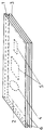
- the process for producing a decorative facade protection consists of sticking on the back of a glass plate 1, using transparent adhesive 2 applied to all desired locations, a decorative support 3, by the decorative face of this support 3, to protect the aesthetics of this support 3 against bumps and scratches or other non-repairable external aggressions, without harming the aesthetics of all.
- the glass plate 1 may consist of ordinary glass not machined, i.e. neither hardened, drilled, nor shaped before gluing on the support decorative 3.
- this decorative support 3 is advantageously no longer pierced before sticking it to the back of the glass plate 1.
- the transparent adhesive 2 is preferably applied to the rear face of the glass plate 1. It is also possible to apply transparent adhesive 2 to the face front of the decorative support 3, possibly in combination with an application on the rear face of the glass plate 1.
- the bonded assembly is machined after assembly by gluing of the glass plate 1 and the decorative support 3, by drilling 4 and / or shaping other recesses 5 and / or shaping edges 6.
- a such machining allows a substantial reduction in manufacturing costs, because it is performed simultaneously on the glass plate 1 and on the decorative support 3 bonded to the rear face of this plate 1.
- this machining of the bonded assembly can be realized with an existing simple tool usually used for glass processing alone.
- the transparent adhesive 2 is advantageously an adhesive of the resin type single component solvent free, UV curing, such as that known under the trade name VITRALIT 6127.
- This glue can be deposited by screen printing, brush or roller on the back of the plate of glass 1 at all the desired locations and / or on the front face of the decorative support.
- this adhesive is advantageously compatible with the expansions of bonded materials mounted as a unit, in particular on an apparatus household appliances, in particular for cooking.
- the transparent adhesive layer 2 is deposited by screen printing, brush or roller, its positioning can be perfectly precise, the screen or screens used for this purpose being easily adjustable in position and can have cutouts perfectly adapted to needs, that is to say to the contours of the holes 4 or other cuts 5 made subsequently. It results that said layer 3 can also fulfill the function of a seal and advantageously replace the two-sided adhesive currently used. Furthermore, this fastening mode allows for precise and reliable positioning and repetitive.
- the decorative support 3 can be made of any material compatible with a transparent adhesive of the one-component resin type without ultraviolet polymerizing solvent.
- This decorative support 3 will advantageously of a metal, the surface of which has been treated for the purpose of improve aesthetics or a synthetic material and preferably steel brushed stainless or not.
- the aesthetics of the bonded assembly obtained is thus equivalent to that of the decorative support 3 alone, the essential advantage resides in the causes the glass to protect said decorative support 3 against any degradation, which is particularly true for surfaces treated for the purpose of improvement aesthetics, the surface condition then being weakened, and in particular in the case of a decorative support 3 in brushed stainless steel. Indeed, the glass plate 1 then protects the brushed stainless steel from scratches and bumps to which it is very sensitive.
- this combination of glass and support made of another material stiffens the bonded assembly, which makes it more impact-resistant, so that the thickness of the glass plate 1 can be reduced, which results in a reduction cost and weight of the whole.
- the decorative support 3 can be provided with a decoration engraved, drawn or printed, in particular by screen printing. Due to the mounting of the glass plate 1 on said decorative support 3, this decoration cannot be damaged by impact or scratch.
- the glass plate 1 can also be provided with a decoration by screen printing.
- An impression by serigraphy on the two constituent parts of the bonded assembly allows obtaining optical effects thanks to a judicious positioning of the screen-printed decoration by relation to the decoration of the decorative support.
- Such an impression on both parties can allow to hide certain areas of the decorative support 3, which can then be used for mounting the composite panel on a device.
- a serigraphy on glass can allow to hide fixing brackets making part of the decorative support 3.
- This decorative support 3 can also be formed of so as to integrate the means necessary for fixing the assembly glued to a device without intermediate element, such as brackets, rails, clips, which are generally reported for this purpose.
- the element metal on the back of the glass allows, for a glass mounted on a door stove or baking oven to serve as a heat shield or radiator distribution of heat and thereby reducing the surface temperature to the outside of the cooking appliance door.
- the invention it is possible to produce a glued assembly allowing to obtain an aesthetic, rigid panel, impact resistant and little sensitive to scratches, by combining, by gluing with a transparent glue, a glass to a decorative support, the latter being glued on the rear face and no longer in front of the glass.
Landscapes
- Engineering & Computer Science (AREA)
- Chemical & Material Sciences (AREA)
- Combustion & Propulsion (AREA)
- Mechanical Engineering (AREA)
- General Engineering & Computer Science (AREA)
- Joining Of Glass To Other Materials (AREA)
- Securing Of Glass Panes Or The Like (AREA)
- Washing And Drying Of Tableware (AREA)
Abstract
Description
Claims (12)
- Procédé de réalisation d'une protection de façade décorative formant bandeau de commande ou élément de porte ou plan de cuisson, notamment pour appareil électroménager, caractérisé en ce qu'il consiste à coller en face arrière d'une plaque de verre (1), au moyen d'une colle transparente (2) appliquée à tous les endroits souhaités, un support décoratif (3), par la face décorative de ce support (3), afin de protéger l'esthétique de ce support (3) contre les chocs et les rayures ou autres agressions extérieures non réparables, sans nuire à l'esthétique de l'ensemble.
- Procédé, suivant la revendication 1, caractérisé en ce que la colle transparente (2) est appliquée sur la face arrière de la plaque de verre (1).
- Procédé, suivant la revendication 1, caractérisé en ce que la colle transparente (2) est appliquée sur la face avant du support décoratif (3), éventuellement en combinaison avec une application sur la face arrière de la plaque de verre (1).
- Procédé, suivant la revendication 1, caractérisé en ce que l'ensemble collé est usiné après assemblage par collage de la plaque de verre (1) et du support décoratif (3).
- Procédé, suivant la revendication 1, caractérisé en ce que la colle transparente (2) est du type résine mono-composant sans solvant polymérisant aux ultraviolets et est compatible avec les dilatations des matériaux collés montés sous forme d'un ensemble, en particulier sur un appareil électroménager, notamment de cuisson.
- Procédé, suivant la revendication 5, caractérisé en ce que la colle transparente (2) est du type connu sous la dénomination commerciale VITRALIT 6127.
- Procédé, suivant l'une quelconque des revendications 1 à 3 et 5, caractérisé en ce que la colle est déposée au pinceau, au rouleau ou par sérigraphie.
- Procédé, suivant l'une quelconque des revendications 1, 3 et 4, caractérisé en ce que le support décoratif (3) est constitué en tout matériau compatible avec une colle transparente du type résine mono-composant sans solvant polymérisant aux ultraviolets.
- Procédé, suivant l'une quelconque des revendications 1, 3, 4 et 7, caractérisé en ce que le support décoratif (3) est constitué en un métal traitée dans le but d'en améliorer l'esthétique ou une matière synthétique.
- Procédé, suivant l'une quelconque des revendications 1, 3, 4 et 7 à 9, caractérisé en ce que le support décoratif (3) est constitué en acier inoxydable brossé ou non.
- Procédé, suivant l'une quelconque des revendications 1, 3, 4 et 7 à 10, caractérisé en ce que le support décoratif (3) est pourvu d'un décor gravé, dessiné ou imprimé.
- Procédé, suivant l'une quelconque des revendications 1 à 3, caractérisé en ce que la plaque de verre (1) est pourvue d'un décor par sérigraphie permettant des effets optiques grâce au positionnement judicieux de celui-ci par rapport au décor du support décoratif (3).
Applications Claiming Priority (2)
| Application Number | Priority Date | Filing Date | Title |
|---|---|---|---|
| FR9610460 | 1996-08-22 | ||
| FR9610460A FR2752542B1 (fr) | 1996-08-22 | 1996-08-22 | Procede de realisation d'un panneau composite |
Publications (2)
| Publication Number | Publication Date |
|---|---|
| EP0826489A1 true EP0826489A1 (fr) | 1998-03-04 |
| EP0826489B1 EP0826489B1 (fr) | 1998-11-04 |
Family
ID=9495217
Family Applications (1)
| Application Number | Title | Priority Date | Filing Date |
|---|---|---|---|
| EP19970440069 Expired - Lifetime EP0826489B1 (fr) | 1996-08-22 | 1997-08-21 | Procédé de réalisation d'un panneau décoratif d'appareil électro-ménager |
Country Status (4)
| Country | Link |
|---|---|
| EP (1) | EP0826489B1 (fr) |
| DE (1) | DE69700048T2 (fr) |
| ES (1) | ES2126413T3 (fr) |
| FR (1) | FR2752542B1 (fr) |
Cited By (10)
| Publication number | Priority date | Publication date | Assignee | Title |
|---|---|---|---|---|
| EP0916304A1 (fr) * | 1997-11-14 | 1999-05-19 | Ciapem | Procédé de realisation d'un plan de travail ou de pose d'appareils electromenagers |
| RU2187476C1 (ru) * | 2001-07-19 | 2002-08-20 | ГУ "Дирекция по эксплуатации зданий и финансово-хозяйственному обеспечению" в г. Санкт-Петербурге Российской академии художеств | Стекло для золотой фольгированной смальты и способ изготовления золотой фольгированной смальты |
| EP1283105A1 (fr) * | 2001-08-08 | 2003-02-12 | BSH Bosch und Siemens Hausgeräte GmbH | Panneau frontal pour un appareil électrique |
| EP1411408A1 (fr) * | 2002-10-19 | 2004-04-21 | Electrolux Home Products Corporation N.V. | Diaphragme d'insertion pour appareil ménager |
| WO2007118744A1 (fr) * | 2006-04-12 | 2007-10-25 | BSH Bosch und Siemens Hausgeräte GmbH | Plaque à décor permanent |
| WO2008003778A1 (fr) * | 2006-07-07 | 2008-01-10 | BSH Bosch und Siemens Hausgeräte GmbH | Appareil électrodomestique |
| US20110126578A1 (en) * | 2008-08-20 | 2011-06-02 | Lg Electronics Inc. | Refrigerator and method of fabricating the same |
| US20110241503A1 (en) * | 2004-01-12 | 2011-10-06 | Lee Simon | Decorative commercial or professional kitchen or food service area appliance unit with interchangeable form fitting cover and a facade panel |
| CN102892941A (zh) * | 2010-05-28 | 2013-01-23 | 伊莱克斯家用产品股份有限公司 | 用于装配电器尤其是家用电器的面板的方法 |
| EP3182018A1 (fr) * | 2015-12-18 | 2017-06-21 | BSH Hausgeräte GmbH | Four comprenant un panneau de commande |
Families Citing this family (8)
| Publication number | Priority date | Publication date | Assignee | Title |
|---|---|---|---|---|
| DE10129370A1 (de) * | 2001-06-20 | 2003-09-11 | Robert Laskowski | Grillvorrichtung mit besonderen Schutzschilden |
| DE102004044183A1 (de) * | 2004-09-13 | 2006-03-16 | BSH Bosch und Siemens Hausgeräte GmbH | Verblendungsteil für Haushaltsgerät, Haushaltsgerät und Verfahren zur Herstellung eines Verblendungsteils |
| DE102008040763B4 (de) | 2008-07-28 | 2022-11-10 | BSH Hausgeräte GmbH | Glasplatte für ein Hausgerät |
| DE102008040762A1 (de) | 2008-07-28 | 2010-02-04 | BSH Bosch und Siemens Hausgeräte GmbH | Glasplatte für ein Hausgerät |
| KR101114320B1 (ko) | 2008-11-05 | 2012-02-14 | 엘지전자 주식회사 | 가전기기 및 세척물 처리기기 |
| CN103702533B (zh) * | 2013-11-30 | 2018-11-06 | 宁波方太厨具有限公司 | 用于家用电器的复合面板结构 |
| US10859253B2 (en) | 2018-01-23 | 2020-12-08 | Haier Us Appliance Solutions, Inc. | Door for a dishwasher appliance |
| DE102019128867A1 (de) * | 2019-10-25 | 2021-04-29 | Irlbacher Blickpunkt Glas Gmbh | Verbundmaterial umfassend mit einer Metallschicht versehenes Glas |
Citations (7)
| Publication number | Priority date | Publication date | Assignee | Title |
|---|---|---|---|---|
| BE391464A (fr) * | ||||
| GB2153744A (en) * | 1984-02-08 | 1985-08-29 | Pearce & Cutler Glass Limited | Laminated structure and method of manufacture |
| FR2658166A1 (fr) * | 1990-02-13 | 1991-08-16 | Remy Martin Cie E | Dispositif d'inviolabilite pour capsule de bouteille. |
| US5049433A (en) * | 1990-05-17 | 1991-09-17 | The Answer Corp. | Architectural safety glass |
| FR2662398A1 (fr) * | 1990-05-22 | 1991-11-29 | Flachglas Ag | Procede de fabrication d'une vitre en verre de securite feuillete comportant un dispositif de raccordement electrique. |
| DE9310235U1 (de) * | 1993-07-09 | 1993-11-11 | Veno Fenster Systeme GmbH, 52222 Stolberg | Füllung zum Herstellen eines dekorativen Fensters oder Tür, insbesondere Haustür |
| DE9420897U1 (de) * | 1994-12-29 | 1995-04-20 | BSH Bosch und Siemens Hausgeräte GmbH, 81669 München | Tür zum Verschließen einer beheizbaren Ofenmuffel von Back- und Bratöfen |
-
1996
- 1996-08-22 FR FR9610460A patent/FR2752542B1/fr not_active Expired - Fee Related
-
1997
- 1997-08-21 ES ES97440069T patent/ES2126413T3/es not_active Expired - Lifetime
- 1997-08-21 EP EP19970440069 patent/EP0826489B1/fr not_active Expired - Lifetime
- 1997-08-21 DE DE1997600048 patent/DE69700048T2/de not_active Expired - Lifetime
Patent Citations (7)
| Publication number | Priority date | Publication date | Assignee | Title |
|---|---|---|---|---|
| BE391464A (fr) * | ||||
| GB2153744A (en) * | 1984-02-08 | 1985-08-29 | Pearce & Cutler Glass Limited | Laminated structure and method of manufacture |
| FR2658166A1 (fr) * | 1990-02-13 | 1991-08-16 | Remy Martin Cie E | Dispositif d'inviolabilite pour capsule de bouteille. |
| US5049433A (en) * | 1990-05-17 | 1991-09-17 | The Answer Corp. | Architectural safety glass |
| FR2662398A1 (fr) * | 1990-05-22 | 1991-11-29 | Flachglas Ag | Procede de fabrication d'une vitre en verre de securite feuillete comportant un dispositif de raccordement electrique. |
| DE9310235U1 (de) * | 1993-07-09 | 1993-11-11 | Veno Fenster Systeme GmbH, 52222 Stolberg | Füllung zum Herstellen eines dekorativen Fensters oder Tür, insbesondere Haustür |
| DE9420897U1 (de) * | 1994-12-29 | 1995-04-20 | BSH Bosch und Siemens Hausgeräte GmbH, 81669 München | Tür zum Verschließen einer beheizbaren Ofenmuffel von Back- und Bratöfen |
Cited By (12)
| Publication number | Priority date | Publication date | Assignee | Title |
|---|---|---|---|---|
| EP0916304A1 (fr) * | 1997-11-14 | 1999-05-19 | Ciapem | Procédé de realisation d'un plan de travail ou de pose d'appareils electromenagers |
| RU2187476C1 (ru) * | 2001-07-19 | 2002-08-20 | ГУ "Дирекция по эксплуатации зданий и финансово-хозяйственному обеспечению" в г. Санкт-Петербурге Российской академии художеств | Стекло для золотой фольгированной смальты и способ изготовления золотой фольгированной смальты |
| EP1283105A1 (fr) * | 2001-08-08 | 2003-02-12 | BSH Bosch und Siemens Hausgeräte GmbH | Panneau frontal pour un appareil électrique |
| EP1411408A1 (fr) * | 2002-10-19 | 2004-04-21 | Electrolux Home Products Corporation N.V. | Diaphragme d'insertion pour appareil ménager |
| US20110241503A1 (en) * | 2004-01-12 | 2011-10-06 | Lee Simon | Decorative commercial or professional kitchen or food service area appliance unit with interchangeable form fitting cover and a facade panel |
| WO2007118744A1 (fr) * | 2006-04-12 | 2007-10-25 | BSH Bosch und Siemens Hausgeräte GmbH | Plaque à décor permanent |
| WO2008003778A1 (fr) * | 2006-07-07 | 2008-01-10 | BSH Bosch und Siemens Hausgeräte GmbH | Appareil électrodomestique |
| US20110126578A1 (en) * | 2008-08-20 | 2011-06-02 | Lg Electronics Inc. | Refrigerator and method of fabricating the same |
| US8439461B2 (en) * | 2008-08-20 | 2013-05-14 | Lg Electronic Inc. | Refrigerator and method of fabricating the same |
| CN102892941A (zh) * | 2010-05-28 | 2013-01-23 | 伊莱克斯家用产品股份有限公司 | 用于装配电器尤其是家用电器的面板的方法 |
| CN102892941B (zh) * | 2010-05-28 | 2015-09-09 | 伊莱克斯家用产品股份有限公司 | 用于装配电器尤其是家用电器的面板的方法 |
| EP3182018A1 (fr) * | 2015-12-18 | 2017-06-21 | BSH Hausgeräte GmbH | Four comprenant un panneau de commande |
Also Published As
| Publication number | Publication date |
|---|---|
| ES2126413T3 (es) | 1999-03-16 |
| DE69700048D1 (de) | 1998-12-10 |
| DE69700048T2 (de) | 2000-05-11 |
| FR2752542A1 (fr) | 1998-02-27 |
| EP0826489B1 (fr) | 1998-11-04 |
| FR2752542B1 (fr) | 1998-11-20 |
Similar Documents
| Publication | Publication Date | Title |
|---|---|---|
| EP0826489B1 (fr) | Procédé de réalisation d'un panneau décoratif d'appareil électro-ménager | |
| EP2737247B1 (fr) | Vitrage multiple lumineux de meuble | |
| WO2002070623A3 (fr) | Articles de protection | |
| US5098760A (en) | Beveled glass panel and method of making | |
| FR2967236A1 (fr) | Article vitroceramique lumineux | |
| EP0868960B1 (fr) | Procédé de réalisation de bandeaux de commande, notamment pour appareils électroménagers | |
| MXPA03001140A (es) | Elemento plano que tiene una superficie obscura y que muestra absorcion solar reducida. | |
| EP1845069B1 (fr) | Procédé de réalisation d'un élément de décor sur les deux faces d'un panneau de verre ou de vitrocéramique et panneau obtenu par ce procédé | |
| EP1493306A1 (fr) | Plaques vitroceramiques, leur procede de fabrication et tables de cuisson equipees de ces plaques | |
| US4473424A (en) | Decorative mirrored article | |
| EP1518444B1 (fr) | Plaque vitroceramique et son procede de fabrication | |
| WO2004007388A8 (fr) | Marquage de substrats traites thermiquement | |
| EP1167073A1 (fr) | Procédé de réalisation d'une imitation de facade métallique d'appareil électroménager. | |
| EP0802375B1 (fr) | Dispositif de fixation par collage d'un élément verrier | |
| DE50212050D1 (de) | Baubeschlag-Unterkonstruktion | |
| HK1052035A1 (zh) | 用於将玻璃元件固定到基体上的装置 | |
| FR2929939A1 (fr) | Vitre en verre feuillete | |
| FR2790067A1 (fr) | Plaque en vitroceramique presentant sur sa face inferieure une structure bosselee, et procede de fabrication d'une telle plaque | |
| FR2700500A1 (fr) | Procédé de gravure sur substrat stratifié et support gravé ainsi obtenu. | |
| CN222397311U (zh) | 一种水晶烫钻 | |
| CN2325384Y (zh) | 一种艺术镭射玻璃板 | |
| FR2780255A1 (fr) | Procede de fabrication d'un materiau notamment pour l'ameublement ledit materiau et le mobilier realise dans ledit materiau | |
| BE1013813A3 (fr) | Emaillages pour vitrage. | |
| US20080121331A1 (en) | Method of Glass-to-Glass Adhesion Using Locators | |
| FR2772884A1 (fr) | Panneau d'habillage adapte pour intercepter un flux de lumiere |
Legal Events
| Date | Code | Title | Description |
|---|---|---|---|
| PUAI | Public reference made under article 153(3) epc to a published international application that has entered the european phase |
Free format text: ORIGINAL CODE: 0009012 |
|
| AK | Designated contracting states |
Kind code of ref document: A1 Designated state(s): AT BE CH DE DK ES FI FR GB GR IE IT LI LU MC NL PT SE |
|
| AX | Request for extension of the european patent |
Free format text: AL;LT;LV;RO;SI |
|
| 17P | Request for examination filed |
Effective date: 19980205 |
|
| 17Q | First examination report despatched |
Effective date: 19980326 |
|
| GRAG | Despatch of communication of intention to grant |
Free format text: ORIGINAL CODE: EPIDOS AGRA |
|
| GRAG | Despatch of communication of intention to grant |
Free format text: ORIGINAL CODE: EPIDOS AGRA |
|
| GRAH | Despatch of communication of intention to grant a patent |
Free format text: ORIGINAL CODE: EPIDOS IGRA |
|
| GRAH | Despatch of communication of intention to grant a patent |
Free format text: ORIGINAL CODE: EPIDOS IGRA |
|
| GRAA | (expected) grant |
Free format text: ORIGINAL CODE: 0009210 |
|
| AK | Designated contracting states |
Kind code of ref document: B1 Designated state(s): CH DE ES FR GB IT LI NL SE |
|
| REG | Reference to a national code |
Ref country code: CH Ref legal event code: EP |
|
| AKX | Designation fees paid |
Free format text: CH DE ES FR GB IT LI NL SE |
|
| RBV | Designated contracting states (corrected) |
Designated state(s): CH DE ES FR GB IT LI NL SE |
|
| REG | Reference to a national code |
Ref country code: CH Ref legal event code: NV Representative=s name: HANS RUDOLF GACHNANG PATENTANWALT |
|
| REF | Corresponds to: |
Ref document number: 69700048 Country of ref document: DE Date of ref document: 19981210 |
|
| GBT | Gb: translation of ep patent filed (gb section 77(6)(a)/1977) |
Effective date: 19981204 |
|
| REG | Reference to a national code |
Ref country code: IE Ref legal event code: FG4D Free format text: FRENCH |
|
| ITF | It: translation for a ep patent filed | ||
| REG | Reference to a national code |
Ref country code: ES Ref legal event code: FG2A Ref document number: 2126413 Country of ref document: ES Kind code of ref document: T3 |
|
| PLBE | No opposition filed within time limit |
Free format text: ORIGINAL CODE: 0009261 |
|
| STAA | Information on the status of an ep patent application or granted ep patent |
Free format text: STATUS: NO OPPOSITION FILED WITHIN TIME LIMIT |
|
| REG | Reference to a national code |
Ref country code: IE Ref legal event code: FD4D |
|
| 26N | No opposition filed | ||
| REG | Reference to a national code |
Ref country code: GB Ref legal event code: IF02 |
|
| PGFP | Annual fee paid to national office [announced via postgrant information from national office to epo] |
Ref country code: CH Payment date: 20110819 Year of fee payment: 15 |
|
| PGFP | Annual fee paid to national office [announced via postgrant information from national office to epo] |
Ref country code: GB Payment date: 20120629 Year of fee payment: 16 |
|
| PGFP | Annual fee paid to national office [announced via postgrant information from national office to epo] |
Ref country code: SE Payment date: 20120829 Year of fee payment: 16 |
|
| PGFP | Annual fee paid to national office [announced via postgrant information from national office to epo] |
Ref country code: NL Payment date: 20120814 Year of fee payment: 16 |
|
| REG | Reference to a national code |
Ref country code: CH Ref legal event code: NV Representative=s name: GACHNANG AG PATENTANWAELTE, CH |
|
| REG | Reference to a national code |
Ref country code: NL Ref legal event code: V1 Effective date: 20140301 |
|
| REG | Reference to a national code |
Ref country code: CH Ref legal event code: PL |
|
| REG | Reference to a national code |
Ref country code: SE Ref legal event code: EUG |
|
| GBPC | Gb: european patent ceased through non-payment of renewal fee |
Effective date: 20130821 |
|
| PG25 | Lapsed in a contracting state [announced via postgrant information from national office to epo] |
Ref country code: CH Free format text: LAPSE BECAUSE OF NON-PAYMENT OF DUE FEES Effective date: 20130831 Ref country code: NL Free format text: LAPSE BECAUSE OF NON-PAYMENT OF DUE FEES Effective date: 20140301 Ref country code: LI Free format text: LAPSE BECAUSE OF NON-PAYMENT OF DUE FEES Effective date: 20130831 Ref country code: SE Free format text: LAPSE BECAUSE OF NON-PAYMENT OF DUE FEES Effective date: 20130822 |
|
| PG25 | Lapsed in a contracting state [announced via postgrant information from national office to epo] |
Ref country code: GB Free format text: LAPSE BECAUSE OF NON-PAYMENT OF DUE FEES Effective date: 20130821 |
|
| REG | Reference to a national code |
Ref country code: FR Ref legal event code: PLFP Year of fee payment: 20 |
|
| PGFP | Annual fee paid to national office [announced via postgrant information from national office to epo] |
Ref country code: DE Payment date: 20160830 Year of fee payment: 20 Ref country code: IT Payment date: 20160829 Year of fee payment: 20 |
|
| PGFP | Annual fee paid to national office [announced via postgrant information from national office to epo] |
Ref country code: FR Payment date: 20160823 Year of fee payment: 20 |
|
| PGFP | Annual fee paid to national office [announced via postgrant information from national office to epo] |
Ref country code: ES Payment date: 20160830 Year of fee payment: 20 |
|
| REG | Reference to a national code |
Ref country code: DE Ref legal event code: R071 Ref document number: 69700048 Country of ref document: DE |
|
| REG | Reference to a national code |
Ref country code: ES Ref legal event code: FD2A Effective date: 20180508 |
|
| PG25 | Lapsed in a contracting state [announced via postgrant information from national office to epo] |
Ref country code: ES Free format text: LAPSE BECAUSE OF EXPIRATION OF PROTECTION Effective date: 20170822 |