EP0823768B1 - Structure pour l'alimentation d'un moteur électrique - Google Patents
Structure pour l'alimentation d'un moteur électrique Download PDFInfo
- Publication number
- EP0823768B1 EP0823768B1 EP97401831A EP97401831A EP0823768B1 EP 0823768 B1 EP0823768 B1 EP 0823768B1 EP 97401831 A EP97401831 A EP 97401831A EP 97401831 A EP97401831 A EP 97401831A EP 0823768 B1 EP0823768 B1 EP 0823768B1
- Authority
- EP
- European Patent Office
- Prior art keywords
- brush holder
- feeding
- yoke
- retainer
- coupler case
- Prior art date
- Legal status (The legal status is an assumption and is not a legal conclusion. Google has not performed a legal analysis and makes no representation as to the accuracy of the status listed.)
- Expired - Lifetime
Links
Images


Classifications
-
- H—ELECTRICITY
- H02—GENERATION; CONVERSION OR DISTRIBUTION OF ELECTRIC POWER
- H02K—DYNAMO-ELECTRIC MACHINES
- H02K5/00—Casings; Enclosures; Supports
- H02K5/04—Casings or enclosures characterised by the shape, form or construction thereof
- H02K5/22—Auxiliary parts of casings not covered by groups H02K5/06-H02K5/20, e.g. shaped to form connection boxes or terminal boxes
- H02K5/225—Terminal boxes or connection arrangements
-
- H—ELECTRICITY
- H02—GENERATION; CONVERSION OR DISTRIBUTION OF ELECTRIC POWER
- H02K—DYNAMO-ELECTRIC MACHINES
- H02K5/00—Casings; Enclosures; Supports
- H02K5/04—Casings or enclosures characterised by the shape, form or construction thereof
- H02K5/14—Means for supporting or protecting brushes or brush holders
- H02K5/143—Means for supporting or protecting brushes or brush holders for cooperation with commutators
- H02K5/145—Fixedly supported brushes or brush holders, e.g. leaf or leaf-mounted brushes
-
- H—ELECTRICITY
- H02—GENERATION; CONVERSION OR DISTRIBUTION OF ELECTRIC POWER
- H02K—DYNAMO-ELECTRIC MACHINES
- H02K15/00—Methods or apparatus specially adapted for manufacturing, assembling, maintaining or repairing of dynamo-electric machines
- H02K15/0056—Manufacturing winding connections
-
- H—ELECTRICITY
- H02—GENERATION; CONVERSION OR DISTRIBUTION OF ELECTRIC POWER
- H02K—DYNAMO-ELECTRIC MACHINES
- H02K5/00—Casings; Enclosures; Supports
- H02K5/04—Casings or enclosures characterised by the shape, form or construction thereof
- H02K5/10—Casings or enclosures characterised by the shape, form or construction thereof with arrangements for protection from ingress, e.g. water or fingers
Landscapes
- Engineering & Computer Science (AREA)
- Power Engineering (AREA)
- Motor Or Generator Frames (AREA)
- Motor Or Generator Current Collectors (AREA)
Claims (5)
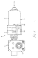
- Structure pour l'alimentation d'un moteur électrique, comprenant un porte-balais (4) dans lequel sont disposés des balais (5) et un boítier de coupleur d'alimentation (15) dans lequel des bornes d'alimentation (14) sont ajustées afin d'alimenter en énergie les balais (5) par connexion d'un coupleur externe, ledit porte-balais étant fixé à une carcasse (3) et présentant une face latérale (4a) en butée contre une face d'extrémité ouverte (3a) de ladite carcasse (3), et ledit boítier de coupleur d'alimentation (15) étant d'une seule pièce avec ledit porte-balais (4) et présentant une ouverture en regard de ladite face d'extrémité ouverte de ladite carcasse (3), les bornes d'alimentation (14), et un organe de retenue (16) pour positionner et supporter lesdits bornes d'alimentation (14) dans ledit boítier d'alimentation (15), étant ajustés dans une ouverture du boítier d'alimentation (15), ledit organe de retenue (16) ayant une partie de prévention de dégagement (16b) qui est maintenue entre ledit porte-balais (4) et ladite carcasse (3) pour empêcher ledit organe de retenue (16) de se dégager de l'ouverture du dit boítier de coupleur d'alimentation (15), caractérisée en ce que :
ledit boítier de coupleur d'alimentation (15) a la forme d'un cylindre pourvu d'un fond, avec une fente formée longitudinalement dans sa paroi opposée à ladite carcasse (3), ladite partie de prévention de dégagement étant disposée dans la fente pour former une paroi intérieure sensiblement continue avec la paroi du boítier de coupleur d'alimentation (15). - Structure pour l'alimentation d'un moteur électrique selon la revendication 1, caractérisée en ce qu'une gorge concave (4b) est ménagée sur un côté du dit porte-balais (4) qui vient en butée contre ladite carcasse (3) de sorte que ladite gorge concave (4b) se prolonge à partir dudit boítier de coupleur d'alimentation (15) et ladite partie de prévention de dégagement (16b) engage ladite gorge concave (4b) pour empêcher ledit organe de retenue (16) de se dégager de ladite ouverture du dit boítier de coupleur d'alimentation (15).
- Structure pour l'alimentation d'un moteur électrique selon la revendication 1 ou 2, caractérisée en ce que lesdites bornes d'alimentation (14) sont d'une seule pièce avec des appuis en plomb (12) supportant lesdits balais (5) et les extrémités des dits appuis en plomb (12) sur lesquelles sont portées lesdits balais (5) sont fixées au dit porte-balais (4).
- Structure d'alimentation pour moteur électrique selon la revendication 3, caractérisée en ce que des griffes de verrouillage (12b) font saillie depuis les appuis en plomb (12) et sont pressées et fixées dans ledit porte-balais (4) afin de fixer lesdits appuis en plomb (12) au dit porte-balais (4).
- Structure d'alimentation pour moteur électrique selon la revendication 1, 2, 3 ou 4, caractérisée en ce qu'une partie d'étanchéité annulaire (16e) est formée d'une seule pièce avec ledit organe de retenue (16) pour assurer l'étanchéité entre ladite face d'extrémité ouverte (3a) de ladite carcasse (3) et ladite face latérale (4a) du porte-balais (4).
Applications Claiming Priority (3)
| Application Number | Priority Date | Filing Date | Title |
|---|---|---|---|
| JP221721/96 | 1996-08-05 | ||
| JP22172196A JP3274072B2 (ja) | 1996-08-05 | 1996-08-05 | 電動モータにおける給電部構造 |
| JP22172196 | 1996-08-05 |
Publications (2)
| Publication Number | Publication Date |
|---|---|
| EP0823768A1 EP0823768A1 (fr) | 1998-02-11 |
| EP0823768B1 true EP0823768B1 (fr) | 2001-10-24 |
Family
ID=16771226
Family Applications (1)
| Application Number | Title | Priority Date | Filing Date |
|---|---|---|---|
| EP97401831A Expired - Lifetime EP0823768B1 (fr) | 1996-08-05 | 1997-07-31 | Structure pour l'alimentation d'un moteur électrique |
Country Status (5)
| Country | Link |
|---|---|
| US (1) | US5886448A (fr) |
| EP (1) | EP0823768B1 (fr) |
| JP (1) | JP3274072B2 (fr) |
| CA (1) | CA2211917C (fr) |
| DE (1) | DE69707604T2 (fr) |
Cited By (2)
| Publication number | Priority date | Publication date | Assignee | Title |
|---|---|---|---|---|
| DE10342222A1 (de) * | 2003-09-11 | 2005-05-04 | K Tec Kunststoffverarbeitung G | Topf- oder becherförmiger Träger |
| DE10342221B4 (de) * | 2003-09-11 | 2008-05-08 | K-Tec Kunststoffverarbeitung Gmbh | Anordnung zur elektrischen Versorgung eines Motors |
Families Citing this family (15)
| Publication number | Priority date | Publication date | Assignee | Title |
|---|---|---|---|---|
| DE19642132A1 (de) * | 1996-10-12 | 1998-04-16 | Bosch Gmbh Robert | Elektromotor |
| DE10003901B4 (de) * | 2000-01-29 | 2004-02-05 | Schunk Metall Und Kunststoff Gmbh | Tragplatte für zumindest eine Kohlebürste |
| US6548934B1 (en) * | 2000-07-31 | 2003-04-15 | Valeo Electrical Systems, Inc. | Brush holder lead frame with integral electrical terminals |
| DE10148705A1 (de) * | 2001-10-02 | 2003-04-10 | Valeo Auto Electric Gmbh | Bürstenhaltesystem und Antriebseinrichtung |
| JP4490030B2 (ja) * | 2002-07-18 | 2010-06-23 | 株式会社ミツバ | 電動モータ |
| US6756619B2 (en) * | 2002-08-26 | 2004-06-29 | Micron Technology, Inc. | Semiconductor constructions |
| DE10342219A1 (de) | 2003-09-11 | 2005-04-21 | K Tec Kunststoffverarbeitung G | Topf- oder becherförmiger Träger |
| WO2005077017A2 (fr) * | 2004-02-06 | 2005-08-25 | Motor Products Corporation | Appareil et procede de carte a balai ameliores |
| US6949861B1 (en) * | 2004-04-13 | 2005-09-27 | Su-Chen Liao | Carbon brush holder |
| JP5118548B2 (ja) * | 2007-05-14 | 2013-01-16 | アスモ株式会社 | モータ |
| JP5682301B2 (ja) * | 2010-12-24 | 2015-03-11 | アイシン精機株式会社 | 回転電機の製造方法 |
| FR2976411B1 (fr) * | 2011-06-08 | 2016-05-06 | Valeo Systemes Dessuyage | Assemblage support charbon |
| FR2976538B1 (fr) | 2011-06-17 | 2013-07-26 | Valeo Systemes Dessuyage | Support de connecteurs et dispositif de distribution de liquide lave-glace pour balais d'essuie-glace de vehicule automobile |
| JP5792530B2 (ja) * | 2011-06-30 | 2015-10-14 | アスモ株式会社 | モータ |
| JP5959499B2 (ja) | 2013-12-27 | 2016-08-02 | マブチモーター株式会社 | モータ |
Family Cites Families (15)
| Publication number | Priority date | Publication date | Assignee | Title |
|---|---|---|---|---|
| US4041339A (en) * | 1975-11-10 | 1977-08-09 | General Motors Corporation | Dynamoelectric machine with brush holding structure |
| FR2530885A1 (fr) * | 1982-07-22 | 1984-01-27 | Marchal Equip Auto | Sous-ensemble d'alimentation pour moteur electrique, et moteur comprenant un tel sous-ensemble |
| FR2571553B1 (fr) * | 1984-10-09 | 1987-10-23 | Marchal Equip Auto | Porte-balai pour machine electrique, et machine electrique equipee d'un tel porte-balai |
| DE8527874U1 (de) * | 1985-09-30 | 1986-08-07 | Siemens AG, 1000 Berlin und 8000 München | Kommutatormotor in geschlossener Bauart |
| DE3810961A1 (de) * | 1988-03-31 | 1989-10-19 | Schunk Motorensysteme | Becherfoermiger traeger bestimmt fuer einen elektromotor |
| DE3810963C2 (de) * | 1988-03-31 | 1995-11-23 | Schunk Motorensysteme | Gitter aus elektrisch leitendem Blechmaterial sowie Verfahren zur Herstellung eines Gitters |
| JPH0649084Y2 (ja) * | 1989-03-14 | 1994-12-12 | 自動車電機工業株式会社 | 小型モータの電源接続構造 |
| EP0472746B1 (fr) * | 1990-08-17 | 1994-05-04 | Siemens Aktiengesellschaft | Moteur électrique, en particulier moteur à collecteur fermé imperméable à l'humidité, pour l'entraînement d'une pompe hydraulique fixée par bride axiale |
| US5291088A (en) * | 1989-08-25 | 1994-03-01 | Siemens Aktiengesellschaft | Electric motor with watertight construction |
| US5231321A (en) * | 1989-08-28 | 1993-07-27 | Asmo Co., Ltd. | Noise preventing arrangement of a motor |
| JPH0649100Y2 (ja) * | 1989-12-04 | 1994-12-12 | 株式会社三ツ葉電機製作所 | 直流機の配線装置 |
| US5444315A (en) * | 1992-12-18 | 1995-08-22 | Siemens Aktiengesellschaft | Bushing isolator for lead-through of electrical lines providing moisture sealing between two housings |
| EP0618659B2 (fr) * | 1993-03-31 | 2001-07-04 | Siemens Aktiengesellschaft | Unité d'entraínement à moteur-réducteur, en particulier pour lève-glace de véhicule à moteur |
| US5440186A (en) * | 1993-09-13 | 1995-08-08 | United Technologies Automotive, Inc. | Motor with isolated brush card assembly |
| DE19517667A1 (de) * | 1995-05-13 | 1996-11-14 | Vdo Schindling | Gleichstrommaschine |
-
1996
- 1996-08-05 JP JP22172196A patent/JP3274072B2/ja not_active Expired - Lifetime
-
1997
- 1997-07-29 CA CA002211917A patent/CA2211917C/fr not_active Expired - Fee Related
- 1997-07-31 DE DE69707604T patent/DE69707604T2/de not_active Expired - Fee Related
- 1997-07-31 EP EP97401831A patent/EP0823768B1/fr not_active Expired - Lifetime
- 1997-08-04 US US08/905,742 patent/US5886448A/en not_active Expired - Fee Related
Cited By (2)
| Publication number | Priority date | Publication date | Assignee | Title |
|---|---|---|---|---|
| DE10342222A1 (de) * | 2003-09-11 | 2005-05-04 | K Tec Kunststoffverarbeitung G | Topf- oder becherförmiger Träger |
| DE10342221B4 (de) * | 2003-09-11 | 2008-05-08 | K-Tec Kunststoffverarbeitung Gmbh | Anordnung zur elektrischen Versorgung eines Motors |
Also Published As
| Publication number | Publication date |
|---|---|
| JPH1051993A (ja) | 1998-02-20 |
| DE69707604T2 (de) | 2002-09-05 |
| DE69707604D1 (de) | 2001-11-29 |
| US5886448A (en) | 1999-03-23 |
| CA2211917A1 (fr) | 1998-02-05 |
| JP3274072B2 (ja) | 2002-04-15 |
| CA2211917C (fr) | 2003-04-22 |
| EP0823768A1 (fr) | 1998-02-11 |
Similar Documents
| Publication | Publication Date | Title |
|---|---|---|
| EP0823768B1 (fr) | Structure pour l'alimentation d'un moteur électrique | |
| US8342880B2 (en) | Electrical connector with elastically held terminals | |
| JP4650691B2 (ja) | 電気接続構造 | |
| US6955567B2 (en) | Junction terminal and connector having the same | |
| US7210962B2 (en) | Waterproof connector | |
| US6814581B2 (en) | Connector for towing vehicle and method of manufacturing same | |
| US7922526B2 (en) | Electrical equipment | |
| US5238420A (en) | Brushless electric signal transmission apparatus | |
| US7150633B2 (en) | Electric apparatus | |
| JP3859972B2 (ja) | 機器のシールドケースへの電線接続構造 | |
| US6537105B2 (en) | Electrical connection box | |
| EP0928900B2 (fr) | Ensemble ventilateur electrique pour système de conditionnement d' air d' un véhicule automobile | |
| JP2005228644A (ja) | コネクタ | |
| JP4602264B2 (ja) | シールドコネクタ | |
| CN113056845A (zh) | 连接器 | |
| US20010047877A1 (en) | Shield connector | |
| US20020121019A1 (en) | Method of assembling starter lead wire | |
| JPH09161893A (ja) | コネクタの接続構造 | |
| JP2001297845A (ja) | ケーブルリール | |
| JP3869139B2 (ja) | 電気接続箱 | |
| EP0762612B1 (fr) | Boítier pour un dispositif électrique | |
| CN220358368U (zh) | 接插件连接结构、车用尾翼以及车辆 | |
| US6958558B2 (en) | Electric motor in particular for a steering system in a vehicle | |
| JPH08250219A (ja) | シールドコネクタの編組接続構造 | |
| JPH04259767A (ja) | 防水コネクタ |
Legal Events
| Date | Code | Title | Description |
|---|---|---|---|
| PUAI | Public reference made under article 153(3) epc to a published international application that has entered the european phase |
Free format text: ORIGINAL CODE: 0009012 |
|
| AK | Designated contracting states |
Kind code of ref document: A1 Designated state(s): DE FR IT |
|
| AX | Request for extension of the european patent |
Free format text: AL;LT;LV;RO;SI |
|
| 17P | Request for examination filed |
Effective date: 19980806 |
|
| AKX | Designation fees paid |
Free format text: DE FR IT |
|
| RBV | Designated contracting states (corrected) |
Designated state(s): DE FR IT |
|
| 17Q | First examination report despatched |
Effective date: 19991118 |
|
| GRAG | Despatch of communication of intention to grant |
Free format text: ORIGINAL CODE: EPIDOS AGRA |
|
| GRAG | Despatch of communication of intention to grant |
Free format text: ORIGINAL CODE: EPIDOS AGRA |
|
| GRAH | Despatch of communication of intention to grant a patent |
Free format text: ORIGINAL CODE: EPIDOS IGRA |
|
| GRAH | Despatch of communication of intention to grant a patent |
Free format text: ORIGINAL CODE: EPIDOS IGRA |
|
| RAP1 | Party data changed (applicant data changed or rights of an application transferred) |
Owner name: MITSUBA CORPORATION |
|
| GRAA | (expected) grant |
Free format text: ORIGINAL CODE: 0009210 |
|
| AK | Designated contracting states |
Kind code of ref document: B1 Designated state(s): DE FR IT |
|
| REF | Corresponds to: |
Ref document number: 69707604 Country of ref document: DE Date of ref document: 20011129 |
|
| ET | Fr: translation filed | ||
| PLBE | No opposition filed within time limit |
Free format text: ORIGINAL CODE: 0009261 |
|
| STAA | Information on the status of an ep patent application or granted ep patent |
Free format text: STATUS: NO OPPOSITION FILED WITHIN TIME LIMIT |
|
| 26N | No opposition filed | ||
| PGFP | Annual fee paid to national office [announced via postgrant information from national office to epo] |
Ref country code: DE Payment date: 20080814 Year of fee payment: 12 |
|
| PGFP | Annual fee paid to national office [announced via postgrant information from national office to epo] |
Ref country code: IT Payment date: 20080728 Year of fee payment: 12 Ref country code: FR Payment date: 20080718 Year of fee payment: 12 |
|
| REG | Reference to a national code |
Ref country code: FR Ref legal event code: ST Effective date: 20100331 |
|
| PG25 | Lapsed in a contracting state [announced via postgrant information from national office to epo] |
Ref country code: FR Free format text: LAPSE BECAUSE OF NON-PAYMENT OF DUE FEES Effective date: 20090731 |
|
| PG25 | Lapsed in a contracting state [announced via postgrant information from national office to epo] |
Ref country code: DE Free format text: LAPSE BECAUSE OF NON-PAYMENT OF DUE FEES Effective date: 20100202 |
|
| PG25 | Lapsed in a contracting state [announced via postgrant information from national office to epo] |
Ref country code: IT Free format text: LAPSE BECAUSE OF NON-PAYMENT OF DUE FEES Effective date: 20090731 |