EP0823487B1 - Verfahren und vorrichtung zur schmelzreduzierung - Google Patents
Verfahren und vorrichtung zur schmelzreduzierung Download PDFInfo
- Publication number
- EP0823487B1 EP0823487B1 EP97901259A EP97901259A EP0823487B1 EP 0823487 B1 EP0823487 B1 EP 0823487B1 EP 97901259 A EP97901259 A EP 97901259A EP 97901259 A EP97901259 A EP 97901259A EP 0823487 B1 EP0823487 B1 EP 0823487B1
- Authority
- EP
- European Patent Office
- Prior art keywords
- furnaces
- combustible gases
- heat
- melt
- furnace
- Prior art date
- Legal status (The legal status is an assumption and is not a legal conclusion. Google has not performed a legal analysis and makes no representation as to the accuracy of the status listed.)
- Expired - Lifetime
Links
Images


Classifications
-
- C—CHEMISTRY; METALLURGY
- C21—METALLURGY OF IRON
- C21B—MANUFACTURE OF IRON OR STEEL
- C21B11/00—Making pig-iron other than in blast furnaces
-
- C—CHEMISTRY; METALLURGY
- C21—METALLURGY OF IRON
- C21B—MANUFACTURE OF IRON OR STEEL
- C21B13/00—Making spongy iron or liquid steel, by direct processes
- C21B13/0006—Making spongy iron or liquid steel, by direct processes obtaining iron or steel in a molten state
-
- F—MECHANICAL ENGINEERING; LIGHTING; HEATING; WEAPONS; BLASTING
- F27—FURNACES; KILNS; OVENS; RETORTS
- F27B—FURNACES, KILNS, OVENS OR RETORTS IN GENERAL; OPEN SINTERING OR LIKE APPARATUS
- F27B19/00—Combinations of different kinds of furnaces that are not all covered by any single one of main groups F27B1/00 - F27B17/00
- F27B19/02—Combinations of different kinds of furnaces that are not all covered by any single one of main groups F27B1/00 - F27B17/00 combined in one structure
-
- F—MECHANICAL ENGINEERING; LIGHTING; HEATING; WEAPONS; BLASTING
- F27—FURNACES; KILNS; OVENS; RETORTS
- F27B—FURNACES, KILNS, OVENS OR RETORTS IN GENERAL; OPEN SINTERING OR LIKE APPARATUS
- F27B3/00—Hearth-type furnaces, e.g. of reverberatory type; Electric arc furnaces ; Tank furnaces
- F27B3/10—Details, accessories or equipment, e.g. dust-collectors, specially adapted for hearth-type furnaces
- F27B3/22—Arrangements of air or gas supply devices
- F27B3/225—Oxygen blowing
-
- F—MECHANICAL ENGINEERING; LIGHTING; HEATING; WEAPONS; BLASTING
- F27—FURNACES; KILNS; OVENS; RETORTS
- F27D—DETAILS OR ACCESSORIES OF FURNACES, KILNS, OVENS OR RETORTS, IN SO FAR AS THEY ARE OF KINDS OCCURRING IN MORE THAN ONE KIND OF FURNACE
- F27D17/00—Arrangements for using waste heat; Arrangements for using, or disposing of, waste gases
- F27D17/10—Arrangements for using waste heat
-
- C—CHEMISTRY; METALLURGY
- C21—METALLURGY OF IRON
- C21B—MANUFACTURE OF IRON OR STEEL
- C21B2100/00—Handling of exhaust gases produced during the manufacture of iron or steel
- C21B2100/40—Gas purification of exhaust gases to be recirculated or used in other metallurgical processes
- C21B2100/44—Removing particles, e.g. by scrubbing, dedusting
-
- C—CHEMISTRY; METALLURGY
- C21—METALLURGY OF IRON
- C21B—MANUFACTURE OF IRON OR STEEL
- C21B2100/00—Handling of exhaust gases produced during the manufacture of iron or steel
- C21B2100/60—Process control or energy utilisation in the manufacture of iron or steel
- C21B2100/62—Energy conversion other than by heat exchange, e.g. by use of exhaust gas in energy production
-
- C—CHEMISTRY; METALLURGY
- C21—METALLURGY OF IRON
- C21B—MANUFACTURE OF IRON OR STEEL
- C21B2100/00—Handling of exhaust gases produced during the manufacture of iron or steel
- C21B2100/60—Process control or energy utilisation in the manufacture of iron or steel
- C21B2100/66—Heat exchange
-
- F—MECHANICAL ENGINEERING; LIGHTING; HEATING; WEAPONS; BLASTING
- F27—FURNACES; KILNS; OVENS; RETORTS
- F27B—FURNACES, KILNS, OVENS OR RETORTS IN GENERAL; OPEN SINTERING OR LIKE APPARATUS
- F27B3/00—Hearth-type furnaces, e.g. of reverberatory type; Electric arc furnaces ; Tank furnaces
- F27B3/04—Hearth-type furnaces, e.g. of reverberatory type; Electric arc furnaces ; Tank furnaces of multiple-hearth type; of multiple-chamber type; Combinations of hearth-type furnaces
- F27B3/045—Multiple chambers, e.g. one of which is used for charging
-
- F—MECHANICAL ENGINEERING; LIGHTING; HEATING; WEAPONS; BLASTING
- F27—FURNACES; KILNS; OVENS; RETORTS
- F27D—DETAILS OR ACCESSORIES OF FURNACES, KILNS, OVENS OR RETORTS, IN SO FAR AS THEY ARE OF KINDS OCCURRING IN MORE THAN ONE KIND OF FURNACE
- F27D17/00—Arrangements for using waste heat; Arrangements for using, or disposing of, waste gases
- F27D17/10—Arrangements for using waste heat
- F27D17/15—Arrangements for using waste heat using boilers
-
- F—MECHANICAL ENGINEERING; LIGHTING; HEATING; WEAPONS; BLASTING
- F27—FURNACES; KILNS; OVENS; RETORTS
- F27D—DETAILS OR ACCESSORIES OF FURNACES, KILNS, OVENS OR RETORTS, IN SO FAR AS THEY ARE OF KINDS OCCURRING IN MORE THAN ONE KIND OF FURNACE
- F27D17/00—Arrangements for using waste heat; Arrangements for using, or disposing of, waste gases
- F27D17/20—Arrangements for treatment or cleaning of waste gases
-
- Y—GENERAL TAGGING OF NEW TECHNOLOGICAL DEVELOPMENTS; GENERAL TAGGING OF CROSS-SECTIONAL TECHNOLOGIES SPANNING OVER SEVERAL SECTIONS OF THE IPC; TECHNICAL SUBJECTS COVERED BY FORMER USPC CROSS-REFERENCE ART COLLECTIONS [XRACs] AND DIGESTS
- Y02—TECHNOLOGIES OR APPLICATIONS FOR MITIGATION OR ADAPTATION AGAINST CLIMATE CHANGE
- Y02P—CLIMATE CHANGE MITIGATION TECHNOLOGIES IN THE PRODUCTION OR PROCESSING OF GOODS
- Y02P10/00—Technologies related to metal processing
- Y02P10/10—Reduction of greenhouse gas [GHG] emissions
- Y02P10/134—Reduction of greenhouse gas [GHG] emissions by avoiding CO2, e.g. using hydrogen
Definitions
- the present invention relates to a melt-reducing facility for directly producing molten iron or molten pig iron by throwing iron bearing material, carbon material and flux into a melt-reducing furnace and blowing pure oxygen and/or an oxygen-rich gas thereinto, and to a method of operation thereof.
- the melt-reduction is a method of directly producing molten iron or molten pig iron by throwing iron bearing material, carbon material and flux into a furnace body, blowing pure oxygen and/or an oxygen-rich gas thereinto, and reducing iron oxides of the iron bearing material in the slag. According to this method, combustible gases at temperatures as high as about 1600 to 1800°C are produced from the melt-reducing furnace.
- the method of melt-reduction of this kind can be divided into a two-stage method according to which pre-reduced iron bearing material, carbon material and flux are thrown into the furnace body, and the iron ore is pre-reduced with a CO gas and an H 2 gas contained in the combustible gases generated from the furnace body, and a single-stage method according to which unreduced iron bearing material, carbon material and flux are thrown into the furnace body, iron oxides in the iron bearing material are reduced in the slag, a CO gas and an H 2 gas in the combustible gases generated from the furnace body are completely burned in a waste heat boiler, and the sensible heat and the latent heat of the combustible gases are recovered by vaporization to generate electricity (see, for example, Japanese Unexamined Patent Publications (Kokai) No. 1-502276, No. 63-65011, No. 63-65007, etc.).
- the two-stage method has an advantage of better energy efficiency than the single-stage method, but requires a pre-reducing furnace such as of a packed bed type or a fluidized bed type, causing the facility to become complex, requiring an increased investment for the facility, and imposing limitation on the shape of iron bearing material due to uniform reaction in the pre-reducing furnace (e.g., the packed bed system permits the use of massive iron bearing material only, and the fluidized bed system permits the use of powdery iron bearing material only).
- a simple single-stage method has drawn attention.
- the energy efficiency is improved, i.e., the unit requirement of carbon material is decreased by increasing the rate of combustion of CO gas and H 2 gas generated in the slag (hereinafter referred to as secondary combustion rate in the furnace, which is defined to be (CO 2 % + H 2 O % )/(CO 2 % + CO % + H 2 O % + H 2 %)) in a space in the furnace over the slag to effectively transmit the heat of combustion to the slag, and that the amount of heat of the combustible gases, i.e., the sum of the sensible heat and the latent heat generated from the furnace body, decreases by an amount by which the unit requirement of carbon material is decreased.
- secondary combustion rate in the furnace which is defined to be (CO 2 % + H 2 O % )/(CO 2 % + CO % + H 2 O % + H 2 %)
- the operation In order to repair furnace body refractories of the melt-reducing furnace, however, the operation must be halted at regular intervals, e.g., once in three to twelve months as shown in Fig. 5. That is, no electricity is generated during the period in which the operation is halted leaving a problem from the standpoint of stably supplying electric power. For example, when the electric power is to be sold to the utility, the price must be set low or when the electric power is to be used in other facilities in the factory, operation of the other facilities in the factory is interrupted.
- US-A-3,985,544 relates to a method of combined production of electrical energy and crude iron, comprising reducing iron oxides while keeping the temperature below the melting point of the crude iron during a pre-reduction and above said melting point during a final reduction.
- the present invention was accomplished in order to solve the above-mentioned problems, and its object is to stably supply the electric power even when the operation is regularly halted in order to repair furnace body refractories in the melt-reducing furnace.
- the present invention is concerned with a melt-reducing facility for directly producing molten iron or molten pig iron by throwing iron bearing material, carbon material and flux into furnace bodies and blowing pure oxygen and/or an oxygen-rich gas thereinto, wherein a waste heat boiler and a power-generating facility are connected to a plurality of furnace bodies through ducts which can be freely opened and closed, the waste heat boiler being capable of recovering by vaporization the sensible heat and the latent heat of the combustible gases generated from the furnace bodies.
- the invention is further concerned with a method of operating the melt-reducing facility wherein when, for example, two furnaces are being operated, the secondary combustion rate in the furnaces is increased to decrease the amount of heat of the combustible gases per a furnace and when one furnace is being operated, the secondary combustion rate in the furnace is decreased to double the amount of heat of the combustible gases in one furnace, so that the amount of heat of when one furnace is operated becomes the same as the total amount of heat of the combustible gases of the two furnaces.
- a plurality of furnaces e.g., two furnaces, furnace A and furnace B, are normally operated.
- the furnace B When the operation of the furnace A is halted for repairing, the furnace B only is operated.
- the furnace A When the operation of the furnace B is halted for repairing, the furnace A only is operated.
- the electric power generated by utilizing the waste heat is continuously supplied without being interrupted.
- the secondary combustion rate in the furnace is increased to decrease the amount of heat of the combustible gases per a furnace.
- the secondary combustion rate in the furnace is decreased to double the amount of heat of the combustible gases in the furnace, so that the amount of heat becomes the same as the total amount of heat of the combustible gases of the two furnaces. It is thus made possible to constantly supply the electric power by utilizing waste heat.
- This embodiment deals with a melt-reducing facility having two furnace bodies, a waste heat boiler which recovers by vaporization the sensible heat and the latent heat of the combustible gases generated from the furnace bodies, and a power-generating facility. It need not be pointed out that the present invention can further be adapted to a melt-reducing facility having three or more furnace bodies.
- the melt-reducing furnace has two furnaces, i.e., furnace A and furnace B, the furnace bodies 1-a and 1-b having a shell lined with refractories 2-a and 2-b and water cooling panels 3-a and 3-b.
- the furnace bodies 1-a and 1-b At upper portions of the furnace bodies 1-a and 1-b are formed starting material throw ports 4-a and 4-b for throwing iron bearing material, carbon material and flux, as well as gas discharge ports 5-a and 5-b for discharging combustible gases generated from the furnace bodies.
- molten pig iron 7-a, 7-b On the bottoms of the furnace bodies 1-a and 1-b are held molten pig iron 7-a, 7-b, and on the molten pig iron is held slag 8-a and 8-b having a specific gravity smaller than that of the molten pig iron 7-a, 7-b.
- the molten pig iron 7-a and 7-b is drained through iron spouts 20-a and 20-b, and the slag 8-a and 8-b is drained through slag spouts 21-a and 21-b either continuously or intermittently.
- Iron oxides (FeO and Fe 2 O 3 ) in the iron bearing material thrown through the starting material throw ports 4-a and 4-b are reduced in the slag 8-a and 8-b with carbon component in the carbon material thrown through the starting material throw ports according to the following formulas (1) and (2), FeO + C ⁇ Fe + CO (endothermic reaction) Fe 2 O 3 + 3C ⁇ 2Fe + 3CO (endothermic reaction)
- Part of the carbon component in the carbon material thrown through the starting material throw ports 4-a and 4-b passes through the furnace bodies 1-a and 1-b, and is oxidized with oxygen blown into the slag 8-a and 8-b through lower tuyeres 9-a and 9-b arranged facing the slag 8-a and 8-b, according to the reaction of the following formula (3), C + 1/2O 2 ⁇ CO (exothermic reaction)
- the energy efficiency of the melt-reducing furnace i.e., the unit requirement of carbon material is determined by the sum of carbon components required for the reactions of the formulas (1), (2) and (3).
- the CO gas generated in the slag 8-a and 8-b as expressed by the above-mentioned formulas (1), (2) and (3) and hydrogen component in the carbon material pass through the furnace bodies 1-a and 1-b, and are oxidized with oxygen that is blown into the secondary combustion zones 11-a and 11-b through upper tuyeres 10-a and 10-b arranged facing the secondary combustion zones, according to the reactions of the following formulas (4) and (5), CO + 1/2O 2 ⁇ CO 2 (exothermic reaction) H 2 + 1/2O 2 ⁇ H 2 O (exothermic reaction)
- the reaction heat in the secondary combustion zones 11-a and 11-b represented by the formulas (4) and (5) is partly transmitted to the slags 8-a and 8-b.
- the unit requirement of carbon material decreases and the amount of heat of the combustible gases decreases.
- Fig. 1 illustrates a state where both the furnace A and the furnace B are being operated.
- the combustible gases of high temperatures generated from the furnace A and the furnace B are guided into a waste heat boiler 12 passing through gas discharge ports 5-a and 5-b disposed at upper portions of the furnace bodies 1-a and 1-b, discharge gas ducts 6-a and 6-b, discharge gas dampers 19-a and 19-b which are both being opened, and a combined discharge gas duct 16.
- the combustible gases are discharged out of the system through a dust collector 13, blower 14 and chimney 15.
- the vapor at a high pressure generated in the waste heat boiler 12 being heated by sensible heat and latent heat of the combustible gases, is guided into a turbine 17 through a vapor conduit 16 and is transformed into electric power by a generator 18.
- Fig. 2 illustrates a state where the furnace A is in operation and the furnace B is not in operation.
- the combustible gases of high temperatures generated from the furnace A are guided into the waste heat boiler 12 passing through a gas discharge port 5-a disposed at the upper portion of the furnace body 2-a, a discharge gas duct 6-a and a discharge gas damper 19-a which is opened. After the sensible heat and the latent heat are recovered by vaporization, the combustible gases are discharged out of the system through the dust collector 13, blower 14 and chimney 15.
- the vapor at a high pressure generated in the waste heat boiler 12 being heated by the sensible heat and the latent heat of the combustible gases is guided into the turbine 17 through the vapor conduit 16 and is transformed into electric power by the generator 18.
- the exhaust gas damper 19-b is closed. Therefore, even when the furnace B is not in operation, none of the operation of the furnace A or the recovery of sensible heat and latent heat of the combustible gases by vaporization is hindered.
- melt-reducing facility having two furnace bodies (furnace A and furnace B), a waste heat boiler, and a power-generating facility.
- the two furnaces of furnace A and furnace B were operated in an ordinary manner.
- the total amount of heat of the combustible gases of the two furnaces was set to be 300 Gcal/h
- the amount of power generation was set to be 120 KW that corresponds to the above amount of heat
- the iron bearing material and carbon material were thrown in amounts as shown in Table 1
- a pure oxygen gas was blown at a rate of 28,000 m 3 /h in terms of the amount of oxygen through the upper tuyere
- the combustible gases generated from the furnace bodies were burned at a high secondary combustion rate (70%) in the secondary combustion zones in the furnace.
- the total amount of heat of the combustible gases of the two furnaces was 304 Gcal/h as shown in Table 1, and the amount of electric power generated was 124 KW.
- a target value of the amount of heat of the obtained combustible gases was set to be 300 Gcal/h as in the case when the two furnaces were operated, a pure oxygen gas was blown at a rate of 24,000 m 3 in terms of the amount of oxygen through the upper tuyere, and the combustible gases generated from the furnace body were burned at a low secondary combustion rate (40%) in the secondary combustion zone in the furnace.
- the amount of heat of the obtained combustible gases was 304 Gcal/h as shown in Table 1, and the amount of electric power generated was 124 KW.
- the amount of electric power generated by operating one furnace was the same as the amount of electric power generated by operating the two furnaces. Therefore, the electric power could be stably supplied despite the operation of the furnace B being halted.
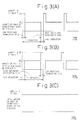
- Figs. 3(A) and 3(B) illustrate relationships between the operation time and the amount of heat of the combustible gases under the above-mentioned operation conditions.
- Fig. 3(B) the operation of the furnace B was halted for a predetermined period of time and, during this period, the combustible gases were burned at a low secondary combustion rate in the furnace A to increase the amount of heat to A 1 as shown in Fig. 3(A), which was then supplied to the waste heat boiler.
- both the furnace A and the furnace B are usually operated.
- the furnace B only is operated.
- the furnace A only is operated.
- the furnace A only is operated.
- the secondary combustion rate is increased in the furnaces to decrease the amount of heat of the combustible gases in each furnace.
- the secondary combustion rate is decreased in the furnace to double the amount of heat of the combustible gases in the furnace.
Landscapes
- Engineering & Computer Science (AREA)
- Chemical & Material Sciences (AREA)
- Mechanical Engineering (AREA)
- General Engineering & Computer Science (AREA)
- Manufacturing & Machinery (AREA)
- Materials Engineering (AREA)
- Metallurgy (AREA)
- Organic Chemistry (AREA)
- Environmental & Geological Engineering (AREA)
- Vertical, Hearth, Or Arc Furnaces (AREA)
- Manufacture Of Iron (AREA)
- Waste-Gas Treatment And Other Accessory Devices For Furnaces (AREA)
Claims (7)
- Schmelzreduziervorrichtung zum direkten Erzeugen geschmolzenen Eisens oder geschmolzenen Roheisens, aufweisend:mehrere Schmelzreduzieröfen mit einer Ausgangsmaterial-Einwurföffnung zum Einwerfen von eisenhaltigem Material, kohlenstoffhaltigem Material und Flußmittel,eine Gasauslaßleitungsstruktur, die durch Kombinieren von Gasauslaßleitungen der mehreren Öfen eine kombinierte Gasauslaßleitung bildet, wobei jede der Gasauslaßleitungen einen Gasauslaßdämpfer aufweist,einen Abwärmekessel und eine Energieerzeugungsvorrichtung, die an der kombinierten Gasauslaßleitung bereitgestellt sind, undeine Blasdüse, die in jedem der Öfen zum Einblasen von reinem Sauerstoff und/oder einem sauerstoffreichen Gas bereitgestellt ist, um die Gesamtwärmemenge von brennbaren Gasen, die von jedem der Öfen erzeugt werden, konstant zu halten.
- Schmelzreduziervorrichtung nach Anspruch 1, wobei ein Gebläse an einem Endabschnitt der kombinierten Abgasleitung über einen Staubsammler bereitgestellt ist.
- Verfahren zum Betreiben einer Schmelzreduziervorrichtung mit einer Energieerzeugungsvorrichtung und einem Abwärmekessel, die an einer kombinierten Gasauslaßleitung bereitgestellt sind, die jede Gasauslaßleitung von mehreren Schmelzreduzieröfen kombiniert, mit den Schritten:Legen der Wärmemenge der von den Schmelzreduzieröfen erzeugten und in den Abwärmekessel geleiteten brennbaren Gase auf einen vorgegebenen Wert,Öffnen der Gasauslaßdämpfer der Öfen, Einwerfen von eisenhaltigem Material, von kohlenstoffhaltigem Material und dergleichen in die Öfen, Schmelzreduzieren des eisenhaltigen Materials durch Blasen reinen Sauerstoffs und/oder eines sauerstoffreichen Gases durch eine obere und eine untere Blasdüse und sekundäres Verbrennen der brennbaren Gase in den Sekundärverbrennungszonen der Öfen,Einstellen der Sekundärverbrennungsrate durch Einstellen der Rate des Blasens reinen Sauerstoffs und/oder des sauerstoffreichen Gases durch die obere Blasdüse beim Ausführen der Sekundärverbrennung, so daß die Gesamtwärmemenge der brennbaren Gase gleich der vorgegebenen Wärmemenge der brennbaren Gase wird, undLeiten der von den Öfen erzeugten brennbaren Gase durch die kombinierte Gasauslaßleitüng in den Abwärmekessel.
- Verfahren zum Betreiben einer Schmelzreduziervorrichtung nach Anspruch 3, wobei der reine Sauerstoff und/oder das sauerstoffreiche Gas beim Ausführen der Sekundärverbrennung mit erhöhter Menge durch die obere Blasdüse geblasen wird, um die Sekundärverbrennungsrate zu erhöhen und die Wärmemenge der brennbaren Gase für jeden Ofen zu verringern, so daß die Gesamtwärmemenge der brennbaren Gase der zwei Öfen gleich der vorgegebenen Wärmemenge der brennbaren Gase wird.
- Verfahren zum Betreiben einer Schmelzreduziervorrichtung nach Anspruch 3 oder 4 mit den Schritten:Legen der Wärmemenge der von den Schmelzreduzieröfen erzeugten und in den Abwärmekessel geleiteten brennbaren Gase auf einen vorgegebenen Wert,Öffnen der Gasauslaßdämpfer der Öfen (von einem oder mehreren Öfen), die von dem Ofen verschieden sind, der unter den mehreren Öfen nicht mehr arbeitet, Einwerfen von eisenhaltigem Material, von kohlenstoffhaltigem Material und dergleichen in die Öfen, Schmelzreduzieren des eisenhaltigen Materials durch Blasen von reinem Sauerstoff und/oder eines sauerstoffreichen Gases durch die obere und die untere Blasdüse und sekundäres Verbrennen der brennbaren Gase in den Sekundärverbrennungszonen der Öfen,Einstellen der Sekundärverbrennungsrate durch Einstellen der Rate des Blasens reinen Sauerstoffs und/oder des sauerstoffreichen Gases durch die obere Blasdüse beim Ausführen der Sekundärverbrennung, so daß die Gesamtwärmemenge der brennbaren Gase gleich der vorgegebenen Wärmemenge der brennbaren Gase wird, undLeiten der von den Öfen erzeugten brennbaren Gase durch die kombinierte Gasauslaßleitung in den Abwärmekessel.
- Verfahren zum Betreiben einer Schmelzreduziervorrichtung nach Anspruch 5, wobei der reine Sauerstoff und/oder das sauerstoffreiche Gas beim Ausführen der Sekundärverbrennung mit verringerter Menge durch die obere Blasdüse geblasen wird, um die Sekundärverbrennungsrate zu verringern und die Wärmemenge der brennbaren Gase für jeden Ofen zu erhöhen, so daß die Wärmemenge der brennbaren Gase gleich der vorgegebenen Wärmemenge der brennbaren Gase wird.
- Verfahren zum Betreiben einer Schmelzreduziervorrichtung nach einem der Ansprüche 3 bis 6, wobei eine Energieerzeugungsvorrichtung und ein Abwärmekessel an einer kombinierten Abgasleitung bereitgestellt sind, die jede Gasauslaßleitung von zwei Schmelzreduzieröfen kombiniert, mit den Schritten:Legen der Wärmemenge der von den Schmelzreduzieröfen erzeugten und in den Abwärmekessel geleiteten brennbaren Gase auf einen vorgegebenen Wert,Erhöhen der Sekundärverbrennungsrate in jedem der Öfen, so daß die Wärmemenge der brennbaren Gase in jedem Ofen die Hälfte der vorgegebenen Wärmemenge der brennbaren Gase wird, wenn beide Schmelzreduzieröfen betrieben werden,Verringern der Sekundärverbrennungsrate in dem Ofen, so daß die Wärmemenge der brennbaren Gase in dem Ofen zweimal so groß wie die Wärmemenge der brennbaren Gase in einem Ofen wird, wenn die beiden Öfen betrieben werden, um die vorgegebene Wärmemenge der Verbrennungsgase zu erreichen, wenn einer der beiden Schmelzreduzieröfen betrieben wird, undLeiten der brennbaren Gase, die stets die gleiche Wärmemenge aufweisen, unabhängig vom Betriebszustand der mehreren Schmelzreduzieröfen über die kombinierte Gasauslaßleitung in den Abwärmekessel.
Applications Claiming Priority (4)
| Application Number | Priority Date | Filing Date | Title |
|---|---|---|---|
| JP8011608A JPH09202909A (ja) | 1996-01-26 | 1996-01-26 | 溶融還元設備ならびに操業方法 |
| JP1160896 | 1996-01-26 | ||
| JP11608/96 | 1996-01-26 | ||
| PCT/JP1997/000166 WO1997027336A1 (fr) | 1996-01-26 | 1997-01-24 | Dispositif de reduction d'une matiere en fusion et procede de fonctionnement associe |
Publications (3)
| Publication Number | Publication Date |
|---|---|
| EP0823487A1 EP0823487A1 (de) | 1998-02-11 |
| EP0823487A4 EP0823487A4 (de) | 1999-05-19 |
| EP0823487B1 true EP0823487B1 (de) | 2002-01-02 |
Family
ID=11782631
Family Applications (1)
| Application Number | Title | Priority Date | Filing Date |
|---|---|---|---|
| EP97901259A Expired - Lifetime EP0823487B1 (de) | 1996-01-26 | 1997-01-24 | Verfahren und vorrichtung zur schmelzreduzierung |
Country Status (7)
| Country | Link |
|---|---|
| US (1) | US6200518B1 (de) |
| EP (1) | EP0823487B1 (de) |
| JP (1) | JPH09202909A (de) |
| KR (1) | KR100250719B1 (de) |
| CN (1) | CN1069347C (de) |
| DE (1) | DE69709797T2 (de) |
| WO (1) | WO1997027336A1 (de) |
Families Citing this family (4)
| Publication number | Priority date | Publication date | Assignee | Title |
|---|---|---|---|---|
| JP2010071616A (ja) * | 2008-09-22 | 2010-04-02 | Toho Titanium Co Ltd | 金属製造用還元炉の廃熱回収方法 |
| US20140306386A1 (en) * | 2011-12-05 | 2014-10-16 | Active Land International Corporation | Sustainable process for the co-generation of pig iron and electric energy using wood as fuel |
| CA2872337A1 (en) * | 2012-05-03 | 2013-11-07 | Siemens Vai Metals Technologies Gmbh | Method for generating steam using the waste gases from plants for pig iron manufacture |
| CN104215073A (zh) * | 2013-06-04 | 2014-12-17 | 宁夏嘉翔自控技术有限公司 | 余热利用导热油锅炉系统 |
Family Cites Families (12)
| Publication number | Priority date | Publication date | Assignee | Title |
|---|---|---|---|---|
| US3060014A (en) | 1958-04-17 | 1962-10-23 | Yawata Iron & Steel Co | Multi-furnace for refining metal |
| US3320931A (en) | 1961-02-02 | 1967-05-23 | Babcock & Wilcox Co | Vapor generating apparatus |
| DD100017A5 (de) | 1971-11-01 | 1973-09-05 | ||
| AT366414B (de) | 1980-02-28 | 1982-04-13 | Voest Alpine Ag | Verfahren zur direkten herstellung von stahl aus eisenoxidhaltigen rohstoffen |
| SE451600B (sv) | 1982-12-07 | 1987-10-19 | Outokumpu Oy | Sett att konvertera metallskersten i tva parallellkopplade konvertrar |
| DE3334221A1 (de) | 1983-08-25 | 1985-03-14 | Mannesmann AG, 4000 Düsseldorf | Verfahren zur erzeugung von fluessigem, kohlenstoffhaltigem eisen aus eisenschwamm |
| JP2545804B2 (ja) | 1986-09-08 | 1996-10-23 | 日本鋼管株式会社 | 高酸化燃焼型溶融還元方法 |
| JPS6365007A (ja) | 1986-09-08 | 1988-03-23 | Nippon Kokan Kk <Nkk> | 高酸化燃焼型溶融還元方法 |
| AU604237B2 (en) | 1987-02-16 | 1990-12-13 | Moskovsky Institut Stali I Splavov | Method and furnace for making iron-carbon intermediate products for steel production |
| JPH01129914A (ja) | 1987-11-13 | 1989-05-23 | Kawasaki Heavy Ind Ltd | 溶融還元および精錬の方法 |
| JPH04311632A (ja) * | 1991-04-10 | 1992-11-04 | Mitsubishi Heavy Ind Ltd | 製鉄炉におけるエネルギ回収装置 |
| JP3625301B2 (ja) * | 1994-07-19 | 2005-03-02 | 川崎重工業株式会社 | 排熱回収発電装置 |
-
1996
- 1996-01-26 JP JP8011608A patent/JPH09202909A/ja active Pending
-
1997
- 1997-01-24 KR KR1019970706700A patent/KR100250719B1/ko not_active Expired - Fee Related
- 1997-01-24 US US08/930,416 patent/US6200518B1/en not_active Expired - Fee Related
- 1997-01-24 DE DE69709797T patent/DE69709797T2/de not_active Expired - Fee Related
- 1997-01-24 EP EP97901259A patent/EP0823487B1/de not_active Expired - Lifetime
- 1997-01-24 CN CN97190043A patent/CN1069347C/zh not_active Expired - Fee Related
- 1997-01-24 WO PCT/JP1997/000166 patent/WO1997027336A1/ja not_active Ceased
Also Published As
| Publication number | Publication date |
|---|---|
| US6200518B1 (en) | 2001-03-13 |
| DE69709797D1 (de) | 2002-02-28 |
| WO1997027336A1 (fr) | 1997-07-31 |
| CN1178559A (zh) | 1998-04-08 |
| DE69709797T2 (de) | 2002-09-19 |
| KR100250719B1 (ko) | 2000-04-01 |
| CN1069347C (zh) | 2001-08-08 |
| JPH09202909A (ja) | 1997-08-05 |
| EP0823487A4 (de) | 1999-05-19 |
| KR19980703296A (ko) | 1998-10-15 |
| EP0823487A1 (de) | 1998-02-11 |
Similar Documents
| Publication | Publication Date | Title |
|---|---|---|
| US6986800B2 (en) | Method and apparatus for improved use of primary energy sources in integrated steel plants | |
| US4940488A (en) | Method of smelting reduction of ores containing metal oxides | |
| CN114672602B (zh) | 一种焦炉煤气气基竖炉冶炼钒钛矿-电炉熔分深还原的方法 | |
| US5431710A (en) | Method for continuously producing iron, steel or semi-steel and energy | |
| ZA200300558B (en) | Method and installation for the indirect reduction of particulate oxide-containing ores. | |
| EP0823487B1 (de) | Verfahren und vorrichtung zur schmelzreduzierung | |
| KR100187693B1 (ko) | 고철 용해 방법 | |
| US4509177A (en) | Electric arc-fired blast furnace system | |
| JPH0480311A (ja) | 溶融還元炉 | |
| JP2004176170A (ja) | 溶鉄の製法 | |
| JPH04107206A (ja) | 含クロム溶鋼の製造プロセス | |
| CA1338099C (en) | Method of smelting reduction of ores containing metal oxides | |
| RU2217505C1 (ru) | Способ переработки никельсодержащего железорудного сырья | |
| JP3236737B2 (ja) | 竪型鉄スクラップ溶解炉の操業方法 | |
| JP2600732B2 (ja) | 溶融還元法及び装置 | |
| JPH03130314A (ja) | 溶融還元製鉄法 | |
| JPH11315314A (ja) | 溶融還元設備の操業方法及び溶融還元設備 | |
| CN222773768U (zh) | 铁矿石熔融还原系统 | |
| AU2005215826B2 (en) | Direct smelting plant and process | |
| JPS5980704A (ja) | 粉、粒状鉱石のたて型炉溶融還元方法 | |
| JPH01162711A (ja) | 溶融還元法 | |
| JPH0726161B2 (ja) | ステンレス鋼製造時の副生物からの有価金属回収方法 | |
| JPH01149911A (ja) | 溶融還元法 | |
| JPH06228623A (ja) | エネルギ−使用量の少ない製鋼方法 | |
| JPH0310030A (ja) | ステンレス鋼製造過程副産物の処理炉 |
Legal Events
| Date | Code | Title | Description |
|---|---|---|---|
| PUAI | Public reference made under article 153(3) epc to a published international application that has entered the european phase |
Free format text: ORIGINAL CODE: 0009012 |
|
| 17P | Request for examination filed |
Effective date: 19970923 |
|
| AK | Designated contracting states |
Kind code of ref document: A1 Designated state(s): DE FR GB |
|
| A4 | Supplementary search report drawn up and despatched |
Effective date: 19990407 |
|
| AK | Designated contracting states |
Kind code of ref document: A4 Designated state(s): DE FR GB |
|
| 17Q | First examination report despatched |
Effective date: 19991202 |
|
| GRAG | Despatch of communication of intention to grant |
Free format text: ORIGINAL CODE: EPIDOS AGRA |
|
| GRAG | Despatch of communication of intention to grant |
Free format text: ORIGINAL CODE: EPIDOS AGRA |
|
| GRAG | Despatch of communication of intention to grant |
Free format text: ORIGINAL CODE: EPIDOS AGRA |
|
| GRAG | Despatch of communication of intention to grant |
Free format text: ORIGINAL CODE: EPIDOS AGRA |
|
| GRAH | Despatch of communication of intention to grant a patent |
Free format text: ORIGINAL CODE: EPIDOS IGRA |
|
| GRAH | Despatch of communication of intention to grant a patent |
Free format text: ORIGINAL CODE: EPIDOS IGRA |
|
| GRAA | (expected) grant |
Free format text: ORIGINAL CODE: 0009210 |
|
| REG | Reference to a national code |
Ref country code: GB Ref legal event code: IF02 |
|
| AK | Designated contracting states |
Kind code of ref document: B1 Designated state(s): DE FR GB |
|
| REF | Corresponds to: |
Ref document number: 69709797 Country of ref document: DE Date of ref document: 20020228 |
|
| ET | Fr: translation filed | ||
| PLBE | No opposition filed within time limit |
Free format text: ORIGINAL CODE: 0009261 |
|
| STAA | Information on the status of an ep patent application or granted ep patent |
Free format text: STATUS: NO OPPOSITION FILED WITHIN TIME LIMIT |
|
| 26N | No opposition filed | ||
| PGFP | Annual fee paid to national office [announced via postgrant information from national office to epo] |
Ref country code: FR Payment date: 20040108 Year of fee payment: 8 |
|
| PGFP | Annual fee paid to national office [announced via postgrant information from national office to epo] |
Ref country code: GB Payment date: 20040121 Year of fee payment: 8 |
|
| PGFP | Annual fee paid to national office [announced via postgrant information from national office to epo] |
Ref country code: DE Payment date: 20040205 Year of fee payment: 8 |
|
| PG25 | Lapsed in a contracting state [announced via postgrant information from national office to epo] |
Ref country code: GB Free format text: LAPSE BECAUSE OF NON-PAYMENT OF DUE FEES Effective date: 20050124 |
|
| PG25 | Lapsed in a contracting state [announced via postgrant information from national office to epo] |
Ref country code: DE Free format text: LAPSE BECAUSE OF NON-PAYMENT OF DUE FEES Effective date: 20050802 |
|
| GBPC | Gb: european patent ceased through non-payment of renewal fee |
Effective date: 20050124 |
|
| PG25 | Lapsed in a contracting state [announced via postgrant information from national office to epo] |
Ref country code: FR Free format text: LAPSE BECAUSE OF NON-PAYMENT OF DUE FEES Effective date: 20050930 |
|
| REG | Reference to a national code |
Ref country code: FR Ref legal event code: ST |