EP0823291A2 - Schwingungsantrieb für eine Siebmaschine - Google Patents
Schwingungsantrieb für eine Siebmaschine Download PDFInfo
- Publication number
- EP0823291A2 EP0823291A2 EP97113308A EP97113308A EP0823291A2 EP 0823291 A2 EP0823291 A2 EP 0823291A2 EP 97113308 A EP97113308 A EP 97113308A EP 97113308 A EP97113308 A EP 97113308A EP 0823291 A2 EP0823291 A2 EP 0823291A2
- Authority
- EP
- European Patent Office
- Prior art keywords
- eccentric shafts
- vibration
- belts
- drive according
- vibration drive
- Prior art date
- Legal status (The legal status is an assumption and is not a legal conclusion. Google has not performed a legal analysis and makes no representation as to the accuracy of the status listed.)
- Granted
Links
Images


Classifications
-
- B—PERFORMING OPERATIONS; TRANSPORTING
- B06—GENERATING OR TRANSMITTING MECHANICAL VIBRATIONS IN GENERAL
- B06B—METHODS OR APPARATUS FOR GENERATING OR TRANSMITTING MECHANICAL VIBRATIONS OF INFRASONIC, SONIC, OR ULTRASONIC FREQUENCY, e.g. FOR PERFORMING MECHANICAL WORK IN GENERAL
- B06B1/00—Methods or apparatus for generating mechanical vibrations of infrasonic, sonic, or ultrasonic frequency
- B06B1/10—Methods or apparatus for generating mechanical vibrations of infrasonic, sonic, or ultrasonic frequency making use of mechanical energy
- B06B1/16—Methods or apparatus for generating mechanical vibrations of infrasonic, sonic, or ultrasonic frequency making use of mechanical energy operating with systems involving rotary unbalanced masses
- B06B1/161—Adjustable systems, i.e. where amplitude or direction of frequency of vibration can be varied
- B06B1/166—Where the phase-angle of masses mounted on counter-rotating shafts can be varied, e.g. variation of the vibration phase
-
- B—PERFORMING OPERATIONS; TRANSPORTING
- B07—SEPARATING SOLIDS FROM SOLIDS; SORTING
- B07B—SEPARATING SOLIDS FROM SOLIDS BY SIEVING, SCREENING, SIFTING OR BY USING GAS CURRENTS; SEPARATING BY OTHER DRY METHODS APPLICABLE TO BULK MATERIAL, e.g. LOOSE ARTICLES FIT TO BE HANDLED LIKE BULK MATERIAL
- B07B1/00—Sieving, screening, sifting, or sorting solid materials using networks, gratings, grids, or the like
- B07B1/42—Drive mechanisms, regulating or controlling devices, or balancing devices, specially adapted for screens
Definitions
- the present invention relates to a screening machine for dewatering and / or classifying granular substances such as gravel, Coal or ore, with a sieve frame attached to a machine frame is held, and with an elliptical vibration drive with two eccentric shafts that have different imbalances have and the synchronous and counter-rotating by means of the drive are driven.
- a screening machine with these features is from the publication "Screening machines with elliptical vibration and dynamic Drive ", preparation technology No. 7/1982, pages 367 to 372, known that a linear drive for dewatering and classifying of gravel, sand and the like. With this machine the masses producing the unbalance sit on two shafts. This Eccentric shafts are at an angle of 40 ° to 50 ° to the main direction of vibration arranged and synchronized via gear transmission. The main range can be the same or unequal masses in their linear or elliptical form and change size.
- the main disadvantage of this known Embodiment is that very synchronous hammer in high tooth flank forces in positive and negative direction, which affects the smoothness and also a increased temperature occurs in the gearbox. Another essential one The disadvantage is that an expensive special gear is used is, its susceptibility to failure and failure rate very is high. When changing the eccentric shaft distance is above another gearbox is necessary.
- DE-23 56 542 B2 describes a screening machine with a three-shaft drive known in which the main swing direction by the axis of the third, centrally arranged shaft runs.
- the invention has for its object a vibration drive of the type mentioned in such a way that in compliance a low overall height of the machine Vibration patterns set and the direction of vibration changed can be, in particular also operating noise and temperatures can be reduced.
- immediate proximity means that the Resultant of the mass forces of the unbalance so close to the center of mass the sieving machine attacks that by the deviation caused seesaws of the screening machine their own damping does not exceed.
- An advantageous embodiment is that the mass forces the unbalance are adjustable.
- eccentric shafts by means of V-belts or timing belts can be synchronized.
- V-belts or timing belts fixed to a motor console between the motors are also proposed.
- An advantageous embodiment provides that the eccentric shafts are driven by countershaft, the belt between the countershafts are attached.
- the invention has the particular advantage that the synchronization forces close to the belts or electrical components Are zero so that the drive does not flutter. Another The main advantage is that after starting the smaller motor can be switched off and the remaining forces the smaller unbalanced masses are taken over by the large motor, which results in an energy saving. Such energy saving also results from the reduced temperatures and running noise.
- the center distance of the eccentric shafts changes no new drive parts (e.g. gearbox) are required, the drive is also simplified overall by no additional drive units or a turbo coupling required are.
- the straps used cause by their Spring action damping. Pollution, such as can be avoided by oil leakage.
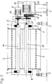
- the vibration drive shown in Figures 1 to 3 is on a sieving machine with a sieve box 1, sieve covers 2 and elastic bearings 3 attached.
- the actual vibration drive consists of two imbalances 7, 8, the unbalanced shafts or eccentric shafts 14, 15 am Sieve box 1 are stored.
- the drive of these eccentric shafts 14, 15 takes place via cardan shafts 5, 6, that of motors 9, 10 are driven on a stationary engine console are supported.
- the cardan shafts 5, 6 and thus also the eccentric shafts 14, 15 are synchronized, using synchronous waves 11, the belts 12, 13 with the motor drives 9, 10 are connected.
- the engine console 20 is on an engine stand 4 arranged. Furthermore, an eccentric shaft sits on both sides 14 or 15 an unbalance 7 or 8.
- the eccentric shafts 14, 15 as close as possible to the center of mass 16 of the screening machine are arranged.
- the unbalances 7 and 8 continue to rotate opposite and it results from the force diagram a swinging movement of the screen box according to the illustrated Ellipse (Fig. 1 and 5), the main swing direction 18 coincides with the longitudinal axis 19 of the ellipse 21.
- the connecting line through the center of the eccentric shafts 14, 15 is the Zero line 17, where in addition the resultant of the mass vibratory forces is the least.
- the angle ⁇ between them Line 17 and line 18 is preferably 90 °, being still satisfactory results in the range up to 60 ° can be achieved.
- the unbalances 7, 8 are on the Zero line 17, i.e. the line connecting the axes of the eccentric shafts 14, 15, facing each other, i.e. against each other by 180 ° twisted so that no angular accelerations or Angular delays of the unbalanced masses occur.
- the synchronization takes place of the two cardan shafts 5, 6 via a single one Synchronizer shaft 11 and a single belt 12 of the motors 9, 10 and the synchronous shaft 11 connects.
- FIG. 5 shows the force diagram.
- the two dashed circles symbolize the circumferential unbalance 8 or 7, with the unbalance 7 shown in two dimensions is, namely as a smaller unbalance 7 and dash-dotted as greater unbalance 7 '. Accordingly, there is a Ellipse 21 or an ellipse 21 'for the larger unbalance 7'.
- the resultant can be calculated using the parallelogram of forces generate whose locus is the ellipse 21.
- Some points of the Unbalance positions are shown, namely points 0 to 6 or 0 'to 6'. From the illustration it can easily be seen that the angle between the large ellipse axis 19 and the zero line 17 is 90 °.
- the mass forces can be changed by changing the unbalance set the required shape, as well as the angular position Main vibration direction 18, either manually or electrically.
- the synchronization of the two eccentric shafts 14, 15 can also through an electrical synchronization synchronization control respectively.
- the eccentric shafts 14, 15 can also be provided with a countershaft drive, with the appropriate drive belts then are attached between the countershafts.
Landscapes
- Engineering & Computer Science (AREA)
- Mechanical Engineering (AREA)
- Apparatuses For Generation Of Mechanical Vibrations (AREA)
- Combined Means For Separation Of Solids (AREA)
- Testing Of Devices, Machine Parts, Or Other Structures Thereof (AREA)
- Measurement Of Mechanical Vibrations Or Ultrasonic Waves (AREA)
Abstract
Description
- Fig. 1
- eine Siebmaschine mit einem Schwingungsantrieb nach der Erfindung im Aufriß bei einer Stellung der Unwuchten in Richtung der kleinen Ellipsenachse nach dem Kräftediagramm,
- Fig. 2
- eine Seitenansicht von Fig. 1,
- Fig. 3
- eine Ansicht der Motorkonsole mit den verschiedenen Antriebsaggregaten gemäß Fig. 1,
- Fig. 4
- eine entsprechende Ansicht der Motorkonsole gemäß einer weiteren Ausführungsform für die Antriebsaggregate, und
- Fig. 5
- das Kräftediagramm für den dargestellten Schwingungsantrieb.
Claims (8)
- Siebmaschine zum Entwässern und/oder Klassieren von körnigen Stoffen wie Kies, Kohle oder Erz, mit einem Siebrahmen (1), der an einem Maschinengestell gehalten ist, und mit einem elliptischen Schwingungsantrieb mit zwei Exzenterwellen (14, 15), die unterschiedliche Unwuchten (7, 8) aufweisen, und die synchron und gegenläufig mittels des Antriebs angetrieben werden,
dadurch gekennzeichnet, daß
daß die Resultierende der Massenkräfte der Unwuchten (7, 8) in dem Massenschwerpunkt (16) der Siebmaschine oder in dessen unmittelbarer Nähe angreift, und daß die radiale Verbindungslinie (17) der Exzenterwellen (14, 15) mit der großen Achse (19) der Schwingungsellipse (21) einen Winkel α von 60° bis 90° einschließt. - Schwingungsantrieb nach Anspruch 1,
dadurch gekennzeichnet, daß
die Massenkräfte der Unwuchten (7, 8) einstellbar sind. - Schwingungsantrieb nach Anspruch 1 und 2,
dadurch gekennzeichnet, daß
die Exzenterwellen (14, 15) mittels Keil- oder Zahnriemen (12, 13) synchronisiert sind. - Schwingungsantrieb nach Anspruch 3,
dadurch gekennzeichnet, daß
die Keil- oder Zahnriemen (12, 13) an einer Motorkonsole (20) stationär zwischen den Motoren (9, 10) angebracht sind. - Schwingungsantrieb nach Anspruch 3,
dadurch gekennzeichnet, daß
die Exzenterwellen (14, 15) über Vorgelege angetrieben sind, wobei die Riemen (12, 13) zwischen den Vorgelegewellen angebracht sind. - Schwingungsantrieb nach Anspruch 1 oder 2,
dadurch gekennzeichnet, daß
die Sunchronisation über eine elektrische Synchronisationsgleichlaufsteuerung erfolgt. - Schwingungsantrieb nach einem der Ansprüche 1 bis 6,
dadurch gekennzeichnet, daß
die Schwingrichtung und Form der Unwuchtmasse in Größe und Winkellage zur Hauptschwingrichtung (18) durch manuelle oder elektrische Verstellung von einer oder beider Exzenterwellen (14, 15) veränderbar ist. - Schwingungsantrieb nach den Ansprüchen 3 bis 5,
dadurch gekennzeichnet, daß
an der Motorkonsole (20) eine oder zwei Synchronwellen (11) gelagert sind, über die die Gelenkwellen (5, 6) der Motoren (9, 10) mittels der Riemen (12, 13) verbunden sind.
Applications Claiming Priority (2)
| Application Number | Priority Date | Filing Date | Title |
|---|---|---|---|
| DE19631849A DE19631849C1 (de) | 1996-08-07 | 1996-08-07 | Schwingungsantrieb für eine Siebmaschine |
| DE19631849 | 1996-08-07 |
Publications (3)
| Publication Number | Publication Date |
|---|---|
| EP0823291A2 true EP0823291A2 (de) | 1998-02-11 |
| EP0823291A3 EP0823291A3 (de) | 1999-01-13 |
| EP0823291B1 EP0823291B1 (de) | 2005-11-09 |
Family
ID=7802009
Family Applications (1)
| Application Number | Title | Priority Date | Filing Date |
|---|---|---|---|
| EP97113308A Expired - Lifetime EP0823291B1 (de) | 1996-08-07 | 1997-08-01 | Schwingungsantrieb für eine Siebmaschine |
Country Status (5)
| Country | Link |
|---|---|
| US (1) | US5984107A (de) |
| EP (1) | EP0823291B1 (de) |
| AT (1) | ATE309055T1 (de) |
| AU (1) | AU719552B2 (de) |
| DE (2) | DE19631849C1 (de) |
Cited By (2)
| Publication number | Priority date | Publication date | Assignee | Title |
|---|---|---|---|---|
| CN103121008A (zh) * | 2012-06-07 | 2013-05-29 | 上海智城分析仪器制造有限公司 | 培养振荡器的平面连杆悬臂式往复振荡机构 |
| CN103769365A (zh) * | 2014-01-21 | 2014-05-07 | 成都西部石油装备有限公司 | 一种新型自同步双电机安装形式的振动筛 |
Families Citing this family (29)
| Publication number | Priority date | Publication date | Assignee | Title |
|---|---|---|---|---|
| US6152307A (en) | 1993-04-30 | 2000-11-28 | Tuboscope I/P, Inc. | Vibratory separator screens |
| US6450345B1 (en) | 1993-04-30 | 2002-09-17 | Varco I/P, Inc. | Glue pattern screens and methods of production |
| US6443310B1 (en) | 1993-04-30 | 2002-09-03 | Varco I/P, Inc. | Seal screen structure |
| US6325216B1 (en) | 1993-04-30 | 2001-12-04 | Tuboscope I/P, Inc. | Screen apparatus for vibratory separator |
| US6269953B1 (en) | 1993-04-30 | 2001-08-07 | Tuboscope I/P, Inc. | Vibratory separator screen assemblies |
| US6401934B1 (en) | 1993-04-30 | 2002-06-11 | Tuboscope I/P, Inc. | Ramped screen & vibratory separator system |
| US6371302B1 (en) | 1993-04-30 | 2002-04-16 | Tuboscope I/P, Inc. | Vibratory separator screens |
| US6186337B1 (en) | 1998-10-30 | 2001-02-13 | Tuboscope I/P, Inc. | Dual screen element having upper scalping screen adhered to crests of corrugated lower screen |
| US6267247B1 (en) | 1993-04-30 | 2001-07-31 | Tuboscope I/P, Inc. | Vibratory separator screen |
| US6565698B1 (en) | 1993-04-30 | 2003-05-20 | Varco I/P, Inc. | Method for making vibratory separator screens |
| US6290068B1 (en) | 1993-04-30 | 2001-09-18 | Tuboscope I/P, Inc. | Shaker screens and methods of use |
| US6283302B1 (en) | 1993-08-12 | 2001-09-04 | Tuboscope I/P, Inc. | Unibody screen structure |
| US6932883B2 (en) | 1998-10-30 | 2005-08-23 | Varco I/P, Inc. | Screens for vibratory separators |
| US6736270B2 (en) | 1998-10-30 | 2004-05-18 | Varco I/P, Inc. | Glued screens for shale shakers |
| US20040007508A1 (en) | 1999-12-04 | 2004-01-15 | Schulte David L. | Screen assembly for vibratory separator |
| DE10117455A1 (de) * | 2001-04-06 | 2002-11-07 | Rexroth Indramat Gmbh | Verfahren zum synchronisierten Betrieb von Maschinen mit durch Einzelantriebe angetriebenen Achsen |
| CA2484970A1 (en) | 2002-05-03 | 2003-11-13 | General Kinematics Corporation | Vibratory sand reclaiming apparatus having normal and reject modes |
| WO2008035214A2 (en) * | 2006-06-21 | 2008-03-27 | W.S. Tylinter | Screen assembly for separating material according to particle size |
| BRPI0910673A2 (pt) * | 2008-04-22 | 2018-03-27 | Mi Llc | separador vibratório |
| US20100206782A1 (en) * | 2009-02-17 | 2010-08-19 | Metso Minerals Industries, Inc. | Cone lip assembly |
| AT14201U1 (de) * | 2013-11-15 | 2015-05-15 | Binder Co Ag | Siebmaschine mit Antrieb |
| DE102015104041B4 (de) | 2015-03-18 | 2020-09-10 | Rhewum Gmbh | Siebmaschine |
| EP3165290B1 (de) | 2015-11-06 | 2021-04-07 | BAUER Maschinen GmbH | Schwingungserzeuger und verfahren zum einbringen eines rammgutes in einen boden |
| GB201617106D0 (en) * | 2016-10-07 | 2016-11-23 | Bailey Marshall G | Screening apparatus |
| CN107497681A (zh) * | 2017-08-19 | 2017-12-22 | 益阳胜希机械设备制造有限公司 | 一种小吊筛机 |
| CN108188013B (zh) * | 2017-12-22 | 2023-09-05 | 洛阳理工学院 | 一种具有多种振动轨迹的振动筛 |
| CN108855911B (zh) * | 2018-06-12 | 2021-02-02 | 长乐智睿恒创节能科技有限责任公司 | 一种节能型双层振动筛 |
| CN112207025B (zh) * | 2020-10-13 | 2022-04-22 | 神木市亿通煤化有限公司 | 一种可控制填料量的选矿用多级筛分装置 |
| CN112974223A (zh) * | 2021-02-07 | 2021-06-18 | 中海油田服务股份有限公司 | 一种分选振动筛和干湿分料设备 |
Family Cites Families (10)
| Publication number | Priority date | Publication date | Assignee | Title |
|---|---|---|---|---|
| US3053379A (en) * | 1956-06-21 | 1962-09-11 | Schenck Gmbh Carl | Material handling vibrating machine |
| US3226989A (en) * | 1961-11-07 | 1966-01-04 | Litton Industries Inc | Vibratory screen systems |
| US3704631A (en) * | 1971-07-21 | 1972-12-05 | Rex Chainbelt Inc | Adjustable phase two shaft vibrator |
| US4196637A (en) * | 1975-06-16 | 1980-04-08 | Babbitless | Vibratory device with controlled actuation |
| FR2355576A2 (fr) * | 1976-06-21 | 1978-01-20 | Babbitless Sa | Dispositif vibrant a action dirigee |
| DE2630458A1 (de) * | 1976-07-07 | 1978-01-12 | Pohlig Heckel Bleichert | Antreibbares vibrationsgetriebe |
| DE7811967U1 (de) * | 1978-04-20 | 1978-08-17 | Ibag Vertrieb Gmbh, 6730 Neustadt | Antrieb fuer schwingmaschinen |
| US4340469A (en) * | 1981-01-23 | 1982-07-20 | Spokane Crusher Mfg. Co. | Vibratory screen apparatus |
| US4529510A (en) * | 1982-11-15 | 1985-07-16 | Johnson Louis W | Shaker screen |
| GB9210624D0 (en) * | 1992-05-19 | 1992-07-01 | Alfa Laval Separation Ab | Vibratory screening apparatus |
-
1996
- 1996-08-07 DE DE19631849A patent/DE19631849C1/de not_active Expired - Fee Related
-
1997
- 1997-08-01 DE DE59712474T patent/DE59712474D1/de not_active Expired - Fee Related
- 1997-08-01 AT AT97113308T patent/ATE309055T1/de not_active IP Right Cessation
- 1997-08-01 EP EP97113308A patent/EP0823291B1/de not_active Expired - Lifetime
- 1997-08-04 AU AU32468/97A patent/AU719552B2/en not_active Ceased
- 1997-08-06 US US08/906,931 patent/US5984107A/en not_active Expired - Fee Related
Cited By (3)
| Publication number | Priority date | Publication date | Assignee | Title |
|---|---|---|---|---|
| CN103121008A (zh) * | 2012-06-07 | 2013-05-29 | 上海智城分析仪器制造有限公司 | 培养振荡器的平面连杆悬臂式往复振荡机构 |
| CN103769365A (zh) * | 2014-01-21 | 2014-05-07 | 成都西部石油装备有限公司 | 一种新型自同步双电机安装形式的振动筛 |
| CN103769365B (zh) * | 2014-01-21 | 2015-09-30 | 成都西部石油装备股份有限公司 | 一种新型自同步双电机安装形式的振动筛 |
Also Published As
| Publication number | Publication date |
|---|---|
| AU719552B2 (en) | 2000-05-11 |
| EP0823291A3 (de) | 1999-01-13 |
| DE19631849C1 (de) | 1998-01-08 |
| DE59712474D1 (de) | 2005-12-15 |
| AU3246897A (en) | 1998-02-12 |
| US5984107A (en) | 1999-11-16 |
| EP0823291B1 (de) | 2005-11-09 |
| ATE309055T1 (de) | 2005-11-15 |
Similar Documents
| Publication | Publication Date | Title |
|---|---|---|
| EP0823291B1 (de) | Schwingungsantrieb für eine Siebmaschine | |
| DE4019304C1 (de) | ||
| DE102009055950A1 (de) | Verdichtungsgerät, sowie Verfahren zum Verdichten von Böden | |
| EP2105214A1 (de) | Schwingungserzeuger | |
| EP2105213B1 (de) | Schwingungserzeuger | |
| AT517133B1 (de) | Entkernmaschine/Rüttelmaschine mit verbessertem Antrieb | |
| EP3789126A1 (de) | Regelbare siebmaschine | |
| DE2461101A1 (de) | Ruettelsieb | |
| EP0980292A1 (de) | Vorrichtung zum erzeugen gerichteter schwingungen | |
| DE3708922A1 (de) | Vorrichtung zum herstellen von betonteilen | |
| EP2392413A2 (de) | Vibrationsramme | |
| EP0218575A2 (de) | Siebvorrichtung | |
| EP0734786A1 (de) | Rüttelvorrichtung für den Rütteltisch einer Steinformmaschine | |
| DE19953553A1 (de) | Bodenverdichter mit stufenlos verstellbarer Schwingungsamplitude | |
| DE3727742C1 (de) | Schuettelbock | |
| DE2528269A1 (de) | Vorrichtung zur synchronisierung zweier im gegensinn laufender unwuchtantriebe | |
| DE4106443A1 (de) | Vibrationsmaschine | |
| DE3607189A1 (de) | Schwingungserzeugender antrieb fuer eine siebmaschine | |
| DE3642487A1 (de) | Einrichtung zum ausgleich von wechselmomenten | |
| DE4138476C1 (en) | Mass equaliser for flat screening machines - has eccentric drive firmly coupled to main frame, or foundation, also contg. equalising weight | |
| EP0824971B1 (de) | Schwingungserreger | |
| DE4224113A1 (de) | Schwingungserreger | |
| DE580487C (de) | Einrichtung zum Beseitigen oder Daempfen von Schwingungen aller Art | |
| DE202007018292U1 (de) | Schwingungsantrieb | |
| DE19508243A1 (de) | Rüttelvorrichtung |
Legal Events
| Date | Code | Title | Description |
|---|---|---|---|
| PUAI | Public reference made under article 153(3) epc to a published international application that has entered the european phase |
Free format text: ORIGINAL CODE: 0009012 |
|
| AK | Designated contracting states |
Kind code of ref document: A2 Designated state(s): AT DE ES FI FR GB IT SE |
|
| AX | Request for extension of the european patent |
Free format text: AL;LT;LV;RO;SI |
|
| PUAL | Search report despatched |
Free format text: ORIGINAL CODE: 0009013 |
|
| AK | Designated contracting states |
Kind code of ref document: A3 Designated state(s): AT BE CH DE DK ES FI FR GB GR IE IT LI LU MC NL PT SE |
|
| AX | Request for extension of the european patent |
Free format text: AL;LT;LV;RO;SI |
|
| 17P | Request for examination filed |
Effective date: 19990707 |
|
| AKX | Designation fees paid |
Free format text: AT DE ES FI FR GB IT SE |
|
| 17Q | First examination report despatched |
Effective date: 20000811 |
|
| 18R | Application refused |
Effective date: 20020502 |
|
| D18R | Application refused (deleted) | ||
| D18R | Application refused (deleted) | ||
| APBN | Date of receipt of notice of appeal recorded |
Free format text: ORIGINAL CODE: EPIDOSNNOA2E |
|
| APBT | Appeal procedure closed |
Free format text: ORIGINAL CODE: EPIDOSNNOA9E |
|
| GRAP | Despatch of communication of intention to grant a patent |
Free format text: ORIGINAL CODE: EPIDOSNIGR1 |
|
| APAA | Appeal reference recorded |
Free format text: ORIGINAL CODE: EPIDOS REFN |
|
| GRAS | Grant fee paid |
Free format text: ORIGINAL CODE: EPIDOSNIGR3 |
|
| GRAA | (expected) grant |
Free format text: ORIGINAL CODE: 0009210 |
|
| APAH | Appeal reference modified |
Free format text: ORIGINAL CODE: EPIDOSCREFNO |
|
| AK | Designated contracting states |
Kind code of ref document: B1 Designated state(s): AT DE ES FI FR GB IT SE |
|
| PG25 | Lapsed in a contracting state [announced via postgrant information from national office to epo] |
Ref country code: IT Free format text: LAPSE BECAUSE OF FAILURE TO SUBMIT A TRANSLATION OF THE DESCRIPTION OR TO PAY THE FEE WITHIN THE PRE;WARNING: LAPSES OF ITALIAN PATENTS WITH EFFECTIVE DATE BEFORE 2007 MAY HAVE OCCURRED AT ANY TIME BEFORE 2007. THE CORRECT EFFECTIVE DATE MAY BE DIFFERENT FROM THE ONE RECORDED.SCRIBED TIME-LIMIT Effective date: 20051109 Ref country code: GB Free format text: LAPSE BECAUSE OF FAILURE TO SUBMIT A TRANSLATION OF THE DESCRIPTION OR TO PAY THE FEE WITHIN THE PRESCRIBED TIME-LIMIT Effective date: 20051109 |
|
| APAJ | Date of receipt of notice of appeal modified |
Free format text: ORIGINAL CODE: EPIDOSCNOA2O |
|
| REF | Corresponds to: |
Ref document number: 59712474 Country of ref document: DE Date of ref document: 20051215 Kind code of ref document: P |
|
| PG25 | Lapsed in a contracting state [announced via postgrant information from national office to epo] |
Ref country code: SE Free format text: LAPSE BECAUSE OF FAILURE TO SUBMIT A TRANSLATION OF THE DESCRIPTION OR TO PAY THE FEE WITHIN THE PRESCRIBED TIME-LIMIT Effective date: 20060209 |
|
| PG25 | Lapsed in a contracting state [announced via postgrant information from national office to epo] |
Ref country code: ES Free format text: LAPSE BECAUSE OF FAILURE TO SUBMIT A TRANSLATION OF THE DESCRIPTION OR TO PAY THE FEE WITHIN THE PRESCRIBED TIME-LIMIT Effective date: 20060220 |
|
| GBV | Gb: ep patent (uk) treated as always having been void in accordance with gb section 77(7)/1977 [no translation filed] |
Effective date: 20051109 |
|
| PLBE | No opposition filed within time limit |
Free format text: ORIGINAL CODE: 0009261 |
|
| STAA | Information on the status of an ep patent application or granted ep patent |
Free format text: STATUS: NO OPPOSITION FILED WITHIN TIME LIMIT |
|
| 26N | No opposition filed |
Effective date: 20060810 |
|
| PG25 | Lapsed in a contracting state [announced via postgrant information from national office to epo] |
Ref country code: FR Free format text: LAPSE BECAUSE OF FAILURE TO SUBMIT A TRANSLATION OF THE DESCRIPTION OR TO PAY THE FEE WITHIN THE PRESCRIBED TIME-LIMIT Effective date: 20061020 |
|
| EN | Fr: translation not filed | ||
| PG25 | Lapsed in a contracting state [announced via postgrant information from national office to epo] |
Ref country code: DE Free format text: LAPSE BECAUSE OF NON-PAYMENT OF DUE FEES Effective date: 20070301 |
|
| PG25 | Lapsed in a contracting state [announced via postgrant information from national office to epo] |
Ref country code: AT Free format text: LAPSE BECAUSE OF NON-PAYMENT OF DUE FEES Effective date: 20060801 |
|
| PG25 | Lapsed in a contracting state [announced via postgrant information from national office to epo] |
Ref country code: FI Free format text: LAPSE BECAUSE OF FAILURE TO SUBMIT A TRANSLATION OF THE DESCRIPTION OR TO PAY THE FEE WITHIN THE PRESCRIBED TIME-LIMIT Effective date: 20051109 |
|
| PG25 | Lapsed in a contracting state [announced via postgrant information from national office to epo] |
Ref country code: FR Free format text: LAPSE BECAUSE OF FAILURE TO SUBMIT A TRANSLATION OF THE DESCRIPTION OR TO PAY THE FEE WITHIN THE PRESCRIBED TIME-LIMIT Effective date: 20051109 |