EP0822111A2 - Drehbewegungs-Übertragungsmechanismus und damit versehene Verteilervorrichtung für Kraftfahrzeug - Google Patents
Drehbewegungs-Übertragungsmechanismus und damit versehene Verteilervorrichtung für Kraftfahrzeug Download PDFInfo
- Publication number
- EP0822111A2 EP0822111A2 EP97113349A EP97113349A EP0822111A2 EP 0822111 A2 EP0822111 A2 EP 0822111A2 EP 97113349 A EP97113349 A EP 97113349A EP 97113349 A EP97113349 A EP 97113349A EP 0822111 A2 EP0822111 A2 EP 0822111A2
- Authority
- EP
- European Patent Office
- Prior art keywords
- rotational
- rollers
- pressing
- rotary elements
- transmitting mechanism
- Prior art date
- Legal status (The legal status is an assumption and is not a legal conclusion. Google has not performed a legal analysis and makes no representation as to the accuracy of the status listed.)
- Withdrawn
Links
Images


Classifications
-
- B—PERFORMING OPERATIONS; TRANSPORTING
- B60—VEHICLES IN GENERAL
- B60K—ARRANGEMENT OR MOUNTING OF PROPULSION UNITS OR OF TRANSMISSIONS IN VEHICLES; ARRANGEMENT OR MOUNTING OF PLURAL DIVERSE PRIME-MOVERS IN VEHICLES; AUXILIARY DRIVES FOR VEHICLES; INSTRUMENTATION OR DASHBOARDS FOR VEHICLES; ARRANGEMENTS IN CONNECTION WITH COOLING, AIR INTAKE, GAS EXHAUST OR FUEL SUPPLY OF PROPULSION UNITS IN VEHICLES
- B60K17/00—Arrangement or mounting of transmissions in vehicles
- B60K17/04—Arrangement or mounting of transmissions in vehicles characterised by arrangement, location, or kind of gearing
- B60K17/16—Arrangement or mounting of transmissions in vehicles characterised by arrangement, location, or kind of gearing of differential gearing
-
- F—MECHANICAL ENGINEERING; LIGHTING; HEATING; WEAPONS; BLASTING
- F16—ENGINEERING ELEMENTS AND UNITS; GENERAL MEASURES FOR PRODUCING AND MAINTAINING EFFECTIVE FUNCTIONING OF MACHINES OR INSTALLATIONS; THERMAL INSULATION IN GENERAL
- F16D—COUPLINGS FOR TRANSMITTING ROTATION; CLUTCHES; BRAKES
- F16D41/00—Freewheels or freewheel clutches
- F16D41/06—Freewheels or freewheel clutches with intermediate wedging coupling members between an inner and an outer surface
- F16D41/061—Freewheels or freewheel clutches with intermediate wedging coupling members between an inner and an outer surface the intermediate members wedging by movement having an axial component
-
- B—PERFORMING OPERATIONS; TRANSPORTING
- B60—VEHICLES IN GENERAL
- B60K—ARRANGEMENT OR MOUNTING OF PROPULSION UNITS OR OF TRANSMISSIONS IN VEHICLES; ARRANGEMENT OR MOUNTING OF PLURAL DIVERSE PRIME-MOVERS IN VEHICLES; AUXILIARY DRIVES FOR VEHICLES; INSTRUMENTATION OR DASHBOARDS FOR VEHICLES; ARRANGEMENTS IN CONNECTION WITH COOLING, AIR INTAKE, GAS EXHAUST OR FUEL SUPPLY OF PROPULSION UNITS IN VEHICLES
- B60K17/00—Arrangement or mounting of transmissions in vehicles
- B60K17/34—Arrangement or mounting of transmissions in vehicles for driving both front and rear wheels, e.g. four wheel drive vehicles
- B60K17/348—Arrangement or mounting of transmissions in vehicles for driving both front and rear wheels, e.g. four wheel drive vehicles having differential means for driving one set of wheels, e.g. the front, at one speed and the other set, e.g. the rear, at a different speed
-
- F—MECHANICAL ENGINEERING; LIGHTING; HEATING; WEAPONS; BLASTING
- F16—ENGINEERING ELEMENTS AND UNITS; GENERAL MEASURES FOR PRODUCING AND MAINTAINING EFFECTIVE FUNCTIONING OF MACHINES OR INSTALLATIONS; THERMAL INSULATION IN GENERAL
- F16D—COUPLINGS FOR TRANSMITTING ROTATION; CLUTCHES; BRAKES
- F16D15/00—Clutches with wedging balls or rollers or with other wedgeable separate clutching members
-
- F—MECHANICAL ENGINEERING; LIGHTING; HEATING; WEAPONS; BLASTING
- F16—ENGINEERING ELEMENTS AND UNITS; GENERAL MEASURES FOR PRODUCING AND MAINTAINING EFFECTIVE FUNCTIONING OF MACHINES OR INSTALLATIONS; THERMAL INSULATION IN GENERAL
- F16D—COUPLINGS FOR TRANSMITTING ROTATION; CLUTCHES; BRAKES
- F16D41/00—Freewheels or freewheel clutches
- F16D41/06—Freewheels or freewheel clutches with intermediate wedging coupling members between an inner and an outer surface
- F16D41/064—Freewheels or freewheel clutches with intermediate wedging coupling members between an inner and an outer surface the intermediate members wedging by rolling and having a circular cross-section, e.g. balls
-
- F—MECHANICAL ENGINEERING; LIGHTING; HEATING; WEAPONS; BLASTING
- F16—ENGINEERING ELEMENTS AND UNITS; GENERAL MEASURES FOR PRODUCING AND MAINTAINING EFFECTIVE FUNCTIONING OF MACHINES OR INSTALLATIONS; THERMAL INSULATION IN GENERAL
- F16D—COUPLINGS FOR TRANSMITTING ROTATION; CLUTCHES; BRAKES
- F16D43/00—Automatic clutches
- F16D43/28—Automatic clutches actuated by fluid pressure
- F16D43/284—Automatic clutches actuated by fluid pressure controlled by angular speed
-
- F—MECHANICAL ENGINEERING; LIGHTING; HEATING; WEAPONS; BLASTING
- F16—ENGINEERING ELEMENTS AND UNITS; GENERAL MEASURES FOR PRODUCING AND MAINTAINING EFFECTIVE FUNCTIONING OF MACHINES OR INSTALLATIONS; THERMAL INSULATION IN GENERAL
- F16D—COUPLINGS FOR TRANSMITTING ROTATION; CLUTCHES; BRAKES
- F16D7/00—Slip couplings, e.g. slipping on overload, for absorbing shock
- F16D7/007—Slip couplings, e.g. slipping on overload, for absorbing shock the torque being transmitted and limited by rolling surfaces skidding, e.g. skew needle rollers
-
- B—PERFORMING OPERATIONS; TRANSPORTING
- B60—VEHICLES IN GENERAL
- B60K—ARRANGEMENT OR MOUNTING OF PROPULSION UNITS OR OF TRANSMISSIONS IN VEHICLES; ARRANGEMENT OR MOUNTING OF PLURAL DIVERSE PRIME-MOVERS IN VEHICLES; AUXILIARY DRIVES FOR VEHICLES; INSTRUMENTATION OR DASHBOARDS FOR VEHICLES; ARRANGEMENTS IN CONNECTION WITH COOLING, AIR INTAKE, GAS EXHAUST OR FUEL SUPPLY OF PROPULSION UNITS IN VEHICLES
- B60K17/00—Arrangement or mounting of transmissions in vehicles
- B60K17/34—Arrangement or mounting of transmissions in vehicles for driving both front and rear wheels, e.g. four wheel drive vehicles
- B60K17/342—Arrangement or mounting of transmissions in vehicles for driving both front and rear wheels, e.g. four wheel drive vehicles having a longitudinal, endless element, e.g. belt or chain, for transmitting drive to wheels
Definitions
- the present invention relates to a rotation transmitting mechanism effective for various mechanical apparatuses and to an automotive transfer using the rotation transmitting mechanism.
- Hitherto known as this type of rotation transmitting mechanism is one having a multiplicity of first clutch disks fixed to a shaft coupled to the exterior and a multiplicity of second clutch disks connected to a casing, the first and second clutch disks alternately confronting one another, in which when a relative rotational difference occurs between the shaft and the casing, the clutch disks are pressed by the hydraulic pump or the like located on one end side of the clutch disks, to generate a frictional force for the transmission of a power.
- This rotation transmitting mechanism can be used to couple the automobile front and rear wheel drive shafts to thereby transmit a power to the coupled drive wheels in case the main driving side drive wheels are in idle, so that an easy escape is ensured even though one of the front wheels or the rear wheels has run up onto a surface of road having a lower frictional coefficient.
- the present invention was conceived in view of the above problems. It is therefore the object of the present invention to provide a rotation transmitting mechanism capable of always and stably transmitting a power irrespective of rotational speed ranging from low speed rotation to high speed rotation, and a transfer for automobiles using the rotation transmitting mechanism.
- a rotation transmitting mechanism having a pair of rotary elements arranged coaxially with each other, a movable member engaged with one rotary element in an axially displaceable manner and rotating together with said one rotary element, pressing means for pressing said movable member toward its one end in the axial direction, and rotational force transmission means for transmitting rotational forces of said rotary elements by use of pressing force of said pressing means
- said rotational force transmission means comprise a rotational member which rotates together with said one rotary element, a rotational member which rotates together with the other rotary element, a plurality of rollers arranged spaced apart from one another in the circumferential direction of the rotary elements between axially confronting surfaces of said rotational members, said plurality of rollers being allowed, when a rotational difference occurs between said rotary elements, to roll while being in contact with said axially confronting surfaces of said rotational members, and a roller retainer for retaining said roller
- the rollers are allowed to roll while being in contact with both a surface rotating together with one rotary element and a surface rotating together with the other rotary element.
- the rollers move along rotational paths of the rotary elements while being restricted by the roller retainer from rolling in the direction inclined by a predetermined angle relative to the rotational paths of the rotary elements, so that when the movable member is pressed by the pressing means toward the rollers, between the rollers and the contact surfaces therewith there is generated a friction force corresponding to the pressing force of the movable member, the frictional force resulting in a resistance for the transmission of power.
- the rollers generate a sliding friction while rolling, thus ensuring an acquisition of constantly stabilized frictional force.
- it is possible to transmit a power in a constantly stabilized manner irrespective of rotational speed ranging from a lower speed rotation to a higher speed rotation, and to eliminate the influence of a change in temperature, thus ensuring a secure prevention of occurrence of noise or vibration at a lower speed rotation by the stick slip, which would be very advantageous for use in e.g. the power transmission line of the automobile.
- said rollers are provided in a freely inclined manner so that a first angle is different from a second angle, said first angle being an angle formed, when a rotational difference of said rotary elements occurs in one rotational direction, between the rolling axes of said rollers and a plane containing the rotational axes of said rotary elements, said second angle being an angle formed, when said rotary elements generate a rotational difference in the other rotational direction, between the rolling axes of said rollers and a plane containing the rotational axes of said rotary elements, whereby the inclination angles of the rollers in the rotational directions are varied, making it possible to increase the power transmission force when the rotational difference between the rotary elements occurs in one rotational direction, but to reduce the power transmission force when it occurs in the other rotational direction.
- said pressing means comprise a viscous fluid arranged on the other end of said movable member, and a pressing member for imparting to said viscous fluid a pressure in the axial direction of said movable member by a rotational force of said one rotary element, whereby a power of one rotary element is transmitted to the other rotary element at a magnitude corresponding to the rotational speed difference.
- said pressing means comprise a pressing member arranged on the other end side of said movable member, driving means capable of displacing said pressing member in the axial direction of said movable member, and control means for optionally varying the pressing force imparted by said drive means to said movable member, whereby it is possible to optionally vary the power transmission force of the rotary elements.
- the roller retainer may have a hole for receiving a plurality of rollers, thereby allowing the rollers within the hole to individually roll to generate a more stable frictional force.
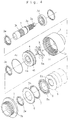
- the rotation transmitting mechanism comprises a casing 1, a casing cover 2 for closing one end of the casing 1, a shaft 3 arranged coaxially with the casing 1, a piston disk 4 connected axially displaceably to the casing 1, a plurality of pressure plates 5, 6 arranged on one end surface side of the piston disk 4 so as to alternately confront one another in the axial direction of the casing 1, a multiplicity of rollers 7 arranged circumferentially between the pressure plates 5 and 6, a plurality of cages 8 for retaining the rollers 7 in a spaced apart relationship, and a pressure rotor 9 arranged on the other end surface side of the piston disk 4 and joined axially displaceably to the shaft 3, with the pressure rotor 9 having a viscous fluid 10 filled therearound.
- the casing 1 and the casing cover 2 constitute one rotary element, the shaft 3, the piston disk 4, the pressure plates 5, 6, the rollers 7, the cage 8 and the pressure rotor 9 serving respectively as the other rotary element, a movable member, rotational member, rolling elements, a roller retainer and a pressing member.
- Pressing means are comprised of the pressure rotor 9 and the viscous fluid 10, with rotational force transmission means being comprised of the pressure plates 5, 6, the rollers 7 and the cage 8.
- the casing 1 is in the form of a cylinder having one open end and the other end provided at its center with a bearing 1a supporting the shaft 3. On the inner peripheral surface of the casing 1 there are formed key grooves 1b and 1c with which the piston disk 4 and the pressure plates 5 on one hand axially displaceably engage.
- the casing 1 includes a filling hole 1d into the interior of which the viscous fluid 10 is filled, the filling hole 1d being intended to be blocked by a ball 1e after filling of the viscous fluid 10.
- at least two filling holes 1d are provided for injection and for air venting.
- the casing cover 2 is in the form of a disk so as to block one end of the casing 1 and is provided at its center with a bearing 2a for supporting the shaft 3.
- the external surface of the casing cover 2 is provided with a splined connection 2b intended to be connected to one driving system not shown.
- the shaft 3 has at its one end a connection 3a intended to be connected to the one driving system not shown, with the peripheral surface being at two locations a spline 3b with which pressure plates 6 on the other axially displaceably engage and a spline 3c with which the pressure rotor 9 axially displaceably engage.
- the shaft 3 is supported by way of a bearing 3d on the casing 1, with an oil seal 3e serving to seal gaps which may be defined between the shaft 3 and the bearing 1a of the casing 1, the bearing 2a of the casing cover 2 and the piston disk 4.
- the piston disk 4 is shaped into a disk having at its center a hole 4a through which the shaft 3 rotatably extends.
- the outer peripheral surface of the piston disk 4 is formed with an axially extending spline 4b with which the key groove 1c of the casing 1 is enaged to thereby allow the piston disk 4 to be axially displaceably mounted on the casing 1.
- An O-ring 4c is provided to seal a gap defined between the outer peripheral surface of the piston disk 4 and the inner peripheral surface of the casing 1.
- the pressure plates 5, 6 are each of an annular shape, with the outer periphery of the pressure plate 5 on one hand being formed with a spline 5a which is engaged with the key groove 1b of the casing 1, the inner periphery of the pressure plate 6 on the other being formed with a key groove 6a which is engaged with the spline 3b of the shaft 3.
- Each roller 7 is in the form of a uniformly extending cylinder and is interposed between the pressure plates 5, 6 associated therewith.
- Each cage 8 includes a multiplicity of holes 8a for accommodating rollers 7 in a freely rolling manner, with each hole 8a being formed so that as shown in Fig. 5B a rolling axis X of each roller 7 is inclined by an angle of theta with respect to a plane containing the rotational axis of the casing 1, that is, a line Y extending from the rotational center of the casing 1.
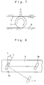
- the pressure rotor 9 has a multiplicity of radially extending protrusions 9a, with the inner peripheral surface of the centrally formed hole being provided with a key groove 9b with which the spline 3c of the shaft 3 engages.
- Each protrusion 9a has as shown in Fig. 6 an inclined surface which is inclined relative to the circumferential direction of the pressure rotor 9.
- the viscous fluid 10 may be for example silicone oil and is filled around the pressure rotor 9, that is, within a sealed region defined between the other end surface of the piston disk 4 and the inner surace of the casing 1.
- a multiplicity of rollers 7 whose rolling axes are inclined by a predetermined angle relative to a plane containing a rotational axis of the casing 1 are allowed to roll while being in pressure contact with the pressure plates 5, 6 by the pressing force of the piston disk 4 which is axially displaceable, to generate a differential restricting force by a sliding friction accompanied by rolling of the rollers 7, thereby achieving a constantly stabilized power transmission without causing a stick slip at a low rotational speed, as well as a secure prevention of occurrence of noise and vibration. It is also possible to vary the magnitude of the frictional force by arbitrarily setting the inclination angle theta of the rollers 7, thus ensuring an acquisition of a desired differential restricting force.
- a wire ring 3f may be interposed between the outer peripheral surface of the shaft 3 and the inner peripheral surface of the cage 8, to thereby preventing a direct contact of the inner peripheral surface of the cage with the spline 3b of the shaft 3, resulting in a reduction of friction which may occur on the inner peripheral surface of the cage 8.
- the wire ring 3f is made of a metal rod such as a piano wire having an elasticity which is annularly bent with a diameter smaller than the external diameter of the shaft 3. That is, the wire ring 3f is bent in such a manner that its external diameter is enlarged upon mounting onto the external periphery of the shaft 3.
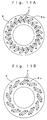
- Figs. 11A and 11B there is depicted a variant of the above embodiment, in which two rollers 7 are received in each of the holes of the cage 8. More specifically, the cage 8 shown in Fig. 11A has a hole 8b for receiving two rollers 7 which are axially arranged, whereas the cage 8 shown in Fig. 11B has a hole 8c for receiving two rollers 7 which are radially arranged.
- Such arrangements allow the rollers 7 within the hole 8b or 8c to individually roll, to thereby ensure a generation of a more stabilized frictional force as well as an acquisition of a frictional force arising from the contact of the rollers 7 with each other.
- FIGs. 12 and 13 there is depicted another variant of the above embodiment, in which the rollers 7 are provided in a freely inclined manner.
- the cage 11 shown has a multiplicity of holes 11a for receiving the rollers 7 in a freely rolling manner, with each hole 11a being shaped into a fan starting from one end of the roller 7 and having two edges which extend from the one end and are differently inclined so as to form different angles relative to a plane containing the rotational axis of the device body.
- Fig. 14 is a side sectional view of a transfer employing the rotation transmitting mechanism
- Fig. 15 is a schematic view showing a power transmission line of an automobile.
- the transfer comprises a main shaft 20 for transmitting an engine driving force to the rear wheel side of the automobile, a transfer shaft 30 connected to a drive line on the automobile front wheel side, a rotation transmitting mechanism 40 for transmitting a power from the main shaft 20 to the transfer shaft 30, and a control unit 50 for the control of the transmission power of the rotation transmitting mechanism 40.
- the main shaft 20 has at its one end a connection 20a to be connected to the engine, and at its other end a connection 20b to be connected to the rear wheel R side.
- the transfer shaft 30 is arranged parallel to the main shaft 20, and includes a connection 30a to be connected to the front wheel F side and a connection 30b to be connected to the rotation transmitting mechanism 40 side.
- the rotation transmitting mechanism 40 comprises a casing 41 which rotates together with the main shaft 20, a shaft 42 which rotates together with the transfer shaft 30, a piston disk 43 coupled to the casing 41 in such a manner as to be axially displaceable, a plurality of pressure plates 44, 45 arranged within the piston disk 43 so as to axially alternately confront one another, a multiplicity of rollers 47 arranged between the pressure plates 44 and 45, a plurality of cages 48 for retaining the rollers 47 in a freely rolling manner, and a pressing mechanism 49 for pressing the piston disk 43 in the axial direction of the casing 41.
- the pressure plate 44 on one hand rotates together with the casing 41 whereas the pressure plate 45 on the other rotates together with the shaft 42, and in the same manner as the first embodiment, the cages 48 retain the rollers 47 in such a manner that the rolling axes of the rollers 47 are inclined by a predetermined angle relative to a plane containing the rotational axis of the casing 1.
- the shaft 42 has a connection 42a to be connected to the transfer shaft 30, and is rotatably mounted on the main shaft 20. Arrangement is such that the connection 42a of the shaft 42 is coupled via a chain 42b to a connection 30b of the transfer shaft 30, to allow the shaft 42 and the transfer shaft 30 to rotate together.
- the pressing mechanism 49 comprises a support plate 49a for rotatably supporting the piston disk 43, a lever 49b for pressing the support plate 49a toward the piston disk 43, a pin 49c for pivotally supporting one end of the lever 49b, a rod 49d having one end connected to the other end of the lever 49b, a piston 49e connected to the other end of the rod 49d, and a cylinder 49f for imparting a sliding motion to the piston 49e which is driven by a hydraulic pressure within the cylinder 49f.
- the hydraulic pressure within the cylinder 49f is raised by a hydraulic pump not shown, the piston 49e slides to allow the piston disk 43 to be pressed toward the rollers 47 by means of the lever 49b.
- the control unit 50 is comprised of a microcomputer which is connected to the hydraulic pump for driving the piston 49e.
- the control unit 50 receives information on the state of travel of the automobile from a sensor for detecting the velocities of the wheels and from a sensor for detecting acceleration in the longitudinal and transverse direction of the automobile, based on which information the pressing force of the pressing mechanism 49 is controlled.
- the rotation transmitting mechanism 40 whose power transmission force is controlled by the control unit 50 is used in the automobile transfer, so that similar to the first embodiment it is possible to constantly and stably transmit a power and therefore to improve the performance of the power distributor.
- the above embodiment has been of a type making use of hydraulic pressure to drive the pressing mechanism 49 of the rotation transmitting mechanism 40, it would also be possible to employ other driving means such as a pressure generating mechanism comprised of for example an electromagnetic clutch and various hydraulic pumps.
- a pressure generating mechanism comprised of for example an electromagnetic clutch and various hydraulic pumps.
- the engine driving force has always been transmitted via the main shaft 20 to the rear wheel R side, but optionally via the transfer shaft 30 to the front wheel F side, it would also be possible to arrange reversely, that is, in such a manner that the power from the main shaft 20 is transmitted to the front wheel F side but the power associated with the transfer shaft 30 to the rear wheel R side.
Landscapes
- Engineering & Computer Science (AREA)
- General Engineering & Computer Science (AREA)
- Mechanical Engineering (AREA)
- Chemical & Material Sciences (AREA)
- Combustion & Propulsion (AREA)
- Transportation (AREA)
- Physics & Mathematics (AREA)
- Fluid Mechanics (AREA)
- Arrangement And Driving Of Transmission Devices (AREA)
- Friction Gearing (AREA)
- One-Way And Automatic Clutches, And Combinations Of Different Clutches (AREA)
Applications Claiming Priority (3)
| Application Number | Priority Date | Filing Date | Title |
|---|---|---|---|
| JP20504696 | 1996-08-02 | ||
| JP8205046A JPH1047367A (ja) | 1996-08-02 | 1996-08-02 | 回転伝動機構 |
| JP205046/96 | 1996-08-02 |
Publications (2)
| Publication Number | Publication Date |
|---|---|
| EP0822111A2 true EP0822111A2 (de) | 1998-02-04 |
| EP0822111A3 EP0822111A3 (de) | 1999-06-16 |
Family
ID=16500559
Family Applications (1)
| Application Number | Title | Priority Date | Filing Date |
|---|---|---|---|
| EP97113349A Withdrawn EP0822111A3 (de) | 1996-08-02 | 1997-08-01 | Drehbewegungs-Übertragungsmechanismus und damit versehene Verteilervorrichtung für Kraftfahrzeug |
Country Status (8)
| Country | Link |
|---|---|
| EP (1) | EP0822111A3 (de) |
| JP (1) | JPH1047367A (de) |
| KR (1) | KR100272804B1 (de) |
| CN (1) | CN1175516A (de) |
| AU (1) | AU3244497A (de) |
| CA (1) | CA2211041A1 (de) |
| ID (1) | ID17261A (de) |
| TW (1) | TW348125B (de) |
Cited By (4)
| Publication number | Priority date | Publication date | Assignee | Title |
|---|---|---|---|---|
| EP1063439A1 (de) * | 1999-06-25 | 2000-12-27 | Kenji Mimura | Reibungskupplung und ihre Verwendung in Kraftfahrzeuge und Motorräder |
| WO2010116232A1 (en) * | 2009-04-08 | 2010-10-14 | Eaton Corporation | Enhanced lubrication skewed roller clutch assembly and actuator including it |
| EP1574754A3 (de) * | 2004-03-09 | 2010-12-08 | Eaton Corporation | Kupplungsvorrichtung |
| EP3324065A1 (de) * | 2016-11-21 | 2018-05-23 | Ratier-Figeac SAS | No-back-mechanismus |
Families Citing this family (2)
| Publication number | Priority date | Publication date | Assignee | Title |
|---|---|---|---|---|
| JP2008133960A (ja) * | 2007-12-14 | 2008-06-12 | Yanmar Co Ltd | トルクリミッタ |
| CN112555297B (zh) * | 2020-11-27 | 2022-02-18 | 安徽康明斯动力有限公司 | 一种可实现高低速的传动机构 |
Family Cites Families (3)
| Publication number | Priority date | Publication date | Assignee | Title |
|---|---|---|---|---|
| US3224540A (en) * | 1961-03-07 | 1965-12-21 | Zahnradfabrik Friedrichshafen | Electromagnetically operated multiple disc clutch or brake |
| JPH02209629A (ja) * | 1989-02-03 | 1990-08-21 | Toyota Motor Corp | 動力伝達機構 |
| JP2733200B2 (ja) * | 1994-09-02 | 1998-03-30 | 建治 三村 | 回転摩擦装置 |
-
1996
- 1996-08-02 JP JP8205046A patent/JPH1047367A/ja active Pending
-
1997
- 1997-08-01 CN CN97116116A patent/CN1175516A/zh active Pending
- 1997-08-01 TW TW086111011A patent/TW348125B/zh active
- 1997-08-01 KR KR1019970036801A patent/KR100272804B1/ko not_active IP Right Cessation
- 1997-08-01 AU AU32444/97A patent/AU3244497A/en not_active Abandoned
- 1997-08-01 CA CA002211041A patent/CA2211041A1/en not_active Abandoned
- 1997-08-01 EP EP97113349A patent/EP0822111A3/de not_active Withdrawn
- 1997-08-01 ID IDP972684A patent/ID17261A/id unknown
Non-Patent Citations (1)
| Title |
|---|
| None |
Cited By (6)
| Publication number | Priority date | Publication date | Assignee | Title |
|---|---|---|---|---|
| EP1063439A1 (de) * | 1999-06-25 | 2000-12-27 | Kenji Mimura | Reibungskupplung und ihre Verwendung in Kraftfahrzeuge und Motorräder |
| EP1574754A3 (de) * | 2004-03-09 | 2010-12-08 | Eaton Corporation | Kupplungsvorrichtung |
| WO2010116232A1 (en) * | 2009-04-08 | 2010-10-14 | Eaton Corporation | Enhanced lubrication skewed roller clutch assembly and actuator including it |
| CN102458985A (zh) * | 2009-04-08 | 2012-05-16 | 伊顿公司 | 增强润滑的斜置滚子离合器组件以及包括该组件的致动器 |
| EP3324065A1 (de) * | 2016-11-21 | 2018-05-23 | Ratier-Figeac SAS | No-back-mechanismus |
| US10125831B2 (en) | 2016-11-21 | 2018-11-13 | Ratier-Figeac Sas | No-back mechanism |
Also Published As
| Publication number | Publication date |
|---|---|
| ID17261A (id) | 1997-12-11 |
| TW348125B (en) | 1998-12-21 |
| CN1175516A (zh) | 1998-03-11 |
| KR100272804B1 (ko) | 2000-12-01 |
| EP0822111A3 (de) | 1999-06-16 |
| KR19980018279A (ko) | 1998-06-05 |
| CA2211041A1 (en) | 1998-02-02 |
| AU3244497A (en) | 1998-02-12 |
| JPH1047367A (ja) | 1998-02-17 |
Similar Documents
| Publication | Publication Date | Title |
|---|---|---|
| EP0381505B1 (de) | Kontrollkupplung zur Drehmomentübertragung | |
| JP2003207025A (ja) | 2段階の傾斜角を備えた係合機構 | |
| US5063738A (en) | Pressure generation and responsive mechanism with high viscous fluid | |
| EP0822111A2 (de) | Drehbewegungs-Übertragungsmechanismus und damit versehene Verteilervorrichtung für Kraftfahrzeug | |
| US5967276A (en) | Viscous actuated ball ramp clutch and improved housing therefor | |
| JP2673279B2 (ja) | 湿式多板クラッチ | |
| US5477951A (en) | Rotation transmission device | |
| US6102178A (en) | Viscous actuated ball ramp clutch | |
| EP0898096A1 (de) | Automatisches stufenloses Getriebe mit einer fliehkraftbetätigten Reibungskupplung | |
| JP4106797B2 (ja) | トロイダル形無段変速装置 | |
| JPS63658B2 (de) | ||
| KR19980087496A (ko) | 점성으로 액추에이트된 볼 램프 클러치 | |
| KR0136892B1 (ko) | 커플링을 제어하는 방법 및 장치(Method and Device for Controlling a Coupling) | |
| JPH0717859Y2 (ja) | 四輪駆動用伝動装置 | |
| US5040650A (en) | Power transmission | |
| JP2522810B2 (ja) | 駆動力伝達装置 | |
| JPH04176733A (ja) | 回転伝達装置 | |
| JP3901809B2 (ja) | リミテッドスリップデフ | |
| JPH0341229A (ja) | 制御型回転差感応継手 | |
| JPH01224529A (ja) | ビスカスカップリング | |
| JPH04107529U (ja) | 自動遠心クラツチ | |
| JPH05106655A (ja) | 駆動力伝達装置 | |
| JPH068658B2 (ja) | 伝達トルク二軸可変分配装置 | |
| JPH1016589A (ja) | 回転伝動機構 | |
| KR20000011401A (ko) | 센터차동장치 |
Legal Events
| Date | Code | Title | Description |
|---|---|---|---|
| PUAI | Public reference made under article 153(3) epc to a published international application that has entered the european phase |
Free format text: ORIGINAL CODE: 0009012 |
|
| AK | Designated contracting states |
Kind code of ref document: A2 Designated state(s): AT BE CH DE DK ES FI FR GB GR IE IT LI LU MC NL PT SE |
|
| PUAL | Search report despatched |
Free format text: ORIGINAL CODE: 0009013 |
|
| AK | Designated contracting states |
Kind code of ref document: A3 Designated state(s): AT BE CH DE DK ES FI FR GB GR IE IT LI LU MC NL PT SE |
|
| AKX | Designation fees paid | ||
| REG | Reference to a national code |
Ref country code: DE Ref legal event code: 8566 |
|
| STAA | Information on the status of an ep patent application or granted ep patent |
Free format text: STATUS: THE APPLICATION IS DEEMED TO BE WITHDRAWN |
|
| 18D | Application deemed to be withdrawn |
Effective date: 19991217 |