EP0822087A2 - Tintenstrahldruckverfahren und Tintenstrahldruckapparat - Google Patents
Tintenstrahldruckverfahren und Tintenstrahldruckapparat Download PDFInfo
- Publication number
- EP0822087A2 EP0822087A2 EP97305787A EP97305787A EP0822087A2 EP 0822087 A2 EP0822087 A2 EP 0822087A2 EP 97305787 A EP97305787 A EP 97305787A EP 97305787 A EP97305787 A EP 97305787A EP 0822087 A2 EP0822087 A2 EP 0822087A2
- Authority
- EP
- European Patent Office
- Prior art keywords
- printing
- ink
- control
- improving liquid
- ink jet
- Prior art date
- Legal status (The legal status is an assumption and is not a legal conclusion. Google has not performed a legal analysis and makes no representation as to the accuracy of the status listed.)
- Granted
Links
- 238000000034 method Methods 0.000 title claims description 106
- 238000007641 inkjet printing Methods 0.000 title claims description 68
- 238000007639 printing Methods 0.000 claims abstract description 503
- 239000007788 liquid Substances 0.000 claims abstract description 181
- 230000008569 process Effects 0.000 claims description 31
- 239000000049 pigment Substances 0.000 claims description 27
- 239000000975 dye Substances 0.000 claims description 23
- 239000000463 material Substances 0.000 claims description 18
- 239000000126 substance Substances 0.000 claims description 18
- 125000000129 anionic group Chemical group 0.000 claims description 9
- 238000004040 coloring Methods 0.000 claims description 9
- 125000002091 cationic group Chemical group 0.000 claims description 8
- 230000001112 coagulating effect Effects 0.000 claims description 4
- 150000001449 anionic compounds Chemical class 0.000 claims description 3
- 150000001875 compounds Chemical class 0.000 claims description 3
- 230000035699 permeability Effects 0.000 claims 4
- 239000003595 mist Substances 0.000 abstract description 11
- 239000000976 ink Substances 0.000 description 190
- 239000000123 paper Substances 0.000 description 42
- KFZMGEQAYNKOFK-UHFFFAOYSA-N Isopropanol Chemical compound CC(C)O KFZMGEQAYNKOFK-UHFFFAOYSA-N 0.000 description 24
- XLYOFNOQVPJJNP-UHFFFAOYSA-N water Substances O XLYOFNOQVPJJNP-UHFFFAOYSA-N 0.000 description 21
- 239000003086 colorant Substances 0.000 description 14
- 230000015572 biosynthetic process Effects 0.000 description 13
- 239000000203 mixture Substances 0.000 description 13
- 239000007787 solid Substances 0.000 description 11
- 150000001768 cations Chemical class 0.000 description 10
- 239000004615 ingredient Substances 0.000 description 10
- PEDCQBHIVMGVHV-UHFFFAOYSA-N Glycerine Chemical compound OCC(O)CO PEDCQBHIVMGVHV-UHFFFAOYSA-N 0.000 description 8
- 230000000740 bleeding effect Effects 0.000 description 8
- 239000002270 dispersing agent Substances 0.000 description 8
- 230000000694 effects Effects 0.000 description 8
- 230000006872 improvement Effects 0.000 description 8
- 239000000872 buffer Substances 0.000 description 7
- 230000035515 penetration Effects 0.000 description 7
- 238000012545 processing Methods 0.000 description 7
- 239000007864 aqueous solution Substances 0.000 description 6
- 239000006229 carbon black Substances 0.000 description 5
- 238000010276 construction Methods 0.000 description 5
- 238000010586 diagram Methods 0.000 description 5
- 238000001035 drying Methods 0.000 description 5
- 238000002156 mixing Methods 0.000 description 5
- ZIBGPFATKBEMQZ-UHFFFAOYSA-N triethylene glycol Chemical compound OCCOCCOCCO ZIBGPFATKBEMQZ-UHFFFAOYSA-N 0.000 description 5
- 239000002253 acid Substances 0.000 description 4
- 150000001450 anions Chemical class 0.000 description 4
- 230000015556 catabolic process Effects 0.000 description 4
- 239000012467 final product Substances 0.000 description 4
- 235000011187 glycerol Nutrition 0.000 description 4
- TZMQHOJDDMFGQX-UHFFFAOYSA-N hexane-1,1,1-triol Chemical compound CCCCCC(O)(O)O TZMQHOJDDMFGQX-UHFFFAOYSA-N 0.000 description 4
- 230000002265 prevention Effects 0.000 description 4
- KWYUFKZDYYNOTN-UHFFFAOYSA-M Potassium hydroxide Chemical compound [OH-].[K+] KWYUFKZDYYNOTN-UHFFFAOYSA-M 0.000 description 3
- 230000002776 aggregation Effects 0.000 description 3
- 238000006731 degradation reaction Methods 0.000 description 3
- 239000006185 dispersion Substances 0.000 description 3
- QFXZANXYUCUTQH-UHFFFAOYSA-N ethynol Chemical compound OC#C QFXZANXYUCUTQH-UHFFFAOYSA-N 0.000 description 3
- 229910052751 metal Inorganic materials 0.000 description 3
- 239000002184 metal Substances 0.000 description 3
- POAOYUHQDCAZBD-UHFFFAOYSA-N 2-butoxyethanol Chemical compound CCCCOCCO POAOYUHQDCAZBD-UHFFFAOYSA-N 0.000 description 2
- LRHPLDYGYMQRHN-UHFFFAOYSA-N N-Butanol Chemical compound CCCCO LRHPLDYGYMQRHN-UHFFFAOYSA-N 0.000 description 2
- 238000005054 agglomeration Methods 0.000 description 2
- 238000006243 chemical reaction Methods 0.000 description 2
- 239000007795 chemical reaction product Substances 0.000 description 2
- 239000003795 chemical substances by application Substances 0.000 description 2
- 230000003247 decreasing effect Effects 0.000 description 2
- DHQJMKJYFOHOSY-UHFFFAOYSA-L disodium 4-amino-3-[[4-[4-[(2,4-diaminophenyl)diazenyl]-3-methylphenyl]-2-methylphenyl]diazenyl]-5-oxido-6-phenyldiazenyl-7-sulfonaphthalene-2-sulfonate Chemical compound [Na+].[Na+].Cc1cc(ccc1N=Nc1ccc(N)cc1N)-c1ccc(N=Nc2c(N)c3c(O)c(N=Nc4ccccc4)c(cc3cc2S([O-])(=O)=O)S([O-])(=O)=O)c(C)c1 DHQJMKJYFOHOSY-UHFFFAOYSA-L 0.000 description 2
- 238000005516 engineering process Methods 0.000 description 2
- 239000004744 fabric Substances 0.000 description 2
- 239000000835 fiber Substances 0.000 description 2
- 230000006870 function Effects 0.000 description 2
- 238000003384 imaging method Methods 0.000 description 2
- 230000003993 interaction Effects 0.000 description 2
- 150000002605 large molecules Chemical class 0.000 description 2
- 229920002521 macromolecule Polymers 0.000 description 2
- 238000004519 manufacturing process Methods 0.000 description 2
- 238000012986 modification Methods 0.000 description 2
- 230000004048 modification Effects 0.000 description 2
- 230000003472 neutralizing effect Effects 0.000 description 2
- 238000002360 preparation method Methods 0.000 description 2
- 238000011084 recovery Methods 0.000 description 2
- 230000009467 reduction Effects 0.000 description 2
- 150000003839 salts Chemical class 0.000 description 2
- 239000004576 sand Substances 0.000 description 2
- YODZTKMDCQEPHD-UHFFFAOYSA-N thiodiglycol Chemical compound OCCSCCO YODZTKMDCQEPHD-UHFFFAOYSA-N 0.000 description 2
- 229950006389 thiodiglycol Drugs 0.000 description 2
- OAYXUHPQHDHDDZ-UHFFFAOYSA-N 2-(2-butoxyethoxy)ethanol Chemical compound CCCCOCCOCCO OAYXUHPQHDHDDZ-UHFFFAOYSA-N 0.000 description 1
- VVQNEPGJFQJSBK-UHFFFAOYSA-N Methyl methacrylate Chemical compound COC(=O)C(C)=C VVQNEPGJFQJSBK-UHFFFAOYSA-N 0.000 description 1
- XSQUKJJJFZCRTK-UHFFFAOYSA-N Urea Chemical compound NC(N)=O XSQUKJJJFZCRTK-UHFFFAOYSA-N 0.000 description 1
- 238000004220 aggregation Methods 0.000 description 1
- 239000011324 bead Substances 0.000 description 1
- 239000004202 carbamide Substances 0.000 description 1
- 239000011362 coarse particle Substances 0.000 description 1
- 230000008094 contradictory effect Effects 0.000 description 1
- 238000001816 cooling Methods 0.000 description 1
- VVOLVFOSOPJKED-UHFFFAOYSA-N copper phthalocyanine Chemical compound [Cu].N=1C2=NC(C3=CC=CC=C33)=NC3=NC(C3=CC=CC=C33)=NC3=NC(C3=CC=CC=C33)=NC3=NC=1C1=CC=CC=C12 VVOLVFOSOPJKED-UHFFFAOYSA-N 0.000 description 1
- 230000006378 damage Effects 0.000 description 1
- 230000007547 defect Effects 0.000 description 1
- 230000000593 degrading effect Effects 0.000 description 1
- 238000000151 deposition Methods 0.000 description 1
- 238000011161 development Methods 0.000 description 1
- ZBCBWPMODOFKDW-UHFFFAOYSA-N diethanolamine Chemical compound OCCNCCO ZBCBWPMODOFKDW-UHFFFAOYSA-N 0.000 description 1
- MTHSVFCYNBDYFN-UHFFFAOYSA-N diethylene glycol Chemical compound OCCOCCO MTHSVFCYNBDYFN-UHFFFAOYSA-N 0.000 description 1
- RMVNVZYXCVQEAH-UHFFFAOYSA-N ethyl prop-2-enoate;2-methylidene-5-phenylpent-4-enoic acid Chemical compound CCOC(=O)C=C.OC(=O)C(=C)CC=CC1=CC=CC=C1 RMVNVZYXCVQEAH-UHFFFAOYSA-N 0.000 description 1
- 239000011521 glass Substances 0.000 description 1
- 230000001771 impaired effect Effects 0.000 description 1
- 230000010365 information processing Effects 0.000 description 1
- XIXADJRWDQXREU-UHFFFAOYSA-M lithium acetate Chemical compound [Li+].CC([O-])=O XIXADJRWDQXREU-UHFFFAOYSA-M 0.000 description 1
- 239000004745 nonwoven fabric Substances 0.000 description 1
- 230000003287 optical effect Effects 0.000 description 1
- 239000002245 particle Substances 0.000 description 1
- 230000000149 penetrating effect Effects 0.000 description 1
- 239000002985 plastic film Substances 0.000 description 1
- 229920000642 polymer Polymers 0.000 description 1
- 230000001737 promoting effect Effects 0.000 description 1
- 230000009257 reactivity Effects 0.000 description 1
- 239000011369 resultant mixture Substances 0.000 description 1
- 238000000926 separation method Methods 0.000 description 1
- 239000000243 solution Substances 0.000 description 1
- 238000003860 storage Methods 0.000 description 1
- 230000001629 suppression Effects 0.000 description 1
- KLBOFRLEHJAXIU-UHFFFAOYSA-N tributylazanium;chloride Chemical compound Cl.CCCCN(CCCC)CCCC KLBOFRLEHJAXIU-UHFFFAOYSA-N 0.000 description 1
- 239000002023 wood Substances 0.000 description 1
Images


Classifications
-
- B—PERFORMING OPERATIONS; TRANSPORTING
- B41—PRINTING; LINING MACHINES; TYPEWRITERS; STAMPS
- B41J—TYPEWRITERS; SELECTIVE PRINTING MECHANISMS, i.e. MECHANISMS PRINTING OTHERWISE THAN FROM A FORME; CORRECTION OF TYPOGRAPHICAL ERRORS
- B41J2/00—Typewriters or selective printing mechanisms characterised by the printing or marking process for which they are designed
- B41J2/005—Typewriters or selective printing mechanisms characterised by the printing or marking process for which they are designed characterised by bringing liquid or particles selectively into contact with a printing material
- B41J2/01—Ink jet
- B41J2/21—Ink jet for multi-colour printing
- B41J2/2107—Ink jet for multi-colour printing characterised by the ink properties
- B41J2/2114—Ejecting transparent or white coloured liquids, e.g. processing liquids
Definitions
- the present invention relates to an ink jet printing method and an ink jet printing apparatus in which an ink is ejected to form an image on a printing medium. More specifically, this invention relates to an ink jet printing method and an ink jet printing apparatus in which a liquid is ejected to insolubilize or coagulate a coloring material in the ink.
- an ink jet printing apparatus for making printing onto a printing medium such as paper, cloth, plastic sheet, OHP sheet, and the like, since it is possible to make high-density and high-speed printing, has been utilized and commercialized as output means of an information processing system, for example, a printer as an output terminal of a copier, a facsimile, an electronic typewriter, a word processor, a workstation, and the like, or a handy or portable printer for a personal computer, a host computer, an optical disk apparatus, a video apparatus, and the like.
- an ink jet printing apparatus has a construction for meeting the function and application mode specific to the apparatus.
- an ink jet printing apparatus comprises a carriage including printing means (printing head) and an ink tank, a transportation means for transporting the printing paper, and a control means for controlling these components.
- the printing head for ejecting ink droplets from a plurality of ejection openings is serially scanned in a direction (main-scanning direction) perpendicular to the transportation direction (sub-scanning direction) of the printing medium, whereas during non-printing time, the printing medium is intermittently transported in an amount equal to the printing width.
- This method is to make printing by ejecting a ink onto the printing medium according to a printing signal, and is widely used as a low running cost and quiet printing method. Further, by using the printing head having a plurality of nozzles for ejecting ink which are arranged on a straight line in the sub-scanning direction, the printing head is scanned on the printing medium to make printing having a width corresponding to the number of the nozzles. Then, high-speed printing operation can be achieved.
- the ink jet printing apparatus is practically used, which is equipped with 3 to 4 colors of the printing heads to enable formation of an image in full color.
- This apparatus can be equipped with three types of printing heads corresponding to the three primary colors of yellow (Y), magenta (M), and cyan (C) or four types of printing heads corresponding to these three primary colors and black (B).
- Japanese Patent Application Laid-open No. 3-146355 proposes a method in which an area along the boundary area between black and colors is not printed.
- this method has a problem in that the printed data is changed.
- Japanese Patent Application Laid-open No. 4-158049 proposes a method which has heads of a plurality of colors for color printing and a head for letter printing, the plurality of color printing heads and the letter printing head being selected according to the image to be printed.
- this method when a black image printed by the color printing heads and a black image printed by the letter printing head are mixed, a sense of incompatibility occurs due to a difference in quality between both.
- black is obtained by overwriting (mixing) three colors of Y, M, and C
- the black image formed by mixing color inks in this method is inferior in color formation as compared with ordinary black ink.
- Japanese Patent Application Laid-open No. 56-84992 and Japanese Patent Application Laid-open No. 64-63185 disclose a technology using a liquid for insolubilizing a dyestuff in the ink.
- Japanese Patent Application Laid-open No. 56-84992 discloses a method in which the printing paper is previously applied with a material for fixing the dyestuff.
- this method has problems to be solved in that it is required to use a specific printing paper, and for the application of the material for fixing the dyestuff, an increases in apparatus size and a cost increase are unavoidable, and it is difficult to apply the above material on the printing paper stably to a predetermined film thickness.
- Japanese Patent Application Laid-open No. 64-63185 discloses a technology for depositing a colorless ink for insolubilizing the dyestuff onto the printing paper by an ink jet printing head.
- this method since the dot diameter of the colorless ink is set greater than the dot diameter of the imaging ink, predetermined characteristics can be satisfied even when the application positions of an imaging ink and the colorless ink are deviated from each other.
- the amount of the colorless ink applied to the portion corresponding to the image position is larger than usual, there is a problem to be solved in that not only the ink drying time is increased, but also a very unclear image is resulted.
- Japanese Patent Application Laid-open No. 7-195823 described that the printing paper surface is applied with the above colorless substance prior to ink jet printing, thereby particularly enabling color printing by one pass.
- One of the causes is rebounding of the ink or the printing ability improving liquid from the paper surface when they are ejected thereto.
- the inventors have found that, with respect to generation of rebounding droplets from the paper surface, an amount of rebounding is also changed according to a print duty of the image.
- the droplets due to rebounding are small in amount when the print duty is low, whereas the droplets due to rebounding are large in amount when the print duty is high, thereby affecting the reliability of printing.
- a primary object of the present invention is to provide an ink jet printing method and an ink jet printing apparatus which is able to reduce a mist due to rebounding of the ink or a treating liquid thereof to provide a high-density image, and is to provide an image free of bleeding between colors and with high color formation when applied to color printing.
- an ink jet printing apparatus using ink ejection head having a nozzle for ejecting an ink and printing ability improving liquid ejection head having a nozzle for ejecting a printing ability improving liquid, scanning the ejection head in a main scanning direction with respect to a printing medium to form an image, the apparatus comprising:
- Fig. 1 shows a schematic view for explaining the brief structure of the printing head, which include nozzle groups 1k1 and 1k2 for ejecting black ink and a nozzle group (hereinafter also referred as "head") ls arranged between the nozzle groups 1k1 and 1k2 for ejecting a printing ability improving liquid.
- head nozzle group
- Figs. 2A to 2D show an example of process for controlling ejection of the black ink and the printing ability improving liquid to each pixel.
- Fig. 2A shows a result of ejection of the black ink by means of the head 1k1 and 1k2 and ejection of the printing ability improving liquid by means of the head ls, to 2 ⁇ 2.
- Fig. 2B control is made so that the black ink k1 is ejected by means of the head 1k1.
- Fig. 2C control is made so that the printing ability improving liquid is ejected by means of the head 1s to the same pixel.
- control is made so that the black ink k2 is ejected by the printing head 1k2 to the same picture element shown in Figs. 2B and 2C, thus completing the image formation process using the black ink and the printing ability improving liquid.
- an adhesion occurs at the ejection opening face caused by the ink contacts with the printing ability improving liquid at the ejection opening face (or face) of each printing head to react with each other. Then, deflection of ink droplets by the adhesion causes image degradation and ejection missing due to clogging at the ejection openings, thus greatly affecting the reliability of printing.
- One of the causes is rebounding of the ink or the printing ability improving liquid from the paper surface when they are ejected to the printing medium. Rebounding in the above image formation process using the black ink and the printing ability improving liquid will be described in detail with reference to the schematic view shown in Fig. 3.
- Fig. 3A shows state of rebounding generated when the ink or the printing ability improving liquid 51 is applied onto a printing medium 60.
- droplets 52 generated by rebounding fly in the reverse direction to the printing medium 50, that is, towards the ejection opening face of the printing head.
- the splashed droplets are black ink.
- Fig. 3B shows state of rebounding generated when the printing ability improving liquid 54 is applied after the ink is applied to the printing medium.
- the printing ability improving liquid 54 is applied to an ink layer 53 first applied, also at this moment, droplets 55 by rebounding fly in the reverse direction to the printing medium 50, that is, towards the ejection opening face of the printing head as in Fig. 3A.
- Fig. 3C shows state of rebounding generated when the ink is further applied after the printing ability improving liquid is applied following ink application.
- the ink 57 is applied to the liquid layer 56 as a mixture of the first applied ink and the printing ability improving liquid, droplets 58 due to rebounding fly in the reverse direction to the printing medium 50 as in Fig. 3B, that is, towards the ejection opening face of the printing head.
- the droplets 52 due to rebounding in Fig. 3A are those of the ink, however, the droplets 55 and 58 due to rebounding in Figs. 3B and 3C are not always those of liquid of a single type. It has been clarified by the inventors in their studies that the component at this time depends on the surface tension and viscosity characteristics of the ink and printing ability improving liquid, and which is first applied.
- the droplets 55 are mainly those of the printing ability improving liquid, as a result, the printing ability improving liquid only adheres to the ejection opening face of the printing head (for printing ability improving liquid 1s), adhesion problem at the ejection opening face is less generated.
- the droplets 58 contain reaction products of the printing ability improving liquid and the ink.
- the ejection opening face of the printing head (for ink 1k2) is adhered with a mixture of the ink and the printing ability improving liquid, which causes adhesion and clogging at the ejection opening face.
- generation of droplets due to rebounding depends on the characteristics of the ink and the printing ability improving liquid and application order thereof, however, the amounts of the generation of droplets are changed according to the duty of the image to be printed. That is, when the duty is low, droplets due to rebounding are small in amount (very little), however, when the duty is high, droplets due to rebounding are generated in large amounts, thereby affecting the reliability.
- the image formation process (the number of scannings) is controlled according to the image duty.
- Fig. 4 shows an example of this process, in which printing is carried out according to the pattern (overall black picture elements in the Figure) of Fig. 4A by the first scanning of the printing head, then printing is carried out according to the pattern of Fig. 4B by the second scanning. Therefore, generation of droplets due to rebounding is suppressed since the duty printed by one scanning of the printing head is decreased.
- the printing may be carried out so that the number of scannings in each ejection shown in Figs. 2B to 2D is varied.
- the ink of Fig. 2B and the printing ability improving liquid of Fig. 2C are ejected at the first scanning, and the ink of
- Fig. 2D is ejected at the second scanning.
- the ink is further ejected. Thereby rebounding of mixture of the ink and the printing ability improving liquid can be remarkably suppressed.
- Fig. 2B may be carried out by the first scanning of the printing head, and the processes of Figs. 2C and 2D may be carried out by the second scanning.
- Fig. 18 shows a schematic view for explaining the brief structure of the printing head, which is provided with a nozzle group 1k for ejecting the black ink and a nozzle group 1s for ejecting the printing ability improving liquid.
- Fig. 19A to 19C show examples of process for controlling the black ink and the printing ability improving liquid to the individual printing picture elements, in which Fig. 19A shows the result of ejecting the black ink by the printing head 1k of, for example, 2 ⁇ 2 picture elements and ejecting the printing ability improving liquid by the printing head ls.
- Fig. 19A shows the result of ejecting the black ink by the printing head 1k of, for example, 2 ⁇ 2 picture elements and ejecting the printing ability improving liquid by the printing head ls.
- Fig. 19A shows the result of ejecting the black ink by the printing head 1k of, for example, 2 ⁇ 2 picture elements and ejecting the printing ability improving liquid by the printing head ls.
- Fig. 19A shows the result of ejecting the black ink by the printing head 1k of, for example, 2 ⁇ 2 picture elements and ejecting the printing ability improving liquid by the printing head ls.
- Fig. 19A
- Fig. 20A shows state of rebounding generated when the ink or the printing ability improving liquid 51 is applied to a printing medium 50.
- droplets 52 generated by rebounding fly in the reverse direction to the printing medium 50, that is, towards the ejection opening face of the printing head.
- the rebounding droplets are those of the printing ability improving liquid.
- Fig. 20B shows state of rebounding generated when the ink 54 is applied after the printing ability improving liquid 51 is applied on the printing medium 50.
- the ink 54 is applied to the layer 53 of the first applied printing ability improving liquid 51, also in this case, as in Fig. 20A, droplets 55 due to rebounding fly in the reverse direction to the printing medium 50, that is, towards the ejection opening face of the printing head.
- the droplets 55 are mainly those of the ink since the layer thickness of the printing ability improving liquid 53 is very small.
- the ink only adheres to the ejection opening face of the printing head (for black ink 1k), the adhesion problem at the ejection opening face less tends to occur.
- the printing ability improving liquid when the printing ability improving liquid is low in surface tension, it is not preferable to extremely decrease the surface tension in view of the image since the sharpness of the image is impaired. Since the printing ability improving liquid 53 becomes difficult to soak as the surface tension increases, the droplets 55 contain reaction products of the printing ability improving liquid and the ink in the case of Fig. 20B. As a result, the ejection opening face of the printing head (for ink 1k) is adhered with a mixture of the ink and the printing ability improving liquid, which may result in adhesion or clogging at the ejection opening face. Further, when the printing head of the structure as shown in Fig. 18 is used, and the printing ability improving liquid and the ink are ejected in this order, rebounding mist of the later applied ink is mixed up with the printing ability improving liquid, thus causing the same problem.
- the amounts of generation of droplets are changed according to the duty of the image. That is, the droplets due to rebounding are small in amount (very little) when the duty is low, however, large amounts of droplets due to rebounding are generated when the duty is high, thereby affecting the reliability of printing.
- the processes of Figs. 19B to 19C are completed by a single scanning of the printing head.
- the process of Fig. 19A to 19C is carried out by the first scanning of the printing head, and the process of Fig. 19C is carried out by the second scanning.
- This method suppresses rebounding of a mixture of the ink and the printing ability improving liquid.
- the ink is ejected from the printing head 1k to be deposited on the printing paper, the previously applied printing ability improving liquid dries to some extent or penetrates into the printing paper. Then, rebounding of a mixture of the ink and the printing ability improving liquid is suppressed.
- Figs. 4A and 4B show examples of this method, in which printing is carried out according to the pattern (overall black picture elements in the Figure) of Fig. 4A at the first scanning of the printing head, then printing is carried out according to the pattern of Fig. 4B at the second scanning of the printing head. Therefore, generation of droplets due to rebounding is suppressed since the duty printed by one scanning of the printing head is decreased.
- the printing may be carried out so that the number of scannings in each ejection shown in Figs. 19B and 19C is varied.
- the printing ability improving liquid of Fig 19B is ejected at the first scanning
- the ink of Fig. 19C is ejected at the second scanning.
- the ink is further ejected. Thereby rebounding of mixture of the ink and the printing ability improving liquid can be remarkably suppressed.
- Printing ability improvement means improvement of picture quality such as density, color saturation, sharpness of edges, dot diameter, and the like, and improvement of ink fixing, weather resistance such as water resistance, light resistance, and the like, that is, improvement of image preservability.
- Insolubilization means a phenomenon that an anionic group contained in the dyestuff of the ink and a cationic group of a cationic substance contained in the printing ability improving liquid interact to produce an ionic bond, and a coloring material (dyestuff) homogeneously dissolved in the ink separates from the liquid.
- a coloring material diestuff
- Agglomeration is used in the same meaning as insolubilization when the coloring material used in the ink is a water soluble dyestuff having an anionic group.
- the coloring material used in the ink is a pigment, a pigment dispersant or the pigment surface and the cationic group of the cationic substance contained in the printing ability improving liquid undergo an ionic interaction, further dispersion destruction of pigment occurs to increase the particle diameter of the pigment.
- viscosity of the ink increases in association with the above agglomeration.
- the effects such as improvement of density, improvement of letter quality, improvement of fixing, and the like can be obtained even though all of the dyestuff or the dispersant in the ink is not necessarily insolubilized.
- the number of printing scannings for image formation is increased when the duty of image data is high, the reliability can be improved.
- the present invention can be applied to all of the apparatus using a printing medium such as paper, cloth, non-woven fabrics, OHP sheet, and the like, specifically to office machines such as printers, copiers, facsimiles, and mass-production devices.
- a printing medium such as paper, cloth, non-woven fabrics, OHP sheet, and the like, specifically to office machines such as printers, copiers, facsimiles, and mass-production devices.
- Fig. 5 is for explaining the brief construction of an example (ink jet printer) of an ink jet printing apparatus which is possible to apply the present invention.
- This printer comprises a carriage 2 equipped with a printing head 1s for ejecting the printing ability improving liquid and printing heads 1k1 and 1k2 for ejecting the black ink, a flexible cable 3 for sending an electrical signal from the printer main unit to the printing heads, a cap unit 4 having recovery means, and a paper feed tray for feeding a material 7 to be printed. Further, the printing head 1s is disposed between the printing heads 1k1 and 1k2.
- the cap unit 4 comprises cap members 5s, 5k1, and 5k2 corresponding to the printing heads 1s, 1k1, and 1k2, a wiper blade 6s made of a material such as rubber and corresponding to the printing head 1s, and a wiper blade 6k corresponding to the printing heads 1k1 and 1k2.
- the printing heads 1s, 1k1, and 1k2 are serial scanned in a direction (main-scanning direction) B perpendicular to the feeding direction A of the printing medium to make printing of a width corresponding to the number of nozzles.
- the printing medium is intermittently fed in a feed amount equal to the printing width.
- the printing heads 1s, 1k1, and 1k2 individually have 64 nozzles at a density of 360 units per inch, and about 40 ng of the printing ability improving liquid or ink is ejected from each nozzle. Therefore, the printing density in the sub-scanning direction is 360 dpi (dot per inch), and in association with this, the printing density in the main-scanning direction is also 360 dpi.
- Fig. 6 is an electrical control block diagram of the above described ink jet printer.
- a reference numeral 301 denotes a system controller for controlling the entire apparatus.
- the controller 301 incorporates a microprocessor, a memory device (ROM) for storing control programs, a memory device (RAM) used when the microprocessor makes processing, and the like.
- a reference numeral 302 denotes a driver for driving the printing head in the main-scanning direction and, similarly, a reference numeral 303 denotes a driver for moving the printing medium in the sub-scanning direction.
- a reference numeral 304 and 305 denote motors corresponding to the drivers, which receive information such as speed, moving distance, and the like from the drivers to operate.
- a reference numeral 306 denotes a host computer, which transfers information to be printed to the printing apparatus of the present invention.
- a reference numeral 307 denotes a reception buffer for temporarily storing data from the host computer 306, and stores the data until the data is read from the system controller 301.
- a reference numeral 308 denotes a frame memory for developing the data to be printed into image data. In the present example, a frame memory which can store one sheet of printing paper is described, however, the present invention is not limited by the size of the frame memory.
- a reference numeral 309 denotes a buffer (memory device) for temporarily storing the data to be printed, the storage capacity thereof varies with the number of nozzles of the printing heads.
- a reference numeral 310 denotes for appropriately controlling the printing heads by the instruction from the system controller 301, which is a print control unit for controlling the printing speed, printing data, and the like, and also makes preparation of data for ejecting the printing ability improving liquid. Further, counting of print duty of image data to be printed by one scanning of the printing head is also made by the print control unit 301.
- a reference numeral 311 denotes a driver for driving the printing head ls for ejecting the printing ability improving liquid and the printing heads 1k1 and 1k2 for ejecting the black ink, this driver is controlled by signals from the print control unit 301.
- image data is transferred from the host computer 306 to the reception buffer 307 and temporarily stored therein.
- the stored image data is read by the system controller 301 and developed in the buffer 309.
- the print control unit 310 makes preparation of data for ejecting the printing ability improving liquid according to the data developed in the buffer 309. Movement of the printing head is controlled according to the image data and the printing ability improving liquid data in the individual buffers.
- the image data of one scanning shown in Fig. 7 is stored in the buffer shown in Fig. 6, and the above print duty determination processing is carried out by the print control unit 310.
- Figs. 8A to 8C the printing method will be described with reference to Figs. 8A to 8C.
- the print duty is less than 50%
- printing dots k1, s, and k2 are sequentially applied by the printing heads 1k1, 1s, and 1k2 by one scanning of the printing head. Since the image data within the scanning area is all printed in the scanning at this time, the printing head returns again to the home position after completion of printing, and the printing paper is fed by an amount of 64 nozzles.
- printing dots k1 and s are sequentially applied by the printing heads 1k1 and 1s by the first scanning of the printing head. Then, the printing head returns again to the home position side, but at this time, the printing paper is not fed. Further, in the second scanning, as shown in Fig. 8C, the printing dot k2 is applied by the printing head k2 over the printing dots k1 and s first applied by the printing heads 1k1 and 1s. Next, the printing head returns to the home position and the printing paper is fed by an amount of 64 nozzles.
- the present example uses the ink and printing ability improving liquid as shown below: (Ink) Glycerin 5 parts by weight Thiodiglycol 5 Urea 5 Isopropyl alcohol 4 C. I. Direct Black 154 3 Water 78 (Printing ability improving liquid) Polyacrylamine-hydrochloride 1parts by weight Tributylamine chloride 1 Thiodiglycol 10 Acetinol 0.5 Water 87.5
- the black image obtained in the present example is high-density, a sharp image of reduced feathering, and has a sufficient water resistance.
- the threshold value of print duty for changing the number of scannings is set to 50%, however, the present invention is not limited to the example.
- the printing method when the print duty exceeds 50% is differed from the Example 1. Since the printing method when the print duty is less than 50% is the same as the Example 1, detailed description thereof is omitted.
- Figs. 9A to 9C show the printing method at this time, to the image data of Fig. 9A, Fig. 9B shows the image (overall black picture elements) printed by the first scanning of the printing head, and Fig. 9C shows the image printed by the next scanning of the printing head. That is, when the print duty exceeds 50%, the image is formed by two scannings.
- threshold value of print duty is set to 50% in the above Example 1, it is further divided in the present example.
- the printing dots k1, s, and k2 are sequentially applied by one scanning as in Example 1.
- the printing dot k1 is applied by the first scanning, followed by application of the printing dot s by the next second scanning as shown in Fig. 10C, and then as shown in Fig. 10D, the printing dot k2 is applied by the third scanning. This forms the printing dots as shown in Fig. 10A. Feeding of the printing paper is made after completion of the third scanning.
- Example 3 the threshold value of print duty and the number of divisions in Example 2 are differed as in Example 3.
- the printing dots k1, s, and k2 are sequentially applied by one scanning as in Example 2.
- the print duty exceeds 33% and is less than 66%, similarly to the printing method in Example 2 when exceeding 50%, the printing image is divided into two parts, and the printing dots are applied by two scannings of the printing head.
- the image of Fig. 11A is divided into four parts of Figs. 11B, 11C, 11D, and 11E to apply the printing dots. Therefore, in this case, the number of scannings of the printing head is four, and to the predetermined image, the printing dots k1, s, and k2 are sequentially applied. Further, feeding of the printing paper is made after completion of the four scannings.
- Examples 1 to 4 use the same data for black image data as the data for ejecting the printing ability improving liquid, a modified data may be used in which the black image data is thinned out.
- the data for ejecting the printing ability improving liquid was the same as the black image data, that is, the printing ability improving liquid was ejected by the same pattern as Fig. 12A, however, the printing ability improving liquid may be ejected by the pattern in which the black image data is thinned out as shown in Fig. 12B.
- the printing ability improving liquid is ejected to only the hatched picture elements. Therefore, as shown in Fig. 12C, overall black picture elements become dots applied sequentially with k1, s, and k2, and the hatched picture elements become dots applied only with k1 and k2.
- Example 1 application of the printing dot k2 by the printing head 1k2 is made by a difference scanning when the print duty exceeds 50%.
- the printing dots k1, s, and k2 may be applied by one scanning of the printing head, and when the print duty exceeds 75%, only the printing dot k2 may be applied by a different scanning. This is also the same in Example 2.
- the printing method was differed when the print duty is less than 33%, exceeding 33% and less than 66%, and exceeding 66%.
- the threshold value of print duty can be changed, for example, when less than 50%, exceeding 50% and less than 75%, and exceeding 75%.
- the thinning ratio of the printing ability improving liquid is appropriately set according to the required image quality, image characteristics such as water resistance, and combination of the ink used with the printing ability improving liquid.
- the thinning ratio can be increased to reduce the adherence amount of the printability improving liquid. Further, it is also possible to increase the thinning ratio by using a dyestuff having water resistance to some extent as a coloring material for the ink.
- the thinning method in this case is not limited to the pattern shown in Fig. 12B, but may be a random pattern even it is a constant pattern.
- Fig. 13 shows the brief structure of a color ink jet printer which can apply the present invention, and has nearly the same construction as the printer of Example 1 except for a plurality of printing heads and the corresponding structure.
- the reference symbol 1y denotes a yellow ink printing head
- 1m is a magenta printing head
- lc denotes a cyan ink printing head
- 1k1 and 1k2 are black ink printing heads
- 1s denotes a printing ability improving liquid printing head.
- 2 denotes a carriage equipped with printing heads.
- 3 denotes a flexible cable for sending electrical signals from the printer main unit to the printing head.
- 4 denotes a cap unit having recovery means.
- 5y, 5m, 5c, 5k2, 5s, and 5k1 denote cap members corresponding to the printing heads 1y, 1m, 1c, 1k2, 1s, and 1k1, and 6 (6S, 6k) denotes a wiper blade which is made of a member such as rubber: a wiper blade 65 corresponding to the printing head 1s, a wiper blade 6k corresponding to the printing heads 1y, 1m, 1c, 1k2, 1k1.
- the printing heads 1y, 1m, 1c, 1k2, 1s, and 1k1 individually have 64 nozzles, and about 40 ng of ink or the printing ability improving liquid is ejected from each nozzle.
- Example 1 The following ink and printing ability improving liquid were used in the present example.
- the printing ability improving liquid was the same as used in Example 1.
- (Ink) 1. Yellow Triethyleneglycol 7 parts by weight Hexanetriol 7 Isopropyl alcohol 2.5 Acetylenol 0.02 C. I. Direct Yellow 86 1.5 Water 81.98 2. Magenta Triethyleneglycol 7 parts by weight Hexanetriol 7 Isopropyl alcohol 1.5 Acetylenol 0.01 C. I. Acid Red 289 1.5 Water 82.99 3. Cyan Triethyleneglycol 7 parts by weight Hexanetriol 7 Isopropyl alcohol 1.5 Acetylenol 0.01 C. I. Acid Red 289 2.5 Water 81.99 3. Black Triethyleneglycol 6 parts by weight Hexanetriol 6 Butyl alcohol 2 Lithium acetate 0.01 C. I. Direct Black 154 2.5 Water 82.9
- Fig. 14 is an electrical control block diagram of the color ink jet printer shown in Fig. 13, and similar components to Example 1 have similar reference numerals. Since the electrical control in the present example is the same as in the above example, detailed description thereof is omitted.
- Fig. 15 is a schematic view showing the process : the symbol A in the Figure represents scanning for printing according to the pattern shown in Fig. 9B, and symbol B represents scanning for printing according to the pattern shown in Fig. 9C.
- paper feed in an amount of 32 nozzles corresponding to a half of the number of nozzles of the printing head is made at every scanning of the printing head.
- picture elements having image data were all applied with the printing ability improving liquid.
- the printing ability improving liquid for the black image portion, after the black image is printed by the black ink printing head 1k1 as in Examples 1 to 5, the printing ability improving liquid is applied with the same data as the black image data, and then the black image is printed by the black ink printing head 1k2.
- image data of yellow, magenta, and cyan are individually thinned to 50% according to the pattern shown in Figs. 9B and 9C, and then logical sum of these yellow, magenta, and cyan thinned data is used as the data for ejecting the printing ability improving liquid, which is applied prior to the color image formation.
- Figs. 16A to 16E show schematic views showing application of the printing ability improving liquid to the black image and color image.
- Fig. 16A shows an example of the case where a black image and a yellow image as a color image are present.
- Fig. 16B shows an image obtained by dividing the image of Fig. 16A according to the pattern of Fig. 9B, and
- Fig. 16C shows an image divided according to the pattern of Fig. 9C.
- Fig. 16D shows the application pattern of the printing ability improving liquid to the divided image of Fig. 16B
- Fig. 16E shows the application pattern of the printing ability improving liquid to the divided image of Fig. 16C.
- the range of detecting the print duty of black image is expanded two times from the window size described in Fig. 7 to 4 inches (1,440 columns).
- the print duty changes the number of scannings for forming the image according to whether the print duty in one scanning of the printing image is less than 50% or exceeding 50%.
- the ink and printing ability improving liquid are applied by two scannings of the printing head.
- Application of the ink and printing ability improving liquid at this moment is made only in the forward scanning of the printing head, and printing paper feed is not made between the first and second scannings.
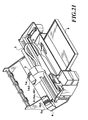
- Figs. 17B, 17C, 17D, and 17E denote four divided images
- Figs. 17F, 17G, 17H, and 17I denote application pattern of the printing ability improving liquid to the above divided images.
- picture elements corresponding to the pattern shown in Fig. 17B are applied with the ink and the printing ability improving liquid.
- the printing head returns to the home position side, and the picture elements corresponding to the pattern shown in Fig. 17C are applied with the ink and the printing ability improving liquid.
- the printing head returns to the home position side, and the printing paper is fed by 32 nozzles.
- the black image is high in density and a sharp image as in Example 1, and a color image can be obtained without bleeding of ink at the boundary between the black image and the color image. Further, water resistant images can be obtained for both the black image and color image.
- the printing method when the print duty exceeds 50% is differed from that of Example 1.
- the printing method when the print duty is less than 50% is the same as in Example 1.
- Figs. 9A to 9C show the printing method at that time, in which with respect to the image data of Fig. 9A, Fig. 9B shows the image (overall black picture elements) printed by the first scanning of the printing head, and Fig. 9C shows the image printed by the second scanning of the printing head. That is, when the print duty exceeds 50%, the image is formed by two scannings.
- Example 1 By the above described printing method, a black image was printed using the same ink and printing ability improving liquid as used in Example 1, and the same effect as Example 1 could be obtained.
- Example 1 as the printing method when the print duty exceeds 50%, application of the printing dot k2 by the printing head 1k2 is made in the forward scanning (printing is made from the home position side) of the printing head, however, alternatively, this may be made in the return scanning (printing is made from the opposite side of the home position) of the printing head.
- Example 2 as the printing method when the print duty exceeds 50%, the second scanning of the printing head is made in forward scanning, however, as described above, this may be made in return scanning. Also in this case, the printing time is reduced as compared with Example 2.
- Example 2 when the print duty exceeds 50%, printing is made according to the pattern shown in Figs. 9B and 9C, however, printing is not specifically limited to this pattern but may be checkered pattern of every picture element as shown in Figs. 4A and 4B.
- Examples 3 and 4 when the print duty is less than 33%, the image is formed by a single scanning of the printing head. However, to improve the reliability even further, printing may be always made by two scannings of the printing heads when the print duty is less than 66%, and printing may be made so that the number of scannings is increased when the duty exceeds 66%.
- the window of the predetermined area is scanned, and the print duty in the window is detected, however, alternatively, the print duty in one scanning width of the printing image may be detected.
- Ink usable for carrying out the present invention should not be limited only to dyestuff ink, and pigment ink having pigment dispersed therein can also be used. Any type of processing liquid can be used, provided that pigment is aggregated with it.
- the following pigment ink can be noted as an example of pigment ink adapted to cause aggregation by mixing with the treatment liquid A1 previously discussed.
- yellow ink Y2, magenta ink M2, cyan ink C2 and black ink K2 each containing pigment and anionic compound can be obtained.
- the following materials are poured in a batch type vertical sand mill (manufactured by Aimex Co.), glass beads each having a diameter of 1 mm is filled as media using anion based high molecular weight material P-1 (aqueous solution containing a solid ingredient of styrene-methacrylic acid-ethylacrylate of 20 % having an acid value of 400 and average molecular weight of 6000, neutralizing agent : potassium hydroxide) as dispersing agent to conduct dispersion treatment for three hours while water-cooling the sand mill. After completion of dispersion, the resultant mixture has a viscosity of 9 cps and pH of 10.0.
- the dispersing liquid is poured in a centrifugal separator to remove coarse particles, and a carbon black dispersing element having a weight-average grain size of 10 nm is produced.
- the final product has a solid ingredient of about 10 %.
- Anionic high molecular P-2 (aqueous solution containing a solid ingredient of 20 % of stylen-acrlylic acid methyl methacrylate having an acid value of 280 and an average molecular weight of 11,000, neutralizing agent : diethanolamine) is used as a dispersing agent and dispersive treatment is conducted in the same manner as production of the black ink K2 whereby yellow color dispersing element having a weight-average grain size of 103 nm is produced.
- the thus obtained yellow dispersing element is sufficiently dispersed in water to obtain yellow ink Y2 for ink jet printing and having pigment contained therein.
- the final product of ink contains a solid ingredient of about 10 %.
- Cyan colored-dispersant element having a weight-average grain size of 120 nm is produced by using the anionic high molecular P-1 used when producing the black ink K2 as dispersing agent, and moreover, using the following materials by conducting dispersing treatment in the same manner as the carbon black dispersing element.
- composition of cyan colored-dispersing element composition of cyan colored-dispersing element
- the thus obtained cyan colored dispersing element is sufficiently stirred to obtain cyan ink C2 for ink jet printing and having pigment contained therein.
- the final product of ink has a solid ingredient of about 9.6 %.
- Magenta color dispersing element having a weight-average grain size of 115 nm is produced by using the anionic high molecular P-1 used when producing the black ink K2 as dispersing agent, and moreover, using the following materials in the same manner as that in the case of the carbon black dispersing agent.
- composition of the magenta colored dispersing element composition of the magenta colored dispersing element
- Magenta ink M2 for ink jet printing and having pigment contained therein is obtained by sufficiently dispersing the magenta colored dispersing element in water.
- the final product of ink has a solid ingredient of about 9.2 %.
- an association body of the above-mentioned dye and low molecule cation type substance or cation type oligomer or coagulated body of the pigment is absorbed by high molecule components included in the processing liquid. Therefore, the coagulated body of the dye or the coagulated body of the pigment caused by association becomes further greater in size to become difficult to penetrate into the gap between the fiber of the printing medium. As a result, only the liquid portion resulting from solid/liquid separation penetrates into the printing paper, both of printing quality and sensibility can be achieved.
- viscosity of the coagulated body formed of the low molecule component of the cation substance or cation type oligomer, anion type dye and cation type substance, or the coagulated body of the pigment is increased to so as not to move according to movement of the liquid medium. Therefore, even when the adjacent ink dots are formed with different colors as in formation of a full color image, the color may not be mixed to each other. Therefore, bleeding is not caused. Also, since the coagulated body is essentially water insoluble, the moisture resistance of the formed image becomes complete. Also, color fastness to light of the formed image can be improved by the shielding effect of the polymer.
- insoluble or coagulate means a function in which a coloring agent, such as the dye and the pigment, is made insoluble or coagulate, and means a phenomenon only in the first stage, for one example, and phenomenon including both of the first and second stages, in another example.
- the kind of the printing medium is not specified in implementation of the present invention, and conventionally used plain paper, such as copy paper, bond paper and so forth can be suitably used.
- plain paper such as copy paper, bond paper and so forth
- a coated paper specially prepared for ink-jet printing, transparent film for OHP and so forth may also be used suitably.
- general wood free paper, glossy paper and so forth may also used suitably.
- the printing ability improving liquid can be ejected in both forward scanning and return scanning of the printing head, high speed operation of the printing apparatus is possible.
- the number of scannings of the printing head can be increased to reduce generation of mist due to rebounding of ink or printing ability improving liquid, thereby improving the reliability.
Applications Claiming Priority (3)
| Application Number | Priority Date | Filing Date | Title |
|---|---|---|---|
| JP20461896 | 1996-08-02 | ||
| JP20461896A JP3313977B2 (ja) | 1996-08-02 | 1996-08-02 | インクジェット記録方法およびインクジェット記録装置 |
| JP204618/96 | 1996-08-02 |
Publications (3)
| Publication Number | Publication Date |
|---|---|
| EP0822087A2 true EP0822087A2 (de) | 1998-02-04 |
| EP0822087A3 EP0822087A3 (de) | 1999-01-13 |
| EP0822087B1 EP0822087B1 (de) | 2003-03-12 |
Family
ID=16493467
Family Applications (1)
| Application Number | Title | Priority Date | Filing Date |
|---|---|---|---|
| EP97305787A Expired - Lifetime EP0822087B1 (de) | 1996-08-02 | 1997-07-31 | Tintenstrahldruckverfahren und Tintenstrahldruckapparat |
Country Status (4)
| Country | Link |
|---|---|
| US (1) | US6137507A (de) |
| EP (1) | EP0822087B1 (de) |
| JP (1) | JP3313977B2 (de) |
| DE (1) | DE69719625T2 (de) |
Cited By (1)
| Publication number | Priority date | Publication date | Assignee | Title |
|---|---|---|---|---|
| US6893103B2 (en) | 2000-10-17 | 2005-05-17 | Seiko Epson Corporation | Ink jet recording apparatus and manufacturing method for functional liquid applied substrate |
Families Citing this family (14)
| Publication number | Priority date | Publication date | Assignee | Title |
|---|---|---|---|---|
| JP3227339B2 (ja) * | 1994-05-23 | 2001-11-12 | キヤノン株式会社 | インクジェット記録装置及びインクジェット記録方法ならびに記録物 |
| US6916092B2 (en) | 1997-08-11 | 2005-07-12 | Canon Kabushiki Kaisha | Recording method |
| JP4036407B2 (ja) * | 1997-12-26 | 2008-01-23 | キヤノン株式会社 | インクジェットプリント装置およびその方法 |
| JP2001018425A (ja) * | 1999-07-05 | 2001-01-23 | Canon Inc | インクジェットプリント方法およびインクジェットプリント装置 |
| US6783209B2 (en) * | 2002-06-03 | 2004-08-31 | Hewlett-Packard Development Company, L.P. | Multiple print bar approach to pen health and fiber management |
| US7083266B2 (en) * | 2002-10-30 | 2006-08-01 | Lexmark International, Inc. | Micro-miniature fluid jetting device |
| JP4958426B2 (ja) * | 2005-11-15 | 2012-06-20 | キヤノンファインテック株式会社 | インクジェット記録方法、記録物および記録装置 |
| US7924459B2 (en) * | 2006-04-11 | 2011-04-12 | Canon Kabushiki Kaisha | Data processing apparatus and method of expanding dot arrangement patterns |
| JP2007296754A (ja) | 2006-04-28 | 2007-11-15 | Canon Inc | インクジェット記録方法およびミスト低減条件設定装置 |
| US20080250971A1 (en) * | 2007-04-16 | 2008-10-16 | Sivapackia Ganapathiappan | Polymer-encapsulated pigment with passivation layer |
| US8210634B2 (en) * | 2010-07-23 | 2012-07-03 | Hewlett-Packard Development Company, L.P. | Image forming apparatus and method thereof |
| JP6323039B2 (ja) * | 2014-02-12 | 2018-05-16 | セイコーエプソン株式会社 | 印刷制御装置、印刷制御方法、および、プログラム |
| JP6593622B2 (ja) * | 2015-03-20 | 2019-10-23 | セイコーエプソン株式会社 | 記録装置 |
| WO2023047770A1 (ja) * | 2021-09-24 | 2023-03-30 | 富士フイルム株式会社 | パターン形成基板製造方法及び液体吐出装置 |
Citations (6)
| Publication number | Priority date | Publication date | Assignee | Title |
|---|---|---|---|---|
| EP0516420A2 (de) * | 1991-05-31 | 1992-12-02 | Canon Kabushiki Kaisha | Farbstrahlaufzeichnungsverfahren und Vorrichtung |
| EP0650840A2 (de) * | 1993-10-28 | 1995-05-03 | Canon Kabushiki Kaisha | Verfahren und Vorrichtung zur Tintenstrahlaufzeichnung |
| EP0703087A2 (de) * | 1994-08-10 | 1996-03-27 | Canon Kabushiki Kaisha | Verfahren und Vorrichtung für Farbstrahldrucker |
| EP0726159A1 (de) * | 1995-02-13 | 1996-08-14 | Canon Kabushiki Kaisha | Verfahren und Vorrichtung für Farbstrahldrucker |
| EP0726158A1 (de) * | 1995-02-13 | 1996-08-14 | Canon Kabushiki Kaisha | Verfahren und Gerät für Tintenstrahldrucken |
| EP0726156A1 (de) * | 1995-02-13 | 1996-08-14 | Canon Kabushiki Kaisha | Tintenstrahldrucker der Tinte und Verarbeitungsflüssigkeit ausstösst zum Drucken |
Family Cites Families (12)
| Publication number | Priority date | Publication date | Assignee | Title |
|---|---|---|---|---|
| JPS5684992A (en) * | 1979-12-15 | 1981-07-10 | Ricoh Co Ltd | Ink jet recording method |
| JP2676699B2 (ja) * | 1987-09-03 | 1997-11-17 | 株式会社リコー | インクジェット記録方法 |
| JP2859296B2 (ja) * | 1989-06-01 | 1999-02-17 | キヤノン株式会社 | 画像再生方法及びその装置 |
| JP2752472B2 (ja) * | 1989-11-02 | 1998-05-18 | キヤノン株式会社 | インクジェット記録装置 |
| JP2861362B2 (ja) * | 1990-10-23 | 1999-02-24 | 富士ゼロックス株式会社 | カラーインクジェットプリンタ |
| ATE235376T1 (de) * | 1991-07-30 | 2003-04-15 | Canon Kk | Vorrichtung und verfahren zum tintenstrahlaufzeichnen |
| EP0587164B1 (de) * | 1992-09-10 | 1998-12-23 | Canon Kabushiki Kaisha | Verfahren und Vorrichtung für Tintenstrahlaufzeichnung |
| JP3152846B2 (ja) * | 1993-09-28 | 2001-04-03 | キヤノン株式会社 | インクジェット記録装置および方法 |
| DE69422483T2 (de) * | 1993-11-30 | 2000-10-12 | Hewlett Packard Co | Farbtintenstrahldruckverfahren und -vorrichtung unter Verwendung eines farblosen Vorläufers |
| JP3029786B2 (ja) * | 1994-09-02 | 2000-04-04 | キヤノン株式会社 | インクジェット記録装置およびテストプリント方法 |
| US5792249A (en) * | 1995-01-25 | 1998-08-11 | Canon Kabushiki Kaisha | Liquid composition, ink set, image-forming method and apparatus using the same |
| JP3313963B2 (ja) * | 1995-02-13 | 2002-08-12 | キヤノン株式会社 | インクジェットプリント方法およびプリント装置 |
-
1996
- 1996-08-02 JP JP20461896A patent/JP3313977B2/ja not_active Expired - Fee Related
-
1997
- 1997-07-31 US US08/904,273 patent/US6137507A/en not_active Expired - Lifetime
- 1997-07-31 DE DE69719625T patent/DE69719625T2/de not_active Expired - Lifetime
- 1997-07-31 EP EP97305787A patent/EP0822087B1/de not_active Expired - Lifetime
Patent Citations (6)
| Publication number | Priority date | Publication date | Assignee | Title |
|---|---|---|---|---|
| EP0516420A2 (de) * | 1991-05-31 | 1992-12-02 | Canon Kabushiki Kaisha | Farbstrahlaufzeichnungsverfahren und Vorrichtung |
| EP0650840A2 (de) * | 1993-10-28 | 1995-05-03 | Canon Kabushiki Kaisha | Verfahren und Vorrichtung zur Tintenstrahlaufzeichnung |
| EP0703087A2 (de) * | 1994-08-10 | 1996-03-27 | Canon Kabushiki Kaisha | Verfahren und Vorrichtung für Farbstrahldrucker |
| EP0726159A1 (de) * | 1995-02-13 | 1996-08-14 | Canon Kabushiki Kaisha | Verfahren und Vorrichtung für Farbstrahldrucker |
| EP0726158A1 (de) * | 1995-02-13 | 1996-08-14 | Canon Kabushiki Kaisha | Verfahren und Gerät für Tintenstrahldrucken |
| EP0726156A1 (de) * | 1995-02-13 | 1996-08-14 | Canon Kabushiki Kaisha | Tintenstrahldrucker der Tinte und Verarbeitungsflüssigkeit ausstösst zum Drucken |
Cited By (1)
| Publication number | Priority date | Publication date | Assignee | Title |
|---|---|---|---|---|
| US6893103B2 (en) | 2000-10-17 | 2005-05-17 | Seiko Epson Corporation | Ink jet recording apparatus and manufacturing method for functional liquid applied substrate |
Also Published As
| Publication number | Publication date |
|---|---|
| US6137507A (en) | 2000-10-24 |
| EP0822087A3 (de) | 1999-01-13 |
| DE69719625T2 (de) | 2003-10-23 |
| JP3313977B2 (ja) | 2002-08-12 |
| JPH1044394A (ja) | 1998-02-17 |
| EP0822087B1 (de) | 2003-03-12 |
| DE69719625D1 (de) | 2003-04-17 |
Similar Documents
| Publication | Publication Date | Title |
|---|---|---|
| EP0596373B1 (de) | Verfahren zur Herstellung eines schwarzen Bildes in dem schwarze Tinte farbiger Tinte überlagert ist | |
| JP3337879B2 (ja) | インクジェットプリント方法およびこれに用いられるインクジェットヘッド、インクジェットカートリッジおよびインクジェットプリント装置 | |
| EP0858899B1 (de) | Tintenstrahldruckgerät und Tintenstrahldruckverfahren | |
| EP0822087B1 (de) | Tintenstrahldruckverfahren und Tintenstrahldruckapparat | |
| JPH07205541A (ja) | カラーインクジェット記録方法 | |
| US6231156B1 (en) | Ink-jet printing apparatus and ejection recovery method of printing head | |
| US6299285B1 (en) | Ink-jet printing apparatus and ink-jet printing method | |
| EP0726148B1 (de) | Tintenstrahldruckapparat und Tintenstrahldruckverfahren zum Durchführen des Druckens durch Ausstossen von Tinte und einer Behandlungsflüssigkeit welche die Tinte unlöslich macht | |
| EP0845356B1 (de) | Tintenstrahldruckvorrichtung zum Drucken mit Tinte und mit einer die Druckfähigkeit verbesserenden Flüssigkeit | |
| US6135656A (en) | Ink-jet printing method and apparatus for performing printing by employing ink and processing liquid making ink insoluble | |
| EP0788885B1 (de) | Tintenstrahldruckgerät und Druckverfahren | |
| US6467892B2 (en) | Ink-jet printing apparatus and ink-jet printing method | |
| JPH1111000A (ja) | インクジェット記録方法およびインクジェット記録装置 | |
| JPH0852868A (ja) | インクジェット記録方法および記録装置 | |
| JPH1148462A (ja) | インクジェット記録方法およびインクジェット記録装置 | |
| JPH10323975A (ja) | インクジェットプリント方法およびインクジェットプリント装置 | |
| JP3576623B2 (ja) | インクジェットプリント方法およびプリント装置 | |
| JPH06136310A (ja) | インクセット、これを用いた黒色画像の形成方法、インクジェット記録方法及びかかるインクを備えたインクジェット記録装置 | |
| JPH08216389A (ja) | インクジェットプリント装置、インクジェットプリント方法およびプリント物 | |
| JPH11138866A (ja) | インクジェット記録方法 | |
| JPH10119320A (ja) | 記録装置および方法および記憶媒体 | |
| JP2000015789A (ja) | インクジェット記録方法およびインクジェット記録装置 | |
| JPH10226088A (ja) | インクジェット記録装置および記録ヘッドの吐出回復処理方法 |
Legal Events
| Date | Code | Title | Description |
|---|---|---|---|
| PUAI | Public reference made under article 153(3) epc to a published international application that has entered the european phase |
Free format text: ORIGINAL CODE: 0009012 |
|
| AK | Designated contracting states |
Kind code of ref document: A2 Designated state(s): DE ES FR GB IT NL |
|
| AX | Request for extension of the european patent |
Free format text: AL;LT;LV;RO;SI |
|
| PUAL | Search report despatched |
Free format text: ORIGINAL CODE: 0009013 |
|
| AK | Designated contracting states |
Kind code of ref document: A3 Designated state(s): AT BE CH DE DK ES FI FR GB GR IE IT LI LU MC NL PT SE |
|
| AX | Request for extension of the european patent |
Free format text: AL;LT;LV;RO;SI |
|
| 17P | Request for examination filed |
Effective date: 19990526 |
|
| AKX | Designation fees paid |
Free format text: DE ES FR GB IT NL |
|
| GRAG | Despatch of communication of intention to grant |
Free format text: ORIGINAL CODE: EPIDOS AGRA |
|
| 17Q | First examination report despatched |
Effective date: 20020314 |
|
| GRAG | Despatch of communication of intention to grant |
Free format text: ORIGINAL CODE: EPIDOS AGRA |
|
| GRAG | Despatch of communication of intention to grant |
Free format text: ORIGINAL CODE: EPIDOS AGRA |
|
| GRAH | Despatch of communication of intention to grant a patent |
Free format text: ORIGINAL CODE: EPIDOS IGRA |
|
| GRAH | Despatch of communication of intention to grant a patent |
Free format text: ORIGINAL CODE: EPIDOS IGRA |
|
| GRAA | (expected) grant |
Free format text: ORIGINAL CODE: 0009210 |
|
| AK | Designated contracting states |
Designated state(s): DE ES FR GB IT NL |
|
| PG25 | Lapsed in a contracting state [announced via postgrant information from national office to epo] |
Ref country code: NL Free format text: LAPSE BECAUSE OF FAILURE TO SUBMIT A TRANSLATION OF THE DESCRIPTION OR TO PAY THE FEE WITHIN THE PRESCRIBED TIME-LIMIT Effective date: 20030312 Ref country code: IT Free format text: LAPSE BECAUSE OF FAILURE TO SUBMIT A TRANSLATION OF THE DESCRIPTION OR TO PAY THE FEE WITHIN THE PRE;WARNING: LAPSES OF ITALIAN PATENTS WITH EFFECTIVE DATE BEFORE 2007 MAY HAVE OCCURRED AT ANY TIME BEFORE 2007. THE CORRECT EFFECTIVE DATE MAY BE DIFFERENT FROM THE ONE RECORDED.SCRIBED TIME-LIMIT Effective date: 20030312 Ref country code: FR Free format text: LAPSE BECAUSE OF FAILURE TO SUBMIT A TRANSLATION OF THE DESCRIPTION OR TO PAY THE FEE WITHIN THE PRESCRIBED TIME-LIMIT Effective date: 20030312 |
|
| REG | Reference to a national code |
Ref country code: GB Ref legal event code: FG4D |
|
| REF | Corresponds to: |
Ref document number: 69719625 Country of ref document: DE Date of ref document: 20030417 Kind code of ref document: P |
|
| NLV1 | Nl: lapsed or annulled due to failure to fulfill the requirements of art. 29p and 29m of the patents act | ||
| PG25 | Lapsed in a contracting state [announced via postgrant information from national office to epo] |
Ref country code: ES Free format text: LAPSE BECAUSE OF FAILURE TO SUBMIT A TRANSLATION OF THE DESCRIPTION OR TO PAY THE FEE WITHIN THE PRESCRIBED TIME-LIMIT Effective date: 20030930 |
|
| PLBE | No opposition filed within time limit |
Free format text: ORIGINAL CODE: 0009261 |
|
| STAA | Information on the status of an ep patent application or granted ep patent |
Free format text: STATUS: NO OPPOSITION FILED WITHIN TIME LIMIT |
|
| EN | Fr: translation not filed | ||
| 26N | No opposition filed |
Effective date: 20031215 |
|
| PGFP | Annual fee paid to national office [announced via postgrant information from national office to epo] |
Ref country code: DE Payment date: 20150731 Year of fee payment: 19 Ref country code: GB Payment date: 20150727 Year of fee payment: 19 |
|
| REG | Reference to a national code |
Ref country code: DE Ref legal event code: R119 Ref document number: 69719625 Country of ref document: DE |
|
| GBPC | Gb: european patent ceased through non-payment of renewal fee |
Effective date: 20160731 |
|
| PG25 | Lapsed in a contracting state [announced via postgrant information from national office to epo] |
Ref country code: DE Free format text: LAPSE BECAUSE OF NON-PAYMENT OF DUE FEES Effective date: 20170201 |
|
| PG25 | Lapsed in a contracting state [announced via postgrant information from national office to epo] |
Ref country code: GB Free format text: LAPSE BECAUSE OF NON-PAYMENT OF DUE FEES Effective date: 20160731 |