EP0820942B1 - Transportkette - Google Patents
Transportkette Download PDFInfo
- Publication number
- EP0820942B1 EP0820942B1 EP97111825A EP97111825A EP0820942B1 EP 0820942 B1 EP0820942 B1 EP 0820942B1 EP 97111825 A EP97111825 A EP 97111825A EP 97111825 A EP97111825 A EP 97111825A EP 0820942 B1 EP0820942 B1 EP 0820942B1
- Authority
- EP
- European Patent Office
- Prior art keywords
- head part
- legs
- conveyor chain
- chain
- connecting pin
- Prior art date
- Legal status (The legal status is an assumption and is not a legal conclusion. Google has not performed a legal analysis and makes no representation as to the accuracy of the status listed.)
- Expired - Lifetime
Links
- 230000003014 reinforcing effect Effects 0.000 claims description 12
- 229910000831 Steel Inorganic materials 0.000 claims description 9
- 239000010959 steel Substances 0.000 claims description 9
- 239000004033 plastic Substances 0.000 claims description 8
- 229920003023 plastic Polymers 0.000 claims description 8
- 239000002184 metal Substances 0.000 claims description 7
- 239000000463 material Substances 0.000 claims description 6
- 230000008878 coupling Effects 0.000 claims description 3
- 238000010168 coupling process Methods 0.000 claims description 3
- 238000005859 coupling reaction Methods 0.000 claims description 3
- OKTJSMMVPCPJKN-UHFFFAOYSA-N Carbon Chemical compound [C] OKTJSMMVPCPJKN-UHFFFAOYSA-N 0.000 claims 1
- 229910052799 carbon Inorganic materials 0.000 claims 1
- 230000002787 reinforcement Effects 0.000 description 8
- 206010038743 Restlessness Diseases 0.000 description 2
- 239000004918 carbon fiber reinforced polymer Substances 0.000 description 2
- 229920002430 Fibre-reinforced plastic Polymers 0.000 description 1
- 230000000694 effects Effects 0.000 description 1
- 239000011151 fibre-reinforced plastic Substances 0.000 description 1
- 239000007769 metal material Substances 0.000 description 1
Images

Classifications
-
- B—PERFORMING OPERATIONS; TRANSPORTING
- B65—CONVEYING; PACKING; STORING; HANDLING THIN OR FILAMENTARY MATERIAL
- B65G—TRANSPORT OR STORAGE DEVICES, e.g. CONVEYORS FOR LOADING OR TIPPING, SHOP CONVEYOR SYSTEMS OR PNEUMATIC TUBE CONVEYORS
- B65G17/00—Conveyors having an endless traction element, e.g. a chain, transmitting movement to a continuous or substantially-continuous load-carrying surface or to a series of individual load-carriers; Endless-chain conveyors in which the chains form the load-carrying surface
- B65G17/06—Conveyors having an endless traction element, e.g. a chain, transmitting movement to a continuous or substantially-continuous load-carrying surface or to a series of individual load-carriers; Endless-chain conveyors in which the chains form the load-carrying surface having a load-carrying surface formed by a series of interconnected, e.g. longitudinal, links, plates, or platforms
- B65G17/08—Conveyors having an endless traction element, e.g. a chain, transmitting movement to a continuous or substantially-continuous load-carrying surface or to a series of individual load-carriers; Endless-chain conveyors in which the chains form the load-carrying surface having a load-carrying surface formed by a series of interconnected, e.g. longitudinal, links, plates, or platforms the surface being formed by the traction element
- B65G17/086—Conveyors having an endless traction element, e.g. a chain, transmitting movement to a continuous or substantially-continuous load-carrying surface or to a series of individual load-carriers; Endless-chain conveyors in which the chains form the load-carrying surface having a load-carrying surface formed by a series of interconnected, e.g. longitudinal, links, plates, or platforms the surface being formed by the traction element specially adapted to follow a curved path
-
- B—PERFORMING OPERATIONS; TRANSPORTING
- B65—CONVEYING; PACKING; STORING; HANDLING THIN OR FILAMENTARY MATERIAL
- B65G—TRANSPORT OR STORAGE DEVICES, e.g. CONVEYORS FOR LOADING OR TIPPING, SHOP CONVEYOR SYSTEMS OR PNEUMATIC TUBE CONVEYORS
- B65G2201/00—Indexing codes relating to handling devices, e.g. conveyors, characterised by the type of product or load being conveyed or handled
- B65G2201/02—Articles
Definitions
- the invention relates to a transport chain for a conveyor system, in which each one Plastic-made chain link a plate carrying the material to be conveyed, one with a cylindrical bore provided head part and a extending, has a fork-shaped section with two legs, at the cardan joint Coupling of two chain links into the cylindrical bore of the head part rotatably inserted bolt with a transverse bore and the legs of the in the running direction provide chain links in front of it with aligned holes are, and that in the transverse bore and in the bores of the legs a metallic Connection pin is inserted.
- Such a transport chain is known from DE 32 35 224 C2.
- the plates carrying the material to be conveyed are on top.
- On the in the direction of transport They are toothed at the front and rear transverse edges, the teeth being offset to each other, so that the teeth of the rear transverse edge into the tooth gaps of the engage the front transverse edge of the subsequent chain link.
- the advantage of such Transport chains is that they are both in a horizontal plane as well can be deflected around a horizontal axis. The redirection in a horizontal The bolt inserted into the hole in the head section enables level. The Redirection around a horizontal axis enables the coupling of the chain links Connecting pin.
- the plates form with the head part and the fork-shaped section is a one-piece molded part, which is made of plastic is. Due to the elasticity, this leads to a relatively strong elongation of the Transport chain. This stretch causes unfavorable dynamic behavior, so that there is a restless run, in the industry as a so-called stick-slip effect referred to as. In addition, there is a not exactly definable Drive situation.
- the restless run affects the location of the material to be conveyed and thus negatively affect the functional safety of the conveyor system.
- the drive of the Transport chain is usually done by sprockets, over which the transport chain to be led. These sprockets engage the connecting pin. Arise by the non-rotatable storage unfavorable engagement conditions, so that it too increased wear on the chain wheel and the transport chain. Thereby operational safety and the lifespan of the transport chain are reduced.
- the invention has for its object a transport chain closer to the beginning type described in a structurally simple manner so that the stretch reduced compared to the known designs, extended life and during this time, a constant, defined drive situation is guaranteed becomes.
- the task is solved by the inserted in the bore of the head part Bolt has a recess in which a rotatably mounted on the connecting pin meshing with the teeth of a drive wheel, made of one material with a roller manufactured with higher strength than the plastic of the head part lies, and / or that the mutually facing sides of the legs of the fork-shaped Section a reinforcing insert is arranged.
- a drive situation is created by the metal sleeve rotatably mounted on the connecting pin created that is comparable to that of steel roller chains. This will especially the friction is reduced, so that the life of the drive wheel and the chain link is increased.
- the role can be dispensed with and the transport chain with the reinforcing inserts be equipped.
- the combination of the role with the reinforcement insert is also advantageous.
- This reinforcement insert increases the rigidity of the chain. she is in the assembly of the transport chain by the connecting pin in the legs of the respective chain link fixed.
- the inventive design of the Transport chain are particularly when combining the role with the reinforcement insert the attacking tensile forces of heavy-duty parts, such as the roller, the connecting pin and the reinforcing insert.
- the relatively small Managers and the lifting of the load are carried away by the plastic parts.
- the gimbal mobility remains of the chain fully preserved.
- the reinforcing insert consists of a V-shaped, the contour of the inner surface of the legs of the fork-shaped section appropriately shaped reinforcing tape, which is preferably is made of metal, and which with holes for fixing by means of the connecting pin is provided.
- the holes are in the free end areas of the two Ridges of the reinforcement insert.
- the reinforcement band grips around for further fixation the cylindrical bolt so that this area of the reinforcement tape runs in an arc. Through the reinforcement band are connected the forces, preferably made of steel and the connecting pin transmitted through extremely heavy-duty components.
- the reinforcing tape is made of a fiber-reinforced, for example, a carbon fiber reinforced plastic. Such materials have a low stretch.
- the weight is relatively light.
- the reinforcement insert can also be made of metal, preferably steel become. The same applies to the role. Metallic materials offer a sufficient Strength and can also be edited very well. According to one Another proposal is that the roller is made of a sintered metal becomes. This results very much due to the self-lubricating properties good emergency running conditions.
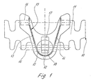
- the chain link 10 shown in FIG. 1 consists of a plate 11 on which the Conveyed goods, not shown, rests on the lower one, facing away from the conveyed goods Side arranged head part 12 and two extending from the head part 12 Legs 13, 14, the mutual distances between them from the head part 12 get bigger.
- the head part 12 lies, seen in the transport direction of the transport chain, at the front of the chain link.
- the head part 12 has a cylindrical, transverse provided to the plane of the plate 11 standing hole in which a cylindrical bolt 15 is rotatably used. This bolt 15 is provided with a transverse bore, in a connecting pin 16 made of steel is rotatably inserted. This will make the connection created with the chain link 10 lying in front in the transport direction.
- the two legs 13, 14 of the fork-shaped section of the chain link 10 also with two holes aligned with the transverse bore of the bolt 15 provided, through which the connecting pin 16 is guided. Also in the head part 12 opposite area, the two legs 13, 14 are provided with bores, so that the chain link behind in the transport direction with the one shown in Fig. 1 can be connected.
- the cylindrical bolt 15 is with a recess 17 provided so that a roller 18 rotatably placed on the connecting pin 16 can be.
- the roller 18 of each chain link 10 comes with those not shown Drive chain wheels of the transport chain are engaged. This creates relationships created like a roller chain made of steel.
- the plate 11, the headboard 12 and the legs 13, 14 of the fork-shaped section are made of plastic.
- each chain link is for transmitting the forces 10 reinforced with an insert 19, which in the illustrated embodiment consists of a Steel band or a fiber-reinforced plastic is formed, which on the inner, facing sides of the legs 13, 14 and the bolt 15th embraces.
- the band 19 is provided with appropriate holes to the respective Pass connecting pin 16 through which the band is also fixed.
- each chain link 10 with respect to the straight central longitudinal axis of a chain strand rotated left and right through an angle of, for example, 10 degrees become.
- the chain links 10 are on the front and rear in the transport direction Crossed teeth, in such a way that the teeth of the rear transverse edge in the Engage tooth gaps in the front transverse edge of the subsequent chain link. This will u. a. also avoided a gap between two chain links 10, so that from a technical functional point of view the support surface formed from the chain links 10 is to be regarded as a full area.
- the reinforcing band 19 can be made of steel or a fiber-reinforced one Plastic molded. Preferably comes a carbon fiber reinforced plastic into consideration.
- the roller 18 can be made of steel or a sintered metal become.
Landscapes
- Engineering & Computer Science (AREA)
- Mechanical Engineering (AREA)
- Chain Conveyers (AREA)
- Iron Core Of Rotating Electric Machines (AREA)
- Dry Shavers And Clippers (AREA)
Description
- Figur 1
- ein Kettenglied als Einzelteil der erfindungsgemäßen Transportkette in einer Unteransicht,
- Figur 2
- mehrere miteinander gekoppelte Kettenglieder gemäß der Figur 1, ebenfalls in einer Unteransicht und
- Figur 3
- die Kettenglieder gemäß der Figur 2 in einer Draufsicht.
Claims (5)
- Transportkette für eine Förderanlage, bei der jedes aus einem Kunststoff gefertigte Kettenglied (10) eine das Fördergut tragende Platte (11), ein mit einer zylindrischen Bohrung versehenes Kopfteil (12) und einen davon sich erstreckenden, gabelförmigen Abschnitt mit zwei Schenkeln (13, 14) aufweist, bei der zur kardangelenkigen Koppelung von zwei Kettengliedern (10) ein in die zylindrische Bohrung des Kopfteils (12) drehbar eingesetzter Bolzen (15) mit einer Querbohrung und die Schenkel (13, 14) des in Laufrichtung davorliegenden Kettengliedes mit dazu fluchtenden Bohrungen versehen sind, und daß in die Bohrungen der Kopfteile (12) und in die Bohrungen der Schenkel (13, 14) ein metallischer Verbindungsstift (15) eingesetzt ist, dadurch gekennzeichnet, daß der in die Bohrung des Kopfteils (12) eingesetzte Bolzen (15) eine Aussparung (17) aufweist, in der eine auf dem Verbindungsstift (16) drehbar gelagerte, mit den Zähnen eines Antriebsrades in Eingriff stehende, aus einem Werkstoff mit gegenüber dem Kunststoff des Kopfteils (12) höherer Festigkeit gefertigte Rolle (18) liegt, und/oder daß an den einander zugewandten Seiten der Schenkel (13, 14) des gabelförmigen Abschnittes eine Verstärkungseinlage (19) angeordnet ist.
- Transportkette nach Anspruch 1, dadurch gekennzeichnet, daß die Verstärkungseinlage (19) aus einem V-förmig, der Kontur der Innenflächen der Schenkel (13, 14) des gabelförmigen Abschnittes entsprechend geformten Verstärkungsband besteht, welches mit Bohrungen zur Fixierung mittels des Verbindungsstiftes (16) versehen ist.
- Transportkette nach Anspruch 2, dadurch gekennzeichnet, daß die Rolle (18) und die Verstärkungseinlage (19) aus Stahl gefertigt sind.
- Transportkette nach Anspruch 1, dadurch gekennzeichnet, daß die Verstärkungseinlage (19) aus einem faserverstärkten, vorzugsweise kohlefaserverstärkten Kunststoff besteht.
- Transportkette nach Anspruch 1, dadurch gekennzeichnet, daß die Rolle (18) aus einem Sintermetall besteht.
Applications Claiming Priority (2)
| Application Number | Priority Date | Filing Date | Title |
|---|---|---|---|
| DE29612735U DE29612735U1 (de) | 1996-07-23 | 1996-07-23 | Transportkette |
| DE29612735U | 1996-07-23 |
Publications (2)
| Publication Number | Publication Date |
|---|---|
| EP0820942A1 EP0820942A1 (de) | 1998-01-28 |
| EP0820942B1 true EP0820942B1 (de) | 2000-05-24 |
Family
ID=8026840
Family Applications (1)
| Application Number | Title | Priority Date | Filing Date |
|---|---|---|---|
| EP97111825A Expired - Lifetime EP0820942B1 (de) | 1996-07-23 | 1997-07-11 | Transportkette |
Country Status (3)
| Country | Link |
|---|---|
| US (1) | US6079552A (de) |
| EP (1) | EP0820942B1 (de) |
| DE (2) | DE29612735U1 (de) |
Families Citing this family (14)
| Publication number | Priority date | Publication date | Assignee | Title |
|---|---|---|---|---|
| US6161685A (en) * | 1999-03-26 | 2000-12-19 | Rexnord Corporation | Thermoplastic chain link for a modular conveyor chain |
| US6364095B1 (en) * | 2000-04-13 | 2002-04-02 | Span Tech Llc | Modular conveyor system with side flexing belt having roller support |
| DE10040081A1 (de) * | 2000-08-16 | 2002-03-07 | Bosch Gmbh Robert | Kettenglied, insbesondere einer kurvengängigen Förderkette |
| DE102006004807A1 (de) * | 2006-01-24 | 2007-08-02 | Hauni Maschinenbau Ag | Förderkette als kurvengängige und laufrollenfreie Tragförderkette |
| ATE401269T1 (de) * | 2006-04-25 | 2008-08-15 | Ewab Holding Ag | Förderkette |
| US7681718B2 (en) * | 2006-12-15 | 2010-03-23 | Rexnord Industries, Llc | Modular belt link having a detachably fixed reinforcement link |
| DE102010024865B4 (de) * | 2010-06-24 | 2014-02-27 | Technische Universität Chemnitz | Kunststoff-Kettenglied, Verfahren zur Herstellung eines Kunststoff-Kettengliedes, Endloskette mit zumindest einem Kunststoff-Kettenglied und Endloskette mit einer Mehrzahl von Kunststoff-Kettengliedern |
| MY172945A (en) * | 2011-05-10 | 2019-12-16 | Flexmove System M Sdn Bhd | A link for a conveyor chain, a conveyor chain made up of said links and a method of operation of said conveyor chain |
| DE102011112396A1 (de) | 2011-09-03 | 2013-03-07 | Robert Bosch Gmbh | Kettenglied mit durch Gleitabschnitt getrennten Gelenk- und Gabelabschnitt |
| ITBO20120093A1 (it) * | 2012-02-28 | 2013-08-29 | Bett Sistemi Srl | Convogliatore a maglie asimmetriche e corrispondente maglia asimmetrica. |
| US8985318B2 (en) | 2012-05-15 | 2015-03-24 | Ashworth Bros., Inc. | Conveyor belt with composite link |
| WO2014066556A1 (en) | 2012-10-25 | 2014-05-01 | Solus Industrial Innovations, Llc | Device and method for controlling the wear of the rail of a conveyor |
| EP2925643A4 (de) | 2012-11-29 | 2017-01-04 | Regal Beloit America, Inc. | Förderer mit seitlicher biegung |
| EP3105153B1 (de) * | 2014-02-14 | 2019-09-25 | BETT SISTEMI s.r.l. | Förderer zum transport von produkten |
Family Cites Families (5)
| Publication number | Priority date | Publication date | Assignee | Title |
|---|---|---|---|---|
| US4004682A (en) * | 1975-08-14 | 1977-01-25 | Adamation, Inc. | Type S chain |
| NL7708946A (nl) * | 1977-08-12 | 1979-02-14 | Transportsystemen Conveyor Sys | Transportketting bestaande uit schalmen van kunststof. |
| SE455861B (sv) * | 1981-09-30 | 1988-08-15 | Skf Ab | Anordning vid en kedjetransportor |
| IT8134921V0 (it) * | 1981-12-22 | 1981-12-22 | Marbett S N C Di Mariani Betta | Catena di trasporto con rivestimento antiusura |
| SE460355B (sv) * | 1988-01-08 | 1989-10-02 | Mats Ejvin Wahren | Transportkedja |
-
1996
- 1996-07-23 DE DE29612735U patent/DE29612735U1/de not_active Expired - Lifetime
-
1997
- 1997-07-11 DE DE59701746T patent/DE59701746D1/de not_active Expired - Fee Related
- 1997-07-11 EP EP97111825A patent/EP0820942B1/de not_active Expired - Lifetime
- 1997-07-16 US US08/895,007 patent/US6079552A/en not_active Expired - Fee Related
Also Published As
| Publication number | Publication date |
|---|---|
| DE59701746D1 (de) | 2000-06-29 |
| US6079552A (en) | 2000-06-27 |
| DE29612735U1 (de) | 1996-09-12 |
| EP0820942A1 (de) | 1998-01-28 |
Similar Documents
| Publication | Publication Date | Title |
|---|---|---|
| EP0820942B1 (de) | Transportkette | |
| DE3235224C2 (de) | ||
| DE69716660T2 (de) | Einrichtung zum Führen eines Teleskopteils für einen Teleskopausleger | |
| DE69822854T2 (de) | Kettenfördersystem | |
| DE3137894A1 (de) | Fuehrungsschiene fuer eine kettensaege | |
| EP2750993B1 (de) | Kettenglied mit durch gleitabschnitt getrennten gelenk- und gabelabschnitt | |
| EP0459104B1 (de) | Flyerkette | |
| DE2830251A1 (de) | Kette fuer kreisfoerderer | |
| DE102013107866B4 (de) | Gabellaschenkette | |
| EP0099481B1 (de) | Trogförderkette | |
| DE1605570B2 (de) | Fahrzeug-gleiskette | |
| EP0367755B1 (de) | Mitnehmeranordnung | |
| EP0120996B1 (de) | Fördervorrichtung | |
| DE60108638T2 (de) | Ablenkvorrichtung für förderer | |
| EP0473953B1 (de) | Gurtförderer | |
| EP1849723B1 (de) | Förderkette | |
| DE3125111C2 (de) | Gelenkkette für Stetigförderer | |
| DE19610935A1 (de) | Pfeilgliederkette | |
| DE3502946C2 (de) | Kettenförderer | |
| EP1120367B1 (de) | Staurollenförderkette | |
| DE10112597B4 (de) | Rohrkettenförderer für Transport oder Dosieren von insbesondere Schüttgut | |
| DE19832637C2 (de) | Raupenfahrwerk | |
| DE3802914C2 (de) | ||
| AT403158B (de) | Förderkette | |
| DE102008060587B4 (de) | Förderband |
Legal Events
| Date | Code | Title | Description |
|---|---|---|---|
| PUAI | Public reference made under article 153(3) epc to a published international application that has entered the european phase |
Free format text: ORIGINAL CODE: 0009012 |
|
| 17P | Request for examination filed |
Effective date: 19971202 |
|
| AK | Designated contracting states |
Kind code of ref document: A1 Designated state(s): CH DE FR GB IT LI SE |
|
| AX | Request for extension of the european patent |
Free format text: AL;LT;LV;RO;SI |
|
| RBV | Designated contracting states (corrected) |
Designated state(s): CH DE FR GB IT LI SE |
|
| RTI1 | Title (correction) |
Free format text: CONVEYOR CHAIN |
|
| GRAG | Despatch of communication of intention to grant |
Free format text: ORIGINAL CODE: EPIDOS AGRA |
|
| 17Q | First examination report despatched |
Effective date: 19990809 |
|
| GRAG | Despatch of communication of intention to grant |
Free format text: ORIGINAL CODE: EPIDOS AGRA |
|
| GRAH | Despatch of communication of intention to grant a patent |
Free format text: ORIGINAL CODE: EPIDOS IGRA |
|
| GRAH | Despatch of communication of intention to grant a patent |
Free format text: ORIGINAL CODE: EPIDOS IGRA |
|
| GRAA | (expected) grant |
Free format text: ORIGINAL CODE: 0009210 |
|
| AK | Designated contracting states |
Kind code of ref document: B1 Designated state(s): CH DE FR GB IT LI SE |
|
| REG | Reference to a national code |
Ref country code: CH Ref legal event code: NV Representative=s name: ISLER & PEDRAZZINI AG Ref country code: CH Ref legal event code: EP |
|
| GBT | Gb: translation of ep patent filed (gb section 77(6)(a)/1977) |
Effective date: 20000517 |
|
| ITF | It: translation for a ep patent filed | ||
| REF | Corresponds to: |
Ref document number: 59701746 Country of ref document: DE Date of ref document: 20000629 |
|
| ET | Fr: translation filed | ||
| PLBE | No opposition filed within time limit |
Free format text: ORIGINAL CODE: 0009261 |
|
| STAA | Information on the status of an ep patent application or granted ep patent |
Free format text: STATUS: NO OPPOSITION FILED WITHIN TIME LIMIT |
|
| 26N | No opposition filed | ||
| REG | Reference to a national code |
Ref country code: GB Ref legal event code: IF02 |
|
| PGFP | Annual fee paid to national office [announced via postgrant information from national office to epo] |
Ref country code: FR Payment date: 20030630 Year of fee payment: 7 |
|
| PGFP | Annual fee paid to national office [announced via postgrant information from national office to epo] |
Ref country code: GB Payment date: 20030709 Year of fee payment: 7 |
|
| PGFP | Annual fee paid to national office [announced via postgrant information from national office to epo] |
Ref country code: SE Payment date: 20030714 Year of fee payment: 7 |
|
| PGFP | Annual fee paid to national office [announced via postgrant information from national office to epo] |
Ref country code: CH Payment date: 20030724 Year of fee payment: 7 |
|
| PG25 | Lapsed in a contracting state [announced via postgrant information from national office to epo] |
Ref country code: GB Free format text: LAPSE BECAUSE OF NON-PAYMENT OF DUE FEES Effective date: 20040711 |
|
| PG25 | Lapsed in a contracting state [announced via postgrant information from national office to epo] |
Ref country code: SE Free format text: LAPSE BECAUSE OF NON-PAYMENT OF DUE FEES Effective date: 20040712 |
|
| PG25 | Lapsed in a contracting state [announced via postgrant information from national office to epo] |
Ref country code: LI Free format text: LAPSE BECAUSE OF NON-PAYMENT OF DUE FEES Effective date: 20040731 Ref country code: CH Free format text: LAPSE BECAUSE OF NON-PAYMENT OF DUE FEES Effective date: 20040731 |
|
| EUG | Se: european patent has lapsed | ||
| GBPC | Gb: european patent ceased through non-payment of renewal fee |
Effective date: 20040711 |
|
| REG | Reference to a national code |
Ref country code: CH Ref legal event code: PL |
|
| PG25 | Lapsed in a contracting state [announced via postgrant information from national office to epo] |
Ref country code: FR Free format text: LAPSE BECAUSE OF NON-PAYMENT OF DUE FEES Effective date: 20050331 |
|
| REG | Reference to a national code |
Ref country code: FR Ref legal event code: ST |
|
| PG25 | Lapsed in a contracting state [announced via postgrant information from national office to epo] |
Ref country code: IT Free format text: LAPSE BECAUSE OF NON-PAYMENT OF DUE FEES;WARNING: LAPSES OF ITALIAN PATENTS WITH EFFECTIVE DATE BEFORE 2007 MAY HAVE OCCURRED AT ANY TIME BEFORE 2007. THE CORRECT EFFECTIVE DATE MAY BE DIFFERENT FROM THE ONE RECORDED. Effective date: 20050711 |
|
| PGFP | Annual fee paid to national office [announced via postgrant information from national office to epo] |
Ref country code: DE Payment date: 20071217 Year of fee payment: 11 |
|
| PG25 | Lapsed in a contracting state [announced via postgrant information from national office to epo] |
Ref country code: DE Free format text: LAPSE BECAUSE OF NON-PAYMENT OF DUE FEES Effective date: 20090203 |