EP0819922A2 - Protection de chocs pour un dispositif de mesure de force - Google Patents
Protection de chocs pour un dispositif de mesure de force Download PDFInfo
- Publication number
- EP0819922A2 EP0819922A2 EP97110270A EP97110270A EP0819922A2 EP 0819922 A2 EP0819922 A2 EP 0819922A2 EP 97110270 A EP97110270 A EP 97110270A EP 97110270 A EP97110270 A EP 97110270A EP 0819922 A2 EP0819922 A2 EP 0819922A2
- Authority
- EP
- European Patent Office
- Prior art keywords
- bore
- shock protection
- section
- diameter
- bolt
- Prior art date
- Legal status (The legal status is an assumption and is not a legal conclusion. Google has not performed a legal analysis and makes no representation as to the accuracy of the status listed.)
- Granted
Links
Images


Classifications
-
- G—PHYSICS
- G01—MEASURING; TESTING
- G01L—MEASURING FORCE, STRESS, TORQUE, WORK, MECHANICAL POWER, MECHANICAL EFFICIENCY, OR FLUID PRESSURE
- G01L1/00—Measuring force or stress, in general
- G01L1/26—Auxiliary measures taken, or devices used, in connection with the measurement of force, e.g. for preventing influence of transverse components of force, for preventing overload
-
- G—PHYSICS
- G01—MEASURING; TESTING
- G01G—WEIGHING
- G01G23/00—Auxiliary devices for weighing apparatus
- G01G23/005—Means for preventing overload
-
- G—PHYSICS
- G01—MEASURING; TESTING
- G01L—MEASURING FORCE, STRESS, TORQUE, WORK, MECHANICAL POWER, MECHANICAL EFFICIENCY, OR FLUID PRESSURE
- G01L1/00—Measuring force or stress, in general
- G01L1/20—Measuring force or stress, in general by measuring variations in ohmic resistance of solid materials or of electrically-conductive fluids; by making use of electrokinetic cells, i.e. liquid-containing cells wherein an electrical potential is produced or varied upon the application of stress
- G01L1/22—Measuring force or stress, in general by measuring variations in ohmic resistance of solid materials or of electrically-conductive fluids; by making use of electrokinetic cells, i.e. liquid-containing cells wherein an electrical potential is produced or varied upon the application of stress using resistance strain gauges
- G01L1/2206—Special supports with preselected places to mount the resistance strain gauges; Mounting of supports
- G01L1/2243—Special supports with preselected places to mount the resistance strain gauges; Mounting of supports the supports being parallelogram-shaped
Definitions
- the invention relates to a shock protection for a force measuring device, in particular for a balance, comprising a block of material with a fixed parallelogram leg, one for holding the one to be measured Power-serving, deflectable parallelogram leg, two in the Bending-elastic parallelogram plane, the two parallelogram legs connecting links and at least one lever that with a coupling the deflectable parallelogram leg is connected.
- Overload protection devices for scales are known. These serve usually to prevent damage to the measuring cell if an excessive load is placed on the weighing pan or if the load due to careless handling falls vertically onto the weighing pan.
- the Most known overload protection devices are designed as stops trained, which limit the vertical path of the load receiver, so none in the measuring cell beyond the calculated forces can be initiated. These devices generally have one very simple structure and do their job flawlessly.
- Scales can be damaged not only when weighing, but also on the transport from the manufacturer to the buyer and possibly also at the Transport and cleaning within the premises of the User.
- forces that damage the scale do not occur exclusively on the force measuring device in the vertical direction, but also from all possible directions inclined to the vertical.
- scales become more complex and consequently also more expensive Packaged in shock-absorbing materials.
- Such packaging is very voluminous and therefore require, especially for worldwide shipping, a large and therefore expensive transport volume. Still, they only offer limited protection.
- the parallelogram legs, the handlebars and the paddock is often made from a one-piece block of material.
- the Bends that connect the individual elements with each other a thickness that is only a few hundredths of a millimeter to a few Amount to tenths of a millimeter. Protecting these precise elements against The impact of shock is therefore extremely important.
- the object of the invention is to provide shock protection for the Force measuring device, which the bending points within the Block of material not only during transport, but also permanently during use and handling of the scale before the effects of Protects against blows.
- shock protection for one Force measuring device in particular for a balance, comprising a Block of material with a fixed parallelogram leg, one for Inclusion of the deflectable force to be measured Parallelogram legs, two flexible in the parallelogram plane, the two parallelogram arms connecting links and at least a lever that is coupled to the deflectable Parallelogram leg is connected, with a locking bolt in a the force measuring device at least partially penetrating bore used and on one of the parts of the force measuring device Material blocks is connected without play and with respect to the rest penetrated parts has a radial play.
- the permanent shock protection protects the force measuring device not only during transportation and use, but it can are already installed in the factory before the scales check the quality and Final checks and the adjustment goes through.
- the shock protection can always stay deployed; preparing the scale for transport and corresponding measures for commissioning later are not necessary. This means that there is no need to interfere with the mechanics of the scale untrained people.
- the shock protection can be used on force measuring devices with one or more Levers are used. It can be done with a single locking bolt work that penetrates several levers, or several can Safety bolts are used, which each have individual levers and / or Penetrate the learner and protect the corresponding bending points.
- A can also be used to axially determine the position of the safety bolt
- Cross bolts may be provided.
- the generation of the for the storage of the Safety bolt and the cross bolt necessary holes is very simply because their diameter is along the entire length of the holes is constant. In the simplest embodiment of the invention, the completely penetrate the material block in both holes. Also to the Accuracy of the distances between the axes of the two holes relatively low demands.
- the cross bolt can either be pressed or glued into the cross hole. Of the The safety pin is inserted into the hole provided by hand inserted and then with a torque wrench by approx. 45 ° - 90 ° turned. Another security measure or subsequent Setting measurements are not necessary. Even the manufacture of the two Bolting is easy; the cross bolt is along its entire length cylindrical; the locking pin consists of a turned part, with a End area is flattened by a partial milling.
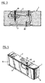
- Only one piece of material block 1 is of a scale in FIG. 1 shown in which a parallel guidance through material-free areas is trained.
- the material-free areas are due to spark erosion generated and form the boundary lines between the elements of the Parallelogram guidance.
- the reference numerals 2 and 3 are parallel to top surface and the bottom surface of the cuboid Material block 1 denotes an upper and a lower link.
- the two Handlebars 2 and 3 are by bending points 6, 7, 8 and 9 with the Parallelogram legs 10 and 11 connected.
- the parallelogram leg 10 is fixed, the parallelogram leg 11 is from the learners 2, 3 guided in parallel deflectable.
- the material thickness in the Areas of the bending points 6-9 are in the range of a few Tenths of a millimeter.
- the material-free area 4 and a further material-free area 19 form a first lever 18 within the material block 1. This is on the right through a coupling 17 with the deflectable Parallelogram leg 11 connected. On the other hand, he's under Interposition of a bending point 20 with a second lever 25 connected. The second lever 25 is through a bending point 26 with the fixed parallelogram leg 10 connected.
- the geometrical Shape of the two levers 18 and 25 and the arrangement of the levers and Handlebars or parallelogram legs connecting bending points determined by the requirements placed on the measuring cell. Alternatively, more or fewer than two levers in the material block 1 be trained.
- the bore 61 has a diameter D 1 in the upper link 2, in the first lever 18, in the second lever 25 and at least in a section of part 63 of the parallelogram leg 10. Stepped bores with different diameters could also be provided in the individual elements of the material block.
- a threaded section 67 In the end region of the bore 61 there is a threaded section 67, which merges below into a cylindrical bore 71 of smaller diameter D 2 .
- the two coaxial bores 61 and 71 have narrow dimensional tolerances.
- the bore 71 can end in a conical section 69, which serves to center the securing bolt 65. In this case, no close tolerance in the bore 71 is necessary.
- a screw head 73 is located on the top of the securing bolt 65.
- the shaft 75 of the securing bolt 65 has a diameter D 3 which is substantially smaller than the diameter D 1 of the bore 61.
- the lower end 77 of the securing bolt 65 which is located in the narrower bore section 71 , is threadless and has a diameter that is only slightly smaller than the bore 71.
- a thread 79 is formed in the shaft 75, which corresponds to the threaded bore 67.
- the lower end 81 of the shaft 75 is bevelled or rounded.
- a first circumferential shoulder 83 is formed on the shaft 75, the outer diameter D 4 of which is smaller than the diameter D 1 of the bore 61.
- the play of the first shoulder 83 in the bore 61 is very small and is in the range of for example 0.1mm.
- a second circumferential shoulder 85 is formed in the area of the penetration of the upper link 2.
- the diameter D 5 of the shoulder 85 is also smaller than the diameter D 1 of the bore 61, but the difference in diameter is larger than that of the shoulder 83 in the region of the second lever 25.
- the two parallelogram legs 10, 11 and the two links 2, 3 can also be manufactured as separate parts, into which the levers 18, 25 and their connections are inserted.
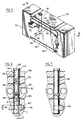
- a bore 161 is made in the area of the material block 101 in which the two links 102 and 103 and the two levers 118 and 125 lie one above the other, which extends vertically from the upper surface of the material block 101 this extends into the fixed parallelogram leg 110, ie into the section 163 of the parallelogram leg 110 projecting between the two links 102 and 103.
- a securing bolt 165 In the bore 161 there is a securing bolt 165, the design and function of which will be explained in more detail with reference to FIGS. 6 to 11.
- the bore 161 has a diameter D 1 in the upper link 102, in the first lever 118, in the second lever 125 and at least in a section of part 163 of the parallelogram leg 110.
- the bore 161 can extend through the entire material block 101 and always have the same diameter D 1 .
- the bore 161, which consists of coaxially lying sections, is produced with narrow dimensional tolerances.
- a transverse bore 162 is formed which is perpendicular to the bore 161 and which can extend through the parallelogram leg 110.
- the cross bore 162 serves to receive a cylindrical cross pin 164, at one end of which a head 166 can be formed.
- the diameter of the cross pin 164 is either such that it is stuck in the cross bore 162 after it has been pushed in, or it is glued into the cross bore 162.
- the transverse bore 162 penetrates the bore 161, the overlap X being on the order of approximately 20 to 30 percent of D 1 .
- the cylindrical shaft 175 of the securing bolt 165 comprises four sections adjoining the head 173.
- the first cylindrical section 170 carries at least one circumferential shoulder 183.
- the second section 172 is likewise cylindrical, but with a larger diameter D 5
- the third section 174 has a circular or elliptical cross section, the center or axis B of which is offset to the axis A of the locking bolt 165.
- the fourth section 176 forming the end is also cylindrical, but a flattening 178 with a section height h which is parallel to the axis A is attached at least at one point.
- the height h of the cylinder section cut off by the flattening 178 corresponds at least to the amount of the overlap X.
- the third section 174 lies in the area of the overlap X.
- the flattening 178 also extends over the third section 174, if the elliptical cross section or the circular cross section, its Axis B is offset from axis A, radially over the flattening in the fourth Section 176 would protrude.
- the first circumferential shoulder 183 formed on the shaft 175 of the securing bolt 165, the outside diameter D 4 of which is smaller than the diameter D 1 of the bore 161.
- the play of the first shoulder 183 in the bore 161 is very small and lies in the range of 0.1 mm, for example.
- a second shoulder 187 may be used with play to bore 161 in the area of penetration of bore 161 through the first lever 118 if these are also protected should.
- the force measuring device has an effect that goes beyond the normal non-vertical force and / or acceleration, i.e. a Shock load, whether due to an incline that is too fast or too large applied load, a load falling on the weighing pan or blows when Transport that acts from any direction gives way to individual ones or several parts of the force measuring device, i.e. Parts of the Material block, laterally due to inertia.
- the evasion will through the securing bolt 65.165 in all those directions restricted, in which damage or destruction of parts of the Material blocks 1 is possible, especially the very fine and sensitive bending points 15, 16, the coupling 17 with the handlebars 2,3 and connect the deflectable parallelogram leg 11.
- the parts that evade under the influence of the force come on a very short distance in the range of hundredths of a millimeter in System with the shoulder assigned to the respective part on the bolt 65.
- the locking pin 65 in the first embodiment the only one end is firmly connected to the material block 1, itself through the uppermost shoulder 85 within the material block 1 supported radially.
- the shoulder 85 clearance within the bore 61 is dimensioned so small that only a minimal deflection by the amount of the game.
- the lateral displacement of the securing bolt 65 with respect to the material block 1 is dimensioned such that damage the deflected parts of the measuring cell are excluded.
- the securing bolt 165 is held in the region of the second to fourth sections 172 to 176 in part 163.
- the connection between the part 163 and the securing bolt 165 is described in more detail below.
- the transverse bolt 164 is pressed or glued into the transverse bore 162 of the material block 101. Its lateral surface then projects in the area Y (FIG. 6) into the cross section of the bore 161 for the securing bolts 165. Now the securing bolt 165 is inserted into the bore 161, care being taken that the flattening 178 on the sections 174 and 176 is parallel to the axis C of the transverse bolt 164.
- the securing bolt 165 can be guided past the transverse bolt 164 in this way.
- the fourth section 176 then comes to lie below the region Y.
- the fully inserted locking bolt 165 is now, depending on the accuracy of fit, already guided and held very precisely in the area 163.
- the securing bolt 165 is rotated by 45 ° to 90 ° with the aid of a tool, for example a screwdriver which engages in a slot 180 in the screw head 173.
- a tool for example a screwdriver which engages in a slot 180 in the screw head 173.
- the lateral surface of the third eccentric section 174 comes into contact with the transverse bolt 164.
- the resulting force which runs transversely to the axis A, presses the securing bolt 165 with the lateral surfaces of the second and fourth sections 172 and 176 against the wall of the bore 161.
- the securing bolt 165 is now very precisely aligned with the longitudinal axis A of the bore 161 and is held in place.
- sections 174 and 176 could have the same diameter as section 172 and be cylindrical if cross pin 164 had an eccentric section (not shown).
- the second locking pin 65 ' is from the lower side of the Blocks of material 1 inserted into it and consequently also protects the lower link 3, which in the embodiments with a Safety bolt is not covered by the shock protection.
- Another securing bolt 65 can be analogous in the upper Handlebar 2 may be used (Fig.3).
- the locking pin 65 penetrates the single lever 25 and upper and / or lower handlebars 2.3.
- the safety pin 165 can also in the same way Blocks of material as described above for FIGS. 1 to 4, be used.
- securing bolts 65 or 165 necessary to protect all parts. It is also possible to use a bolt to be used, which extends over the entire height of the measuring cell and also recorded the lower handlebar.
Landscapes
- Physics & Mathematics (AREA)
- General Physics & Mathematics (AREA)
- Vibration Dampers (AREA)
- Force Measurement Appropriate To Specific Purposes (AREA)
- Percussive Tools And Related Accessories (AREA)
Applications Claiming Priority (6)
| Application Number | Priority Date | Filing Date | Title |
|---|---|---|---|
| CH1814/96 | 1996-07-19 | ||
| CH181496 | 1996-07-19 | ||
| CH181496 | 1996-07-19 | ||
| CH413/97 | 1997-02-21 | ||
| CH41397 | 1997-02-21 | ||
| CH41397 | 1997-02-21 |
Publications (3)
| Publication Number | Publication Date |
|---|---|
| EP0819922A2 true EP0819922A2 (fr) | 1998-01-21 |
| EP0819922A3 EP0819922A3 (fr) | 1998-11-04 |
| EP0819922B1 EP0819922B1 (fr) | 2002-03-13 |
Family
ID=25684506
Family Applications (1)
| Application Number | Title | Priority Date | Filing Date |
|---|---|---|---|
| EP97110270A Expired - Lifetime EP0819922B1 (fr) | 1996-07-19 | 1997-06-24 | Protection de chocs pour un dispositif de mesure de force |
Country Status (6)
| Country | Link |
|---|---|
| US (1) | US5923000A (fr) |
| EP (1) | EP0819922B1 (fr) |
| JP (1) | JP3423578B2 (fr) |
| CN (1) | CN1120355C (fr) |
| DE (2) | DE29708886U1 (fr) |
| HK (1) | HK1008562A1 (fr) |
Families Citing this family (23)
| Publication number | Priority date | Publication date | Assignee | Title |
|---|---|---|---|---|
| DE19804439C1 (de) * | 1998-02-05 | 1999-06-02 | Sartorius Gmbh | Oberschalige elektronische Waage mit zwei Winkelhebeln |
| DE19837875A1 (de) * | 1998-08-20 | 2000-02-24 | Mettler Toledo Gmbh | Überlastschutz für eine Kraftmeßvorrichtung, insbesondere eine Waage |
| DE19845023A1 (de) * | 1998-09-30 | 2000-04-06 | Mettler Toledo Gmbh | Kraftmeßvorrichtung, insbesondere Wägezelle |
| DE10148762A1 (de) * | 2001-10-02 | 2003-04-24 | Mettler Toledo Gmbh | Dünnstellen-Biegelager für eine Kraftmesseinrichtung und Vorrichtung zur Kraftübertragung mit einem solchen |
| US20030209368A1 (en) * | 2002-05-13 | 2003-11-13 | Hayssen | Method and apparatus for protecting and servicing a food weighing apparatus |
| FR2850458A1 (fr) * | 2003-01-29 | 2004-07-30 | Neopost Ind | Module de pesee pour machine d'affranchissement |
| DE10342272B3 (de) * | 2003-09-12 | 2004-09-16 | Sartorius Ag | Wägesystem nach dem Prinzip der elektromagnetischen Kraftkompensation |
| EP1530035B1 (fr) * | 2003-11-06 | 2008-12-31 | Mettler-Toledo AG | Cellule de mesure de force avec découplage de fixation par surfaces surélevées et courtes incisions |
| EP1672335B1 (fr) * | 2004-12-14 | 2007-08-15 | Mettler-Toledo AG | Module de pesée muni d'un dispositif anti-surchage |
| EP2629068B1 (fr) * | 2010-10-15 | 2019-12-11 | Yamato Scale Co., Ltd. | Cellule de charge ayant un mécanisme de prévention de surcharge |
| US8919210B2 (en) * | 2012-11-27 | 2014-12-30 | Life Technologies Corporation | Load cell lockouts and related fluid dispensing systems |
| US20150160083A1 (en) * | 2013-08-01 | 2015-06-11 | Mts Systems Corporation | Platform Balance |
| US10591373B2 (en) | 2013-08-01 | 2020-03-17 | Mts Systems Corporation | Load transducer having a biasing assembly |
| JP6128021B2 (ja) * | 2014-03-07 | 2017-05-17 | 株式会社島津製作所 | センサ機構体及び電子天秤 |
| DE102014111682A1 (de) * | 2014-08-15 | 2016-02-18 | Bizerba Gmbh & Co Kg | Wägezelle zur Gewichtskraftmessung |
| JP6474642B2 (ja) * | 2015-02-27 | 2019-02-27 | 大和製衡株式会社 | ロバーバル型ロードセル及びその製造方法 |
| DE102015010418B4 (de) * | 2015-08-11 | 2024-06-06 | Fresenius Medical Care Deutschland Gmbh | Peritonealdialysegerät |
| JP6952487B2 (ja) * | 2017-04-19 | 2021-10-20 | 株式会社イシダ | 計量装置及び限界調整部 |
| EP3502633A1 (fr) * | 2017-12-21 | 2019-06-26 | Mettler-Toledo GmbH | Cellule de pesage monolithique |
| CA3108561A1 (fr) * | 2018-08-03 | 2020-02-06 | Technologies Intelia Inc. | Procede et appareil de surveillance d'un reservoir ou d'une structure |
| DE102020102606B4 (de) | 2020-02-03 | 2022-02-24 | Sartorius Lab Instruments Gmbh & Co. Kg | Verfahren zum Herstellen eines Wägesystems |
| US11698309B2 (en) * | 2020-03-05 | 2023-07-11 | Delta Electronics, Inc. | Linear actuator |
| US11346707B2 (en) * | 2020-04-03 | 2022-05-31 | Cone Craft, LLC | Weigh module lockout assembly and method |
Citations (5)
| Publication number | Priority date | Publication date | Assignee | Title |
|---|---|---|---|---|
| US3646809A (en) * | 1970-01-16 | 1972-03-07 | Bytrex Inc | Adjustable transducer overload stop |
| EP0076616A2 (fr) * | 1981-10-02 | 1983-04-13 | Maatschappij Van Berkel's Patent N.V. | Capteur de pesage avec système de protection contre la surcharge |
| US4734671A (en) * | 1986-10-22 | 1988-03-29 | Solartron Electronics, Inc. | Strain gage beam having integral overload protection |
| DE9401459U1 (de) * | 1994-01-28 | 1994-04-14 | Pfister Gmbh | Lastwägeeinrichtung |
| DE4305426A1 (de) * | 1993-02-22 | 1994-08-25 | Mettler Toledo Ag | Kraftmeßvorrichtung, insbesondere Waage |
Family Cites Families (5)
| Publication number | Priority date | Publication date | Assignee | Title |
|---|---|---|---|---|
| US3135112A (en) * | 1960-09-06 | 1964-06-02 | Baldwin Lima Hamilton Corp | Safety-load control of parallelogram type of load cell |
| US3354710A (en) * | 1965-10-19 | 1967-11-28 | Johnson Clarence | Force measuring instrument |
| US4338825A (en) * | 1980-10-15 | 1982-07-13 | Eaton Corporation | Strain gage load cell |
| US4419902A (en) * | 1981-10-02 | 1983-12-13 | Maatschappij Van Berkel's Patent N.V. | Constant strain load cell |
| US4467661A (en) * | 1981-10-02 | 1984-08-28 | Maatschappij Van Berkel's Patent N.V. | Load cell with overload protection system |
-
1997
- 1997-05-20 DE DE29708886U patent/DE29708886U1/de not_active Expired - Lifetime
- 1997-05-22 US US08/861,869 patent/US5923000A/en not_active Expired - Lifetime
- 1997-06-24 DE DE59706592T patent/DE59706592D1/de not_active Expired - Lifetime
- 1997-06-24 EP EP97110270A patent/EP0819922B1/fr not_active Expired - Lifetime
- 1997-07-08 JP JP18250897A patent/JP3423578B2/ja not_active Expired - Lifetime
- 1997-07-18 CN CN97114737A patent/CN1120355C/zh not_active Expired - Lifetime
-
1998
- 1998-07-24 HK HK98109380A patent/HK1008562A1/xx not_active IP Right Cessation
Patent Citations (5)
| Publication number | Priority date | Publication date | Assignee | Title |
|---|---|---|---|---|
| US3646809A (en) * | 1970-01-16 | 1972-03-07 | Bytrex Inc | Adjustable transducer overload stop |
| EP0076616A2 (fr) * | 1981-10-02 | 1983-04-13 | Maatschappij Van Berkel's Patent N.V. | Capteur de pesage avec système de protection contre la surcharge |
| US4734671A (en) * | 1986-10-22 | 1988-03-29 | Solartron Electronics, Inc. | Strain gage beam having integral overload protection |
| DE4305426A1 (de) * | 1993-02-22 | 1994-08-25 | Mettler Toledo Ag | Kraftmeßvorrichtung, insbesondere Waage |
| DE9401459U1 (de) * | 1994-01-28 | 1994-04-14 | Pfister Gmbh | Lastwägeeinrichtung |
Also Published As
| Publication number | Publication date |
|---|---|
| JPH10132643A (ja) | 1998-05-22 |
| DE29708886U1 (de) | 1997-07-17 |
| EP0819922A3 (fr) | 1998-11-04 |
| US5923000A (en) | 1999-07-13 |
| CN1120355C (zh) | 2003-09-03 |
| HK1008562A1 (en) | 1999-05-14 |
| DE59706592D1 (de) | 2002-04-18 |
| JP3423578B2 (ja) | 2003-07-07 |
| EP0819922B1 (fr) | 2002-03-13 |
| CN1171546A (zh) | 1998-01-28 |
Similar Documents
| Publication | Publication Date | Title |
|---|---|---|
| EP0819922B1 (fr) | Protection de chocs pour un dispositif de mesure de force | |
| EP1754030B1 (fr) | Securite antisurcharge pour element dynamometrique | |
| EP0370427B1 (fr) | Equipements du coeur d'un réacteur nucléaire refroidi à l'eau | |
| EP1448961B1 (fr) | Support de plateau de balance dote d'une protection contre les surcharges | |
| CH657551A5 (de) | Bohr-einrichtung. | |
| DE3824192C1 (fr) | ||
| DE102013012507B4 (de) | Stabförmiger Kraftaufnehmer mit vereinfachtem Abgleich | |
| EP1785704A1 (fr) | Module de pesage | |
| DE2164093C3 (de) | Schneidwerkzeug | |
| DE10224199A1 (de) | Kraft-Messdose | |
| DE2246478B2 (de) | Knotenpunktverbindung für räumliche Fachwerks-Konstruktionen | |
| EP0719405B1 (fr) | Dispositif dynamometrique avec clavette double | |
| DE3407620C2 (fr) | ||
| DE3918034C2 (de) | Schneidwerkzeug für die Bearbeitung von Innen- und Außenkonturen an einem Werkstück | |
| DE4024096A1 (de) | Schneidwerkzeug, insbesondere bohrstange | |
| DE19514851A1 (de) | Vorrichtung zum Einrichten eines Oberteils relativ zu einem Unterteil | |
| DE2918485C2 (fr) | ||
| WO2013114190A1 (fr) | Dispositif de détermination de contraintes exercées sur une structure de support | |
| DE3343844C2 (de) | Gepäckträger für Zweiradfahrzeuge | |
| DE3103146A1 (de) | "geraet zum insbesondere dreidimensionalen messen und/oder anreissen und/oder antasten von werkstuecken" | |
| DE2802293C3 (de) | Spannvorrichtung für Kettenstränge | |
| EP0766075A2 (fr) | Procédé de test de capteurs de forces multiples, en particulier capteurs de pesage, utilisant une charge | |
| DE3148670C2 (de) | Kraftmeßeinrichtung | |
| DE102018107320B4 (de) | Kraftmesseinrichtung | |
| DE19635903C2 (de) | Messer für einen Messerkopf |
Legal Events
| Date | Code | Title | Description |
|---|---|---|---|
| PUAI | Public reference made under article 153(3) epc to a published international application that has entered the european phase |
Free format text: ORIGINAL CODE: 0009012 |
|
| AK | Designated contracting states |
Kind code of ref document: A2 Designated state(s): DE FR GB |
|
| PUAL | Search report despatched |
Free format text: ORIGINAL CODE: 0009013 |
|
| AK | Designated contracting states |
Kind code of ref document: A3 Designated state(s): AT BE CH DE DK ES FI FR GB GR IE IT LU MC NL PT SE |
|
| 17P | Request for examination filed |
Effective date: 19981020 |
|
| AKX | Designation fees paid |
Free format text: DE FR GB |
|
| 17Q | First examination report despatched |
Effective date: 20010521 |
|
| GRAG | Despatch of communication of intention to grant |
Free format text: ORIGINAL CODE: EPIDOS AGRA |
|
| GRAG | Despatch of communication of intention to grant |
Free format text: ORIGINAL CODE: EPIDOS AGRA |
|
| GRAH | Despatch of communication of intention to grant a patent |
Free format text: ORIGINAL CODE: EPIDOS IGRA |
|
| GRAH | Despatch of communication of intention to grant a patent |
Free format text: ORIGINAL CODE: EPIDOS IGRA |
|
| REG | Reference to a national code |
Ref country code: GB Ref legal event code: IF02 |
|
| GRAA | (expected) grant |
Free format text: ORIGINAL CODE: 0009210 |
|
| AK | Designated contracting states |
Kind code of ref document: B1 Designated state(s): DE FR GB |
|
| REF | Corresponds to: |
Ref document number: 59706592 Country of ref document: DE Date of ref document: 20020418 |
|
| GBT | Gb: translation of ep patent filed (gb section 77(6)(a)/1977) |
Effective date: 20020416 |
|
| ET | Fr: translation filed | ||
| PLBE | No opposition filed within time limit |
Free format text: ORIGINAL CODE: 0009261 |
|
| STAA | Information on the status of an ep patent application or granted ep patent |
Free format text: STATUS: NO OPPOSITION FILED WITHIN TIME LIMIT |
|
| 26N | No opposition filed |
Effective date: 20021216 |
|
| REG | Reference to a national code |
Ref country code: FR Ref legal event code: CJ Ref country code: FR Ref legal event code: CD |
|
| REG | Reference to a national code |
Ref country code: FR Ref legal event code: PLFP Year of fee payment: 20 |
|
| PGFP | Annual fee paid to national office [announced via postgrant information from national office to epo] |
Ref country code: GB Payment date: 20160525 Year of fee payment: 20 |
|
| PGFP | Annual fee paid to national office [announced via postgrant information from national office to epo] |
Ref country code: FR Payment date: 20160531 Year of fee payment: 20 |
|
| PGFP | Annual fee paid to national office [announced via postgrant information from national office to epo] |
Ref country code: DE Payment date: 20160629 Year of fee payment: 20 |
|
| REG | Reference to a national code |
Ref country code: DE Ref legal event code: R071 Ref document number: 59706592 Country of ref document: DE |
|
| REG | Reference to a national code |
Ref country code: GB Ref legal event code: PE20 Expiry date: 20170623 |
|
| REG | Reference to a national code |
Ref country code: DE Ref legal event code: R082 Ref document number: 59706592 Country of ref document: DE Representative=s name: LEINWEBER & ZIMMERMANN, DE Ref country code: DE Ref legal event code: R081 Ref document number: 59706592 Country of ref document: DE Owner name: METTLER-TOLEDO GMBH, CH Free format text: FORMER OWNER: METTLER-TOLEDO AG, GREIFENSEE, CH |
|
| PG25 | Lapsed in a contracting state [announced via postgrant information from national office to epo] |
Ref country code: GB Free format text: LAPSE BECAUSE OF EXPIRATION OF PROTECTION Effective date: 20170623 |