EP0819577B1 - Warndreieck - Google Patents
Warndreieck Download PDFInfo
- Publication number
- EP0819577B1 EP0819577B1 EP97110992A EP97110992A EP0819577B1 EP 0819577 B1 EP0819577 B1 EP 0819577B1 EP 97110992 A EP97110992 A EP 97110992A EP 97110992 A EP97110992 A EP 97110992A EP 0819577 B1 EP0819577 B1 EP 0819577B1
- Authority
- EP
- European Patent Office
- Prior art keywords
- warning triangle
- base member
- projections
- recesses
- projection members
- Prior art date
- Legal status (The legal status is an assumption and is not a legal conclusion. Google has not performed a legal analysis and makes no representation as to the accuracy of the status listed.)
- Expired - Lifetime
Links
Images

Classifications
-
- B—PERFORMING OPERATIONS; TRANSPORTING
- B60—VEHICLES IN GENERAL
- B60Q—ARRANGEMENT OF SIGNALLING OR LIGHTING DEVICES, THE MOUNTING OR SUPPORTING THEREOF OR CIRCUITS THEREFOR, FOR VEHICLES IN GENERAL
- B60Q7/00—Arrangement or adaptation of portable emergency signal devices on vehicles
- B60Q7/005—Devices without lamps
Definitions
- the invention relates to a warning triangle according to the preamble of claim 1.
- the invention is at least achieved if it is around a warning triangle with a plastic one Base body with corresponding openings, which e.g. by spraying is producible, whereby at the same time the joint organs for the articulated Main pillars can be formed.
- the articulated legs can then easily be clipped in.
- the frame of the warning triangle consists practically only of Legs and a one-piece base body, which in its cross section is preferably V-shaped. Since the horizontal bar by spraying is producible, with certain reinforcements of the bar in Area of the projections can be provided, the manufacture and in particular, the assembly of the warning triangle significantly cheaper and simplified.
- the assembly is essentially based on that in practice proven plug and clip connections.
- the projections and the assigned recesses should be selected so that they pass through each other Barbs are connected.
- a particularly useful embodiment provides that the recesses are formed as through openings which are formed by the projections are crossed.
- the recesses can also be used as Blind holes must be formed, into which the projections can be introduced.
- it is particularly useful if the Projections with their recesses can be positively and / or non-positively connected are. These measures create a connection between the base body and the horizontal bar achieved for one-piece components is characteristic.
- Another useful embodiment provides that the projections on the Bar or are formed on the base body.
- the free ends of the projections with holding bodies are connectable, preferably on the side facing the floor of the Base body are positionable. Is it a warning triangle, on the Base body articulated the legs and in ineffective operating position are positioned below the base body, then it is useful if the Legs in their folded state from the holding bodies held and spaced from each other.
- the Holding body two functions: on the one hand they connect the projections with the Base body, on the other hand, they ensure that the metal regularly existing pillars are not in contact with each other, so that a "Rattling" of the legs prevented while driving a motor vehicle becomes.
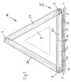
- a warning triangle 10 is shown with a base body 12, the four Legs 14, 16, which are the rear legs not shown, as well as a horizontal and two articulated has reflecting strips 22, 24, 26.
- the horizontal bar 22 has Projections 30, 32, 34 on, which with corresponding recesses 36, of the base body 12 are operatively connectable.
- the recesses 36 are formed as through openings which are formed by the projections 30, 32, 34 are traversable.
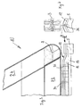
- the projections 30, 32, 34 are designed such that they can be connected with their recesses 36 in a positive and non-positive manner are. It can also be seen that the projections 30, 32, 34 on the bar 22nd are integrally formed, the free ends of these projections having holding bodies 44 (Fig. 2) are firmly connected.
- the base body 12 is designed so that the Legs 14-20 articulated and in an inoperative operating position below the Base body 12 are positionable.
- the pillars 14-20 are in yours folded state held by the holding bodies 44 and with Spaced from each other.
- the base body 12 and the holding body 44 are made of Plastic formed. Furthermore, it can be seen that the base body 12 in the Cross-section is V-shaped, so that the legs in the face of the ground Side can be accommodated.
- the free ends of the projections 30, 32, 34 are like this dimensioned that they can be introduced into openings of the holding body 44 and are immovably connectable with this.
- the Holding bodies 44 are tree-like and have receptacles for the pillars 14-20 so that they do not join in Be in touch, which prevents unwanted noise (rattling) become.
- the frame of the proposed warning triangle thus essentially exists only from the base body 12, on which the legs 14-20 by clipping are created, and the holding bodies 44, on the one hand, a fixed connection between the projections 30, 32, 34 and the base body 12 and on the other hand ensure that the pillars, which are regularly made of steel exist, not in contact with each other.
Description
- Fig. 1
- ein Warndreieck in Explosionsdarstellung,
- Fig. 2
- einen Basiskörper in vertikaler Draufsicht und
- Fig. 3
- einen Haltekörper in vertikalem Querschnitt und vergrößert dargestellt.
Claims (7)
- Warndreieck (10) mit einem Basiskörper (12), der Standbeine (14-20) sowie eine waagerechte Leiste (22) und zwei angelenkte rückstrahlende Leisten (24, 26) trägt, wobei die waagerechte Leiste (22) Vorsprünge (30, 32, 34) bzw. Ausnehmungen aufweist, die mit entsprechenden Ausnehmungen (36) bzw. Vorsprüngen des Basiskörpers (12) betriebsgemäß verbindbar sind,
dadurch gekennzeichnet, dass die freien Enden der Vorsprünge (30, 32, 34) mit für die am Basiskörper (12) angelenkten Standbeine (14, 16) vorgesehenen Haltekörpern (44) verbindbar sind. - Warndreieck nach Anspruch 1,
dadurch gekennzeichnet, daß die Ausnehmungen (36) als durchgehende Öffnungen ausgebildet sind, die von den Vorsprüngen (30, 32, 34) durchquert sind. - Warndreieck nach Anspruch 1 oder 2,
dadurch gekennzeichnet, daß die Vorsprünge (30, 32, 34) mit ihren Ausnehmungen (36) form- und/oder kraftschlüssig verbindbar sind. - Warndreieck nach einem der Ansprüche 1 bis 3,
dadurch gekennzeichnet, daß die Vorsprünge (30, 32, 34) an der Leiste (22) bzw. am Basiskörper angeformt sind. - Warndreieck nach einem der Ansprüche 1 - 4,
dadurch gekennzeichnet, daß die Haltekörper (44) mit den Vorsprüngen (30, 32, 34) lösbar verbindbar sind. - Warndreieck nach einem der Ansprüche 1 bis 5, an dessen Basiskörper (12) die Standbeine (14, 16) angelenkt und in unwirksamer Betriebsstellung unterhalb des Basiskörpers (12) positionierbar sind,
dadurch gekennzeichnet, daß die Standbeine (14,16) in ihrem zusammengeklappten Zustand von dem Haltekörper (44) gehalten und mit Abstand zueinander angeordnet sind. - Warndreieck nach Anspruch 6,
dadurch gekennzeichnet, daß der Basiskörper (12) sowie der Haltekörper (44) aus Kunststoff bestehen.
Applications Claiming Priority (2)
| Application Number | Priority Date | Filing Date | Title |
|---|---|---|---|
| DE19628746A DE19628746A1 (de) | 1996-07-17 | 1996-07-17 | Warndreieck |
| DE19628746 | 1996-07-17 |
Publications (3)
| Publication Number | Publication Date |
|---|---|
| EP0819577A2 EP0819577A2 (de) | 1998-01-21 |
| EP0819577A3 EP0819577A3 (de) | 1998-12-09 |
| EP0819577B1 true EP0819577B1 (de) | 2002-10-09 |
Family
ID=7800022
Family Applications (1)
| Application Number | Title | Priority Date | Filing Date |
|---|---|---|---|
| EP97110992A Expired - Lifetime EP0819577B1 (de) | 1996-07-17 | 1997-07-02 | Warndreieck |
Country Status (5)
| Country | Link |
|---|---|
| EP (1) | EP0819577B1 (de) |
| AT (1) | ATE225721T1 (de) |
| DE (2) | DE19628746A1 (de) |
| ES (1) | ES2183051T3 (de) |
| MY (1) | MY120423A (de) |
Families Citing this family (3)
| Publication number | Priority date | Publication date | Assignee | Title |
|---|---|---|---|---|
| KR100393299B1 (ko) * | 2001-02-13 | 2003-07-31 | 최성준 | 절첩식 받침구성을 갖는 안전표지 삼각대 |
| DE10250042A1 (de) * | 2002-10-25 | 2004-05-06 | Geka Günther & Kastl GmbH | Gestell für Warndreiecke |
| CN109849779A (zh) * | 2019-01-23 | 2019-06-07 | 浙江吉利汽车研究院有限公司 | 一种三角警示牌 |
Family Cites Families (7)
| Publication number | Priority date | Publication date | Assignee | Title |
|---|---|---|---|---|
| DE8228562U1 (de) * | 1983-01-27 | Müller, Hermann | Warndreieck | |
| DE1998435U (de) | 1968-07-22 | 1968-12-12 | Hermann Nier K G | Warndreieck zur verkehrssicherung. |
| DE7203863U (de) * | 1972-02-02 | 1972-05-10 | Kastl M | Mittel zum Befestigen eines Warnschildes oder eines klappbaren Warndreiecks mit der Stellvorrichtung |
| US3806234A (en) * | 1972-10-16 | 1974-04-23 | Dominion Auto Access | Foldable emergency reflecting device |
| ES206085Y (es) * | 1973-09-29 | 1976-06-16 | Butlers Limited | Disposicion de senal de aviso. |
| GB8823898D0 (en) * | 1988-10-12 | 1988-11-16 | Aph Road Safety Ltd | Hazard warning devices |
| US5551370A (en) * | 1995-01-23 | 1996-09-03 | Hwang; Wen-Chin | Warning triangle assembly |
-
1996
- 1996-07-17 DE DE19628746A patent/DE19628746A1/de not_active Ceased
-
1997
- 1997-07-02 ES ES97110992T patent/ES2183051T3/es not_active Expired - Lifetime
- 1997-07-02 DE DE59708412T patent/DE59708412D1/de not_active Expired - Fee Related
- 1997-07-02 EP EP97110992A patent/EP0819577B1/de not_active Expired - Lifetime
- 1997-07-02 AT AT97110992T patent/ATE225721T1/de not_active IP Right Cessation
- 1997-07-09 MY MYPI97003118A patent/MY120423A/en unknown
Also Published As
| Publication number | Publication date |
|---|---|
| DE19628746A1 (de) | 1998-01-22 |
| DE59708412D1 (de) | 2002-11-14 |
| ATE225721T1 (de) | 2002-10-15 |
| MY120423A (en) | 2005-10-31 |
| EP0819577A2 (de) | 1998-01-21 |
| ES2183051T3 (es) | 2003-03-16 |
| EP0819577A3 (de) | 1998-12-09 |
Similar Documents
| Publication | Publication Date | Title |
|---|---|---|
| DE19638156B4 (de) | Aufbau für oberen Karosserieabschnitt einer Fahrzeugkarosserie | |
| DE4204825C2 (de) | Wagenkasten für Kraftfahrzeuge, insbesondere Personenkraftwagen | |
| DE10023193B4 (de) | Fahrzeugaufbau für einen Vorderwagen eines Kraftfahrzeugs | |
| DE3936418C1 (de) | ||
| EP0592855B1 (de) | Sonnenblende für Fahrzeuge | |
| DE4303006C2 (de) | Rückenlehne für Fahrzeugsitze, insbesondere Kraftfahrzeugsitze | |
| DE19706701A1 (de) | Verstärkungsstreifen für extrudierte Scheibenwischblätter | |
| EP0819577B1 (de) | Warndreieck | |
| EP0155988B1 (de) | Gleitschutzvorrichtung für Fahrzeugreifen | |
| DE60108638T2 (de) | Ablenkvorrichtung für förderer | |
| DE19912183A1 (de) | Längsgesickter Träger, insbesondere Dachträger für ein Kraftfahrzeug | |
| EP0536547B1 (de) | Wagenheber | |
| DE2855325A1 (de) | Absauganlage, insbesondere fuer die kraftfahrzeugindustrie | |
| EP0995373A1 (de) | Reihenverbindung für Mehrzweckstühle | |
| DE3420418C2 (de) | ||
| DE10340357A1 (de) | Knotenstruktur für eine Fahrzeugkarosserie | |
| DE3246509C2 (de) | Lagerung für die Hinterachse und die Bremswelle eines Kinderfahrzeuges | |
| EP0009705B1 (de) | Anschlussschiene, insbesondere für Trennwandelemente | |
| EP0984872B1 (de) | Rückenlehnenträger für eine rückenlehne eines sitzes, insbesondere eines fahrzeugsitzes | |
| DE10121589A1 (de) | Kofferhalterung für Zweiradfahrzeuge | |
| DE4445250A1 (de) | Dachverkleidungsplatte in einem Fahrzeuginnenraum | |
| DE3237289A1 (de) | Aussenrueckblickspiegel | |
| DE202017106964U1 (de) | Führungsschiene für einen Gurthöhenversteller | |
| DE202004016224U1 (de) | Sichtzeichen zur Anbringung an einem Zaunfeld eines Absperr- oder Bauzauns | |
| DE6912343U (de) | Schutzleiste fuer stossstangen von kraftfahrzeugen. |
Legal Events
| Date | Code | Title | Description |
|---|---|---|---|
| PUAI | Public reference made under article 153(3) epc to a published international application that has entered the european phase |
Free format text: ORIGINAL CODE: 0009012 |
|
| AK | Designated contracting states |
Kind code of ref document: A2 Designated state(s): AT DE ES FR GB IT NL SE |
|
| PUAL | Search report despatched |
Free format text: ORIGINAL CODE: 0009013 |
|
| AK | Designated contracting states |
Kind code of ref document: A3 Designated state(s): AT BE CH DE DK ES FI FR GB GR IE IT LI LU MC NL PT SE |
|
| 17P | Request for examination filed |
Effective date: 19990609 |
|
| AKX | Designation fees paid |
Free format text: AT DE ES FR GB IT NL SE |
|
| 17Q | First examination report despatched |
Effective date: 20010223 |
|
| GRAG | Despatch of communication of intention to grant |
Free format text: ORIGINAL CODE: EPIDOS AGRA |
|
| GRAG | Despatch of communication of intention to grant |
Free format text: ORIGINAL CODE: EPIDOS AGRA |
|
| GRAH | Despatch of communication of intention to grant a patent |
Free format text: ORIGINAL CODE: EPIDOS IGRA |
|
| GRAH | Despatch of communication of intention to grant a patent |
Free format text: ORIGINAL CODE: EPIDOS IGRA |
|
| GRAA | (expected) grant |
Free format text: ORIGINAL CODE: 0009210 |
|
| AK | Designated contracting states |
Kind code of ref document: B1 Designated state(s): AT DE ES FR GB IT NL SE |
|
| REF | Corresponds to: |
Ref document number: 225721 Country of ref document: AT Date of ref document: 20021015 Kind code of ref document: T |
|
| REG | Reference to a national code |
Ref country code: GB Ref legal event code: FG4D Free format text: NOT ENGLISH |
|
| REF | Corresponds to: |
Ref document number: 59708412 Country of ref document: DE Date of ref document: 20021114 |
|
| PG25 | Lapsed in a contracting state [announced via postgrant information from national office to epo] |
Ref country code: SE Free format text: LAPSE BECAUSE OF FAILURE TO SUBMIT A TRANSLATION OF THE DESCRIPTION OR TO PAY THE FEE WITHIN THE PRESCRIBED TIME-LIMIT Effective date: 20030109 |
|
| GBT | Gb: translation of ep patent filed (gb section 77(6)(a)/1977) |
Effective date: 20030204 |
|
| REG | Reference to a national code |
Ref country code: ES Ref legal event code: FG2A Ref document number: 2183051 Country of ref document: ES Kind code of ref document: T3 |
|
| ET | Fr: translation filed | ||
| PLBE | No opposition filed within time limit |
Free format text: ORIGINAL CODE: 0009261 |
|
| STAA | Information on the status of an ep patent application or granted ep patent |
Free format text: STATUS: NO OPPOSITION FILED WITHIN TIME LIMIT |
|
| 26N | No opposition filed |
Effective date: 20030710 |
|
| PGFP | Annual fee paid to national office [announced via postgrant information from national office to epo] |
Ref country code: GB Payment date: 20050621 Year of fee payment: 9 |
|
| PGFP | Annual fee paid to national office [announced via postgrant information from national office to epo] |
Ref country code: AT Payment date: 20050628 Year of fee payment: 9 |
|
| PGFP | Annual fee paid to national office [announced via postgrant information from national office to epo] |
Ref country code: FR Payment date: 20050712 Year of fee payment: 9 |
|
| PGFP | Annual fee paid to national office [announced via postgrant information from national office to epo] |
Ref country code: NL Payment date: 20050714 Year of fee payment: 9 |
|
| PG25 | Lapsed in a contracting state [announced via postgrant information from national office to epo] |
Ref country code: GB Free format text: LAPSE BECAUSE OF NON-PAYMENT OF DUE FEES Effective date: 20060702 Ref country code: AT Free format text: LAPSE BECAUSE OF NON-PAYMENT OF DUE FEES Effective date: 20060702 |
|
| PG25 | Lapsed in a contracting state [announced via postgrant information from national office to epo] |
Ref country code: NL Free format text: LAPSE BECAUSE OF NON-PAYMENT OF DUE FEES Effective date: 20070201 |
|
| GBPC | Gb: european patent ceased through non-payment of renewal fee |
Effective date: 20060702 |
|
| NLV4 | Nl: lapsed or anulled due to non-payment of the annual fee |
Effective date: 20070201 |
|
| REG | Reference to a national code |
Ref country code: FR Ref legal event code: ST Effective date: 20070330 |
|
| PGFP | Annual fee paid to national office [announced via postgrant information from national office to epo] |
Ref country code: DE Payment date: 20070719 Year of fee payment: 11 |
|
| PGFP | Annual fee paid to national office [announced via postgrant information from national office to epo] |
Ref country code: ES Payment date: 20070727 Year of fee payment: 11 |
|
| PGFP | Annual fee paid to national office [announced via postgrant information from national office to epo] |
Ref country code: IT Payment date: 20070723 Year of fee payment: 11 |
|
| PG25 | Lapsed in a contracting state [announced via postgrant information from national office to epo] |
Ref country code: FR Free format text: LAPSE BECAUSE OF NON-PAYMENT OF DUE FEES Effective date: 20060731 |
|
| PG25 | Lapsed in a contracting state [announced via postgrant information from national office to epo] |
Ref country code: DE Free format text: LAPSE BECAUSE OF NON-PAYMENT OF DUE FEES Effective date: 20090203 |
|
| PG25 | Lapsed in a contracting state [announced via postgrant information from national office to epo] |
Ref country code: IT Free format text: LAPSE BECAUSE OF NON-PAYMENT OF DUE FEES Effective date: 20080702 |
|
| REG | Reference to a national code |
Ref country code: ES Ref legal event code: FD2A Effective date: 20080703 |
|
| PG25 | Lapsed in a contracting state [announced via postgrant information from national office to epo] |
Ref country code: ES Free format text: LAPSE BECAUSE OF NON-PAYMENT OF DUE FEES Effective date: 20080703 |