EP0819082B1 - Verfahren und vorrichtung zum dekorieren von gebinden mit gewölbten oberflächen - Google Patents
Verfahren und vorrichtung zum dekorieren von gebinden mit gewölbten oberflächen Download PDFInfo
- Publication number
- EP0819082B1 EP0819082B1 EP96904725A EP96904725A EP0819082B1 EP 0819082 B1 EP0819082 B1 EP 0819082B1 EP 96904725 A EP96904725 A EP 96904725A EP 96904725 A EP96904725 A EP 96904725A EP 0819082 B1 EP0819082 B1 EP 0819082B1
- Authority
- EP
- European Patent Office
- Prior art keywords
- containers
- backing web
- conveyor
- heating
- speed
- Prior art date
- Legal status (The legal status is an assumption and is not a legal conclusion. Google has not performed a legal analysis and makes no representation as to the accuracy of the status listed.)
- Expired - Lifetime
Links
Images

Classifications
-
- B—PERFORMING OPERATIONS; TRANSPORTING
- B65—CONVEYING; PACKING; STORING; HANDLING THIN OR FILAMENTARY MATERIAL
- B65C—LABELLING OR TAGGING MACHINES, APPARATUS, OR PROCESSES
- B65C3/00—Labelling other than flat surfaces
- B65C3/06—Affixing labels to short rigid containers
- B65C3/08—Affixing labels to short rigid containers to container bodies
- B65C3/14—Affixing labels to short rigid containers to container bodies the container being positioned for labelling with its centre-line vertical
- B65C3/16—Affixing labels to short rigid containers to container bodies the container being positioned for labelling with its centre-line vertical by rolling the labels onto cylindrical containers, e.g. bottles
-
- B—PERFORMING OPERATIONS; TRANSPORTING
- B41—PRINTING; LINING MACHINES; TYPEWRITERS; STAMPS
- B41M—PRINTING, DUPLICATING, MARKING, OR COPYING PROCESSES; COLOUR PRINTING
- B41M5/00—Duplicating or marking methods; Sheet materials for use therein
- B41M5/025—Duplicating or marking methods; Sheet materials for use therein by transferring ink from the master sheet
- B41M5/035—Duplicating or marking methods; Sheet materials for use therein by transferring ink from the master sheet by sublimation or volatilisation of pre-printed design, e.g. sublistatic
- B41M5/0358—Duplicating or marking methods; Sheet materials for use therein by transferring ink from the master sheet by sublimation or volatilisation of pre-printed design, e.g. sublistatic characterised by the mechanisms or artifacts to obtain the transfer, e.g. the heating means, the pressure means or the transport means
-
- B—PERFORMING OPERATIONS; TRANSPORTING
- B44—DECORATIVE ARTS
- B44C—PRODUCING DECORATIVE EFFECTS; MOSAICS; TARSIA WORK; PAPERHANGING
- B44C1/00—Processes, not specifically provided for elsewhere, for producing decorative surface effects
- B44C1/16—Processes, not specifically provided for elsewhere, for producing decorative surface effects for applying transfer pictures or the like
- B44C1/165—Processes, not specifically provided for elsewhere, for producing decorative surface effects for applying transfer pictures or the like for decalcomanias; sheet material therefor
- B44C1/17—Dry transfer
- B44C1/1712—Decalcomanias applied under heat and pressure, e.g. provided with a heat activable adhesive
-
- B—PERFORMING OPERATIONS; TRANSPORTING
- B65—CONVEYING; PACKING; STORING; HANDLING THIN OR FILAMENTARY MATERIAL
- B65C—LABELLING OR TAGGING MACHINES, APPARATUS, OR PROCESSES
- B65C9/00—Details of labelling machines or apparatus
- B65C9/08—Label feeding
- B65C9/18—Label feeding from strips, e.g. from rolls
- B65C9/1865—Label feeding from strips, e.g. from rolls the labels adhering on a backing strip
- B65C9/1869—Label feeding from strips, e.g. from rolls the labels adhering on a backing strip and being transferred directly from the backing strip onto the article
- B65C9/1873—Label feeding from strips, e.g. from rolls the labels adhering on a backing strip and being transferred directly from the backing strip onto the article the transfer involving heating means, e.g. for decals
-
- B—PERFORMING OPERATIONS; TRANSPORTING
- B41—PRINTING; LINING MACHINES; TYPEWRITERS; STAMPS
- B41P—INDEXING SCHEME RELATING TO PRINTING, LINING MACHINES, TYPEWRITERS, AND TO STAMPS
- B41P2219/00—Printing presses using a heated printing foil
- B41P2219/40—Material or products to be decorated or printed
- B41P2219/43—Three-dimensional articles
-
- Y—GENERAL TAGGING OF NEW TECHNOLOGICAL DEVELOPMENTS; GENERAL TAGGING OF CROSS-SECTIONAL TECHNOLOGIES SPANNING OVER SEVERAL SECTIONS OF THE IPC; TECHNICAL SUBJECTS COVERED BY FORMER USPC CROSS-REFERENCE ART COLLECTIONS [XRACs] AND DIGESTS
- Y10—TECHNICAL SUBJECTS COVERED BY FORMER USPC
- Y10T—TECHNICAL SUBJECTS COVERED BY FORMER US CLASSIFICATION
- Y10T156/00—Adhesive bonding and miscellaneous chemical manufacture
- Y10T156/17—Surface bonding means and/or assemblymeans with work feeding or handling means
- Y10T156/1702—For plural parts or plural areas of single part
- Y10T156/1705—Lamina transferred to base from adhered flexible web or sheet type carrier
-
- Y—GENERAL TAGGING OF NEW TECHNOLOGICAL DEVELOPMENTS; GENERAL TAGGING OF CROSS-SECTIONAL TECHNOLOGIES SPANNING OVER SEVERAL SECTIONS OF THE IPC; TECHNICAL SUBJECTS COVERED BY FORMER USPC CROSS-REFERENCE ART COLLECTIONS [XRACs] AND DIGESTS
- Y10—TECHNICAL SUBJECTS COVERED BY FORMER USPC
- Y10T—TECHNICAL SUBJECTS COVERED BY FORMER US CLASSIFICATION
- Y10T156/00—Adhesive bonding and miscellaneous chemical manufacture
- Y10T156/17—Surface bonding means and/or assemblymeans with work feeding or handling means
- Y10T156/1702—For plural parts or plural areas of single part
- Y10T156/1744—Means bringing discrete articles into assembled relationship
- Y10T156/1768—Means simultaneously conveying plural articles from a single source and serially presenting them to an assembly station
- Y10T156/1771—Turret or rotary drum-type conveyor
Definitions
- the invention relates to a continuous process, in which the container with a superimposed self-rotation on a transport track and the decorations on a carrier web with constant speeds and be moved tangentially past a transmission location, where the decorations are applied to the Containers are transferred.
- the invention further relates to a corresponding one Device consisting of a drivable endless Transport track with evenly spaced, drivable and rotating receptacles for the containers a drivable endless carrier track with even spaced decor and from a place of transmission trained contact area between the transport track and the carrier web, being in the area of the transfer location Means to exert pressure and means are arranged to heat the decor.
- the decorative motif is created using known printing technology printed on a carrier web in such a way that it by means of an adhesive of lower adhesive strength with the carrier web connected and with another adhesive higher adhesive force is coated.
- a so made Carrier web is in with the containers to be decorated Brought in contact. By pressure and heat in this contact area the decor separates from the carrier web and connects to the container at the same time. The heat supply takes place via the container.
- a continuous process and an apparatus therefor in which the thermal transfer process also applies to containers with low heat capacity e.g. Plastic containers can be used are described in DE 44 37 379.1.
- the carrier web is printed in a print motif load-bearing individual sections separated and on heated order segments transferred on at equal intervals an order funding are arranged.
- This order funding temporarily takes over the containers in the way that a container is assigned to each order segment is.
- the decor is then removed from the Transfer the individual section to the container. This method but required because of a large number of individual operations a high expenditure on equipment.
- a major disadvantage is that the movements of the transport path and run the carrier web in the same direction. This calls for an equal division of the containers the transport track and the decorations on the carrier track what can only be achieved with increased technical effort is. This also results in a long transmission time.
- the containers printed using the thermal transfer process usually require additional heat treatment, so that the transferred color image gets an increased gloss, the paints dried and the adhesion of the surface is improved.
- DE 44 27 870.5 describes that fresh printed structures with the still damp print image above a separate discharge in a separate oven to transport.
- the particular advantage of the invention lies in the extreme high peripheral speed of the containers.
- the minimal touch time also prevents you Temperature transfer from the carrier web to the container, which is particularly advantageous for plastic containers.
- the two temperature-dependent layers remain unaffected by adhesive on the carrier web.
- the guide element a movable heating element connected upstream for the carrier web.
- the contact area between the heating element and the carrier web can be changed continuously from zero to maximum.
- the heating time can thus be advantageous be adjusted to the speed of the carrier web.
- the convex design of the guide surface of the heating element increases the contact ability and improves the Heat transfer.
- This swivel arm has a deflection roller for the carrier web with which the contact surface of the radiator is changeable with the carrier web.
- the heating element or the swivel arm can have its own Own actuator or with appropriate suspension driven by their own weight.
- the corresponding regulation can take place automatically.
- the movable heating element takes on the task of a preheater and the print head that of the actual one Heating element.
- the device for decorating is mainly from a transport device for the containers and from a transport device for the decorations, both a common interface for the transmission of the Own decorations on the containers.
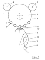
- the Carousel 1 is the transport device for Container designed as a rotatable carousel 1.
- the Carousel 1 has a drive, not shown, one Input station 2, an output station 3 and a transport track 4 for the container 5.
- On the transport track 4 are receiving means 6 for the at equal intervals decorating containers 5 arranged. This means of reception 6 are designed to rotate freely.
- the transport device for the decor consists of a pulled by a drive, not shown Carrier track 7 and corresponding guide elements for this carrier web 7.
- the carrier web 7 is in known manner trained and carries by means of a Adhesive with lower adhesive strength at equal intervals arranged decorations. The surfaces of the decorations are with another adhesive with greater adhesive strength overdrawn.
- the guide elements consist of at least one deflection roller 8, a pivotable heating element 9 and one Printhead 10 slidable in the direction of the container 5.
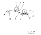
- the pivotable heating element 9 has an outer guide surface 12, which is expediently convex is and an upper pivot. Around that pivot point the heating element 9 by a drive of conventional type in the direction transverse to the direction of movement of the carrier web 7 pivotable. This results in a different size, contact surface dependent on the swivel angle between the guide surface 12 and the carrier web 7.
- the print head 10 also has an outer, preferably flat guide surface 11 and is biased by a Compression spring or by another conventional Drive system driven in the direction of the carousel 1.
- the transport track 4 for the container 5 and the carrier track 7 for the decorations affect each other in the area of Print head 10, the movements of the transport path 4 and the carrier web 7 are opposite. Thus comes it in this area for direct contact between the Carrier web 7 and the container 5 and thus also with the freely rotatable receiving means 6.
- a deflection roller 13 may be arranged in a special way Direction of movement of the carrier web 7 after the print head 10 .
- a deflection roller 13 lies the Location of the deflection roller 13 outside the transport path 4 at a distance from the printhead 10 that is greater than the distance of the container 5, which makes it to contact the Carrier web 7 freed from the decor and the next container 5 is coming.
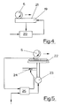
- the Print head 10 ' has an outer guide surface 11', a mechanical preset 14 and one pneumatic actuator 15.
- the heating element 9 ' has an outer, convex guide surface 12 'equipped and has an operative connection with a swivel arm 16.
- This swivel arm 16 is on his head with a pulley 17 and with one Spacer roller 18 equipped.
- the swivel arm 16 has continue a drive, not shown, with which the Position of the deflection roller 17 relative to the heating element 9 ' is changeable. This position is dependent on the speed of the carrier web 7 set and determined the size of the contact area between the heating element 9 'and the carrier web 7. At a slow speed the deflection roller 17 is positioned closer and at a fast speed further from Printhead 10 'removed.
- the spacer roller 18 holds the Carrier web 7 in the area in front of the deflection roller 17 of the Heating element 9 'remote.
- the carrier web 7 ' is in the position when the roll, not shown, with the carrier web 7 expired is.
- the heat aftertreatment device exists from a fixed and electrically operated Heat plate 19 and one, to a setpoint temperature adjustable controller 20 and is behind the transfer location set up.
- the hot plate 19 can plan with one or equipped with a concave heating surface 21 that should depend on whether the transport direction the container 5 is a linear or a circular path describes.
- the transport path 4 of the Carousels 1 also for heat treatment of the containers 5 used is a concave shaped heat surface 21 advantageous. With the right choice of the shape of the heating surface 21 can over the length of the heating surface 21 certain heat treatment times can be defined.
- a heat treatment device exists mainly from a nozzle head 22, one temperature-controlled hot air generator 23, a volume-controlled Bypass valve 24 and a temperature and Flow regulator 25.
- the containers 5 are again linear or linear Circular path. For the rotation of the container 5 is a separate one Drive required.
- the setpoint temperature for controller 20 or for the temperature and quantity controller 25 is taken into account to specify the material of the container 5.
- container 5 made of plastic therefore require a special one Attention. To avoid undesirable deformations it may be appropriate to use container 5 made of plastic additionally with injected compressed air stabilize.
- the operation of the device is based on the Fig. 1 explains.
- the carousel 1 and the carrier web 7 are each with desired but constant speeds driven.
- the movements are oriented in opposite directions.
- the from the input station 2 to the recording means 6 parked containers 5 are on the conveyor 4 transported in the direction of the print head 10.
- each container 5 and the carrier web 7 adjusts in the area of the print head 10, there is a rotation of the on the receiving means 6 freely rotatable container 5. This turns on the container 5 a peripheral speed in the size of the speed the carrier web 7 a. The container 5 rolls on the carrier web 7 under the pressure exerted by the print head 10 goes out. The decor separates from the carrier web and adheres to the container 5.
- the containers 5 then pass through one of the heat treatment devices.
Landscapes
- Labeling Devices (AREA)
- Auxiliary Devices For And Details Of Packaging Control (AREA)
Description
- Fig. 1:
- eine schematische Draufsicht auf die Vorrichtung zum Dekorieren,
- Fig. 2:
- eine zweckmäßige Ausführung für den Antrieb der Gebinde durch die Trägerbahn,
- Fig. 3:
- eine zweckmäßige Ausführung für die Heizeinrichtung der Trägerbahn,
- Fig. 4:
- eine Wärmenachbehandlungseinrichtung und
- Fig. 5:
- eine andere Wärmenachbehandlungseinrichtung.
- 1
- Karussell
- 2
- Eingabestation
- 3
- Ausgabestation
- 4
- Transportbahn
- 5
- Gebinde
- 6
- Aufnahmemittel
- 7, 7'
- Trägerbahn
- 8
- Umlenkrolle
- 9, 9'
- Heizelement
- 10, 10'
- Druckkopf
- 11, 11'
- Führungsfläche des Druckkopfes
- 12, 12'
- Führungsfläche des Heizelementes
- 13
- Umlenkrolle
- 14
- Voreinstelleinrichtung
- 15
- pneumatischer Antrieb
- 16
- Schwenkarm
- 17
- Umlenkrolle
- 18
- Abstandsrolle
- 19
- Wärmeplatte
- 20
- Regler
- 21
- Wärmefläche
- 22
- Düsenkopf
- 23
- Heißluftgenerator
- 24
- Bypassventil
- 25
- Temperatur- und Mengenregler
Claims (22)
- Verfahren zum kontinuierlichen Dekorieren von Gebinden mit gewölbten Oberflächen, bei dem die Gebinde (5) im Bereich eines Übertragungsortes mit einer überlagerten Eigenrotation auf einer Transportbahn (4) und die Dekors auf einer Trägerbahn (7, 7') mit konstanten Geschwindigkeiten und tangierend an dem Übertragungort vorbeibewegt werden, wo die Dekors nacheinander unter Druck und Wärme auf die Gebinde (5) übertragen werden,
dadurch gekennzeichnet, dassdie Trägerbahn (7, 7') ziehend belastet von einer Rolle abgerollt wird,im Bereich des Übertragungsortes die Bewegung der Abschnitte der Transportbahn (4) und der Trägerbahn (7, 7') entgegengerichtet und die Bewegungen der Gebinde (5) und der Trägerbahn (7, 7') gleichgerichtet sind, wobei sich der Abstand der Gebinde (5) auf der Transportbahn (4) zur Geschwindigkeit der Transportbahn (4) genauso verhält wie die Abstand der Dekors auf der Trägerbahn (7, 7') zur Geschwindigkeit der Trägerbahn (7, 7'), und wobei die rotierenden Gebinde (5) im Bereich des Übertragungsortes auf eine Umfangsgeschwindigkeit beschleunigt werden, die der Geschwindigkeit der Trägerbahn (7, 7') entspricht, unddie notwendige Wärme auf die Trägerbahn (7, 7') gebracht wird. - Verfahren nach Anspruch 1, dadurch gekennzeichnet, daß der Antrieb für die Rotation der Gebinde (5) durch die Bewegung der Trägerbahn (7, 7') erfolgt.
- Verfahren nach Anspruch 2, dadurch gekennzeichnet, daß jedes Gebinde (5) bereits vor dem Übertragungsort durch die Trägerbahn (7, 7') beschleunigt wird.
- Verfahren nach Anspruch 1, dadurch gekennzeichnet, daß die notwendige Wärme vor dem oder am Übertragungsort in die Trägerbahn (7, 7') eingespeist wird.
- Verfähren nach Anspruch 4, dadurch gekennzeichnet, daß sich die Erwärmzeit der Trägerbahn (7, 7') nach der Geschwindigkeit der Trägerbahn (7, 7') richtet.
- Verfahren nach Anspruch 5, dadurch gekennzeichnet, daß die Regelung der Erwärmzeit der Trägerbahn (7, 7') automatisch erfolgt.
- Verfahren nach Anspruch 1, dadurch gekennzeichnet, daß die Gebinde (5) aus Kunststoff durch eingeblasene Preßluft stabilisiert werden.
- Vorrichtung zum kontinuierlichen Dekorieren von Gebinden mit gewölbten Oberflächen, bestehenddadurch gekennzeichnet, dassaus einer antreibbaren endlosen Transportbahn (4) mit gleichmäßig beabstandeten, antreibbaren und rotierbaren Aufnahmemitteln (6) für die Gebinde (5),aus einer antreibbaren endlosen Trägerbahn (7, 7') mit gleichmäßig beabstandeten Dekors undaus einem Kontaktbereich zwischen der Transportbahn (4) und der Trägerbahn (7, 7'), der als Übertragungsort ausgebildet ist,wobei im Bereich des Übertragungsortes Mittel zur Ausübung eines Drucks auf die Trägerbahn (7, 7') in Richtung der Gebinde (5) und vor oder am Übertragungsort Mittel zur Erwärmung der Dekors angeordnet sind,die Trägerbahn (7, 7') ziehend belastet von einer Rolle abrollbar ist,die Antriebsmittel für die Transportbahn (4) und die Trägerbahn (7, 7') für entgegengesetzte Bewegungsrichtungen der am Übertragungsort befindlichen Abschnitte der Transportbahn (4) und der Trägerbahn (7, 7') ausgelegt sind,die Antriebsmittel für die Gebinde (5) für eine zur Trägerbahn (7, 7') gleichgerichteten Bewegungsrichtung ausgelegt sind,die Mittel zur Druckausübung und die Mittel zur Erwärmung als Führungselement ausgebildet sind, unddas Führungselement quer zur Bewegungsrichtung der Trägerbahn (7, 7') beweglich und vorgespannt ist und als Heizelement ausgebildet ist.
- Vorrichtung nach Anspruch 8, dadurch gekennzeichnet, daß die Aufnahmemittel (6) für die Gebinde (5) freidrehend ausgeführt sind und jedes Aufnahmemittel (6) über das Gebinde (5) von der Trägerbahn (7, 7') antreibbar ist.
- Vorrichtung nach Anspruch 9, dadurch gekennzeichnet, daß die Trägerbahn (7, 7') so geführt wird, daß sie mit einem vom Dekor befreiten Bereich Kontakt zu mindestens einem weiteren Gebilde (5) besitzt.
- Vorrichtung nach Anspruch 8, dadurch gekennzeichnet, daß die Aufnahmemittel (6) für die Gebinde (5) einen gesonderten Antrieb besitzen.
- Vorrichtung nach Anspruch 8, dadurch gekennzeichnet, daß die Aufnahmemittel (6) einen gesonderten Antrieb für eine Geschwindigkeit kleiner als die erforderliche besitzen und die erforderliche Geschwindigkeit durch den Kontakt der Gebinde (5) mit der Trägerbahn (7, 7') erzeugt wird.
- Vorrichtung nach wenigstens einem der Ansprüche 8 bis 12, dadurch gekennzeichnet, daß dem Führungselement ein bewegliches Heizelement (9, 9') mit einer Kontaktfläche vorgeordnet ist, wobei die Größe der Kontaktfläche zwischen dem Heizelement (9, 9') und der Trägerbahn (7, 7') stufenlos zwischen null und maximal veränderbar ist.
- Vorrichtung nach Anspruch 13,
dadurch gekennzeichnet, daß die Kontaktfläche des Heizelementes (9, 9') konvex ausgebildet ist. - Vorrichtung nach Anspruch 14,
dadurch gekennzeichnet, daß das bewegliche Heizelement (9, 9') schwenkbar ausgeführt ist und einen Stellantrieb für einen von der Geschwindigkeit der Trägerbahn (7, 7') abhängigen Schwenkweg besitzt. - Vorrichtung nach Anspruch 15,
dadurch gekennzeichnet, daß der Schwenkweg automatisch verstellbar ist. - Vorrichtung nach weinigtens einem der Ansprüche 14 bis 16,
dadurch gekennzeichnet, daß das bewegliche Heizelement (9, 9') mit einem seitlichen Drehpunkt und mit untenlie-gender Kontaktfläche ausgeführt ist und der Schwenkweg sich aus dem Verhältnis der Eigenmasse des Heizelementes (9, 9') und dem geschwindigkeitsbedingten Auftrieb der Trägerbahn (7, 7') ergibt. - Vorrichtung nach einem oder mehreren der Ansprüche 13 bis 17, dadurch gekennzeichnet, daß der Druckkopf (10, 10') als Heizelement und das bewegliche Heizelement (9, 9') als Vorwärmer ausgebildet ist.
- Vorrichtung nach Anspruch 8, dadurch gekennzeichnet, daß die Wärmequelle einer Nachbehandlungseinrichtung aus einer elektrisch betriebenen Wärmeplatte (19) mit einer planen oder konkaven Wärmefläche (21) und einem, auf eine Sollwerttemperatur einstellbaren Regler (20) besteht.
- Vorrichtung nach Anspruch 19, dadurch gekennzeichnet, daß sich die plane Wärmefläche (21) auf eine lineare Transportbahn und die konkave Wärmefläche (21) auf eine Kreistransportbahn der Gebinde (5) bezieht und die Länge der wirksamen Wärmefläche (21) für eine Sollnachwärmezeit definiert ist.
- Vorrichtung nach Anspruch 19 oder 20, dadurch gekennzeichnet, daß die Gebinde (5) auf der Transportbahn der Nachbehandlungseinrichtung freidrehend angeordnet sind und von der stationären Wärmeplatte (19) angetrieben werden.
- Vorrichtung nach Anspruch 8, dadurch gekennzeichnet, daß die Wärmequelle der Nachbehandlungseinrichtung aus einem Düsenkopf (22), einem temperaturgesteuerten Heißluftgenerator (23), einem mengengeregelten Bypassventil (24) und einem Temperatur- und Mengenregler (25) besteht und die Gebinde (5) einen separaten Antrieb für die Rotation besitzen.
Priority Applications (2)
| Application Number | Priority Date | Filing Date | Title |
|---|---|---|---|
| DE29624331U DE29624331U1 (de) | 1995-03-18 | 1996-03-02 | Vorrichtung zum Dekorieren von Gebinden mit gewölbten Oberflächen |
| EP02017417A EP1298064A1 (de) | 1995-03-18 | 1996-03-02 | Verfahren und Vorrichtung zum Dekorieren von Gebinden mit gewölbten Oberflächen |
Applications Claiming Priority (3)
| Application Number | Priority Date | Filing Date | Title |
|---|---|---|---|
| DE19509984 | 1995-03-18 | ||
| DE19509984A DE19509984C1 (de) | 1995-03-18 | 1995-03-18 | Verfahren und Vorrichtung zum Dekorieren von Gebinden mit gewölbten Oberflächen |
| PCT/DE1996/000365 WO1996029248A1 (de) | 1995-03-18 | 1996-03-02 | Verfahren und vorrichtung zum dekorieren von gebinden mit gewölbten oberflächen |
Related Child Applications (1)
| Application Number | Title | Priority Date | Filing Date |
|---|---|---|---|
| EP02017417A Division EP1298064A1 (de) | 1995-03-18 | 1996-03-02 | Verfahren und Vorrichtung zum Dekorieren von Gebinden mit gewölbten Oberflächen |
Publications (2)
| Publication Number | Publication Date |
|---|---|
| EP0819082A1 EP0819082A1 (de) | 1998-01-21 |
| EP0819082B1 true EP0819082B1 (de) | 2003-05-21 |
Family
ID=7757116
Family Applications (2)
| Application Number | Title | Priority Date | Filing Date |
|---|---|---|---|
| EP96904725A Expired - Lifetime EP0819082B1 (de) | 1995-03-18 | 1996-03-02 | Verfahren und vorrichtung zum dekorieren von gebinden mit gewölbten oberflächen |
| EP02017417A Withdrawn EP1298064A1 (de) | 1995-03-18 | 1996-03-02 | Verfahren und Vorrichtung zum Dekorieren von Gebinden mit gewölbten Oberflächen |
Family Applications After (1)
| Application Number | Title | Priority Date | Filing Date |
|---|---|---|---|
| EP02017417A Withdrawn EP1298064A1 (de) | 1995-03-18 | 1996-03-02 | Verfahren und Vorrichtung zum Dekorieren von Gebinden mit gewölbten Oberflächen |
Country Status (6)
| Country | Link |
|---|---|
| US (3) | US6098689A (de) |
| EP (2) | EP0819082B1 (de) |
| JP (1) | JP3713669B2 (de) |
| DE (3) | DE19509984C1 (de) |
| ES (1) | ES2200053T3 (de) |
| WO (1) | WO1996029248A1 (de) |
Families Citing this family (18)
| Publication number | Priority date | Publication date | Assignee | Title |
|---|---|---|---|---|
| DE19509984C1 (de) * | 1995-03-18 | 1996-10-02 | Wolfgang Fiwek | Verfahren und Vorrichtung zum Dekorieren von Gebinden mit gewölbten Oberflächen |
| DE19714794C2 (de) * | 1997-04-10 | 1999-04-01 | Wolfgang Fiwek | Verfahren und Einrichtung zum Dekorieren von Gebinden |
| US6531018B1 (en) | 1997-04-10 | 2003-03-11 | Heineken Technical Services B.V. | Method and device for decorating containers |
| US6796352B1 (en) * | 2000-08-09 | 2004-09-28 | Mcc Dec Tech Llc | Apparatus for applying heat-transfer labels onto objects |
| US6570600B2 (en) * | 2001-01-19 | 2003-05-27 | Impress Systems | Method and apparatus for direct cylinder printer |
| NL1021968C2 (nl) | 2002-11-21 | 2004-05-26 | Heineken Tech Services | Etiketteerinrichting voorzien van een oscillerende etikettenbaan-positioneringseenheid, alsmede werkwijze voor het aanbrengen van een etiket. |
| US7014284B2 (en) * | 2003-01-16 | 2006-03-21 | Morton William Bill | Ammunition having surface indicia and method of manufacture |
| US6998006B1 (en) | 2003-03-14 | 2006-02-14 | Jefferson Smurfit Corporation | System and method for configuring a heat transfer decorating machine for different package configurations |
| US6887333B1 (en) | 2003-03-14 | 2005-05-03 | Jefferson Smurfit Corporation | System and method for environmentally cleaning a package for a heat transfer decorating machine |
| US20050067111A1 (en) * | 2003-09-30 | 2005-03-31 | Mcc-Dec Tech, L.L.C. | System and associated method for high output label application |
| FR2865965B1 (fr) * | 2004-02-10 | 2007-11-30 | Cebal Sas | Procede permettant de decorer en grande cadence des recipients a paroi cylindrique |
| ITMN20050022A1 (it) * | 2005-04-18 | 2006-10-19 | Global Packaging Solutions S R L | Macchina per l'applicazione su bottiglie di etichette a film continuo con colla preapplicata |
| US20100101711A1 (en) * | 2007-03-26 | 2010-04-29 | Maximilian Zaher | Device and method for applying decoration, which adheres to a film, to an object |
| US20090110947A1 (en) * | 2007-10-31 | 2009-04-30 | Compal Electronics, Inc. | Apparatus and method of decorating a surface of a workpiece and decorated part |
| MX2011009657A (es) * | 2009-03-19 | 2011-09-28 | Graphic Packaging Int Inc | Metodo y aparato para aplicar etiquetas a un envase que gira sobre una torreta giratoria. |
| CA2664772C (en) | 2009-05-13 | 2010-02-16 | The Procter & Gamble Company | Label applicator having a heat idler |
| CA2664771C (en) * | 2009-05-13 | 2010-02-16 | The Procter & Gamble Company | Label applicator having a vacuum box |
| US8986475B2 (en) * | 2010-06-18 | 2015-03-24 | Mcc-Norwood, Llc | Heat transfer labeling machine with hot air treatment stations |
Family Cites Families (28)
| Publication number | Priority date | Publication date | Assignee | Title |
|---|---|---|---|---|
| US2674299A (en) * | 1952-03-20 | 1954-04-06 | George W Swift Jr Inc | Web corrugating machine |
| US2862832A (en) * | 1956-01-09 | 1958-12-02 | Dennison Mfg Co | Heat transfer |
| US2981432A (en) * | 1958-04-17 | 1961-04-25 | Dennison Mfg Co | Indicia-applying apparatus |
| FR83059E (fr) * | 1962-11-24 | 1964-06-05 | étiqueteuse | |
| US3616073A (en) * | 1969-11-18 | 1971-10-26 | Harris Intertype Corp | Double facer with safety means |
| US4648930A (en) * | 1975-10-01 | 1987-03-10 | Mers Herbert | Method of separating labels from a carrier strip |
| US4475969A (en) * | 1978-01-19 | 1984-10-09 | Avery International Corporation | Label roll manufacture |
| CA1154299A (en) * | 1980-07-08 | 1983-09-27 | Daniel Kerwin | Method and apparatus for applying decals to articles |
| JPS5873740A (ja) * | 1981-10-28 | 1983-05-04 | Nippon Light Metal Co Ltd | 鋳物用アルミニウム合金 |
| DE3241041A1 (de) * | 1982-11-06 | 1984-05-03 | Herlan & Co Maschinenfabrik GmbH, 7500 Karlsruhe | Uebertragungsdruckverfahren und vorrichtung zu seiner ausfuehrung |
| EP0183440B1 (de) * | 1984-11-15 | 1991-08-21 | Ajinomoto Co., Inc. | Transferdruck |
| US4973374A (en) * | 1986-09-08 | 1990-11-27 | Electrocal, Inc. | Method for applying labels to curved objects |
| US4806197A (en) * | 1987-02-18 | 1989-02-21 | Dinagraphics, Inc. | Continuous motion round bottle turret |
| DE4014274C1 (en) * | 1990-05-04 | 1991-06-27 | Krones Ag Hermann Kronseder Maschinenfabrik, 8402 Neutraubling, De | Container shrink label application method - has hot melt adhesive placed on leading label edge prior to application |
| US5156714A (en) * | 1990-05-24 | 1992-10-20 | United Container Machinery Group, Inc. | Heater for a corrugating machine |
| US5147495A (en) * | 1990-12-03 | 1992-09-15 | Douglas James M | Thermal transfer device |
| DE4113913A1 (de) * | 1991-04-27 | 1992-10-29 | Beutelrock Carolin | Verfahren und vorrichtung zum bedrucken eines gegenstandes mit gewoelbter oder mehrseitiger oberflaeche |
| US5304264A (en) * | 1991-11-05 | 1994-04-19 | Automated Packaging Systems, Inc. | Item applicator and method |
| EP0656836A4 (de) * | 1992-08-31 | 1996-04-03 | Avery Dennison Corp | Verfahren und vorrichtung zur dekoration von gegenständen. |
| US5571368A (en) * | 1994-04-15 | 1996-11-05 | Graphic Laminating, Inc. | Laminating machine with improved heating and cooling |
| DE4427870A1 (de) | 1994-08-06 | 1996-02-08 | Alfill Getraenketechnik | Verfahren und Vorrichtung zum Bedrucken von gewölbten bzw. rotationssymmetrischen Oberflächen von kontinuierlich geförderten Behältern der Getränkeindustrie |
| ES2120769T3 (es) * | 1994-09-26 | 1998-11-01 | Bialetti Ind Spa | Un metodo y maquinas para decorar recipientes de coccion. |
| DE4437379C2 (de) * | 1994-10-19 | 2001-12-20 | Kettner Gmbh | Verfahren und Vorrichtung zum Übertragen von Druckbildern auf kontinuierlich geförderte Gegenstände |
| DE19509984C1 (de) * | 1995-03-18 | 1996-10-02 | Wolfgang Fiwek | Verfahren und Vorrichtung zum Dekorieren von Gebinden mit gewölbten Oberflächen |
| US5650037A (en) | 1995-10-13 | 1997-07-22 | Krones, Inc. | Thermal ink transfer decorating apparatus |
| US5849143A (en) * | 1997-04-18 | 1998-12-15 | Booth Manufacturing Company | Precision label application |
| US5938890A (en) * | 1998-06-27 | 1999-08-17 | Automatic Manufacturing Systems, Inc. | Adhesive components peel and apply apparatus and method |
| US6758254B2 (en) * | 2001-10-16 | 2004-07-06 | Nautilus Systems, Inc. | Method and apparatus for removing and applying adhesive components |
-
1995
- 1995-03-18 DE DE19509984A patent/DE19509984C1/de not_active Expired - Fee Related
-
1996
- 1996-03-02 DE DE29624331U patent/DE29624331U1/de not_active Expired - Lifetime
- 1996-03-02 US US08/930,464 patent/US6098689A/en not_active Expired - Fee Related
- 1996-03-02 ES ES96904725T patent/ES2200053T3/es not_active Expired - Lifetime
- 1996-03-02 WO PCT/DE1996/000365 patent/WO1996029248A1/de not_active Ceased
- 1996-03-02 DE DE59610455T patent/DE59610455D1/de not_active Expired - Fee Related
- 1996-03-02 JP JP52796096A patent/JP3713669B2/ja not_active Expired - Fee Related
- 1996-03-02 EP EP96904725A patent/EP0819082B1/de not_active Expired - Lifetime
- 1996-03-02 EP EP02017417A patent/EP1298064A1/de not_active Withdrawn
-
2001
- 2001-10-12 US US09/974,809 patent/US6811644B2/en not_active Expired - Fee Related
-
2004
- 2004-07-29 US US10/901,146 patent/US20040261948A1/en not_active Abandoned
Also Published As
| Publication number | Publication date |
|---|---|
| US6098689A (en) | 2000-08-08 |
| US20030015297A1 (en) | 2003-01-23 |
| DE29624331U1 (de) | 2002-04-04 |
| EP1298064A1 (de) | 2003-04-02 |
| US20040261948A1 (en) | 2004-12-30 |
| JPH11502173A (ja) | 1999-02-23 |
| DE59610455D1 (de) | 2003-06-26 |
| ES2200053T3 (es) | 2004-03-01 |
| US6811644B2 (en) | 2004-11-02 |
| DE19509984C1 (de) | 1996-10-02 |
| WO1996029248A1 (de) | 1996-09-26 |
| EP0819082A1 (de) | 1998-01-21 |
| JP3713669B2 (ja) | 2005-11-09 |
Similar Documents
| Publication | Publication Date | Title |
|---|---|---|
| EP0819082B1 (de) | Verfahren und vorrichtung zum dekorieren von gebinden mit gewölbten oberflächen | |
| DE3210551C2 (de) | Verfahren und Vorrichtung zum Anbringen eines Prägefolien-Abdruckes auf einer flexiblen Materialbahn | |
| US4574732A (en) | Overvarnish unit | |
| EP2100815B1 (de) | Gebindehandhabungseinrichtung, Etikettierkarussell und Verfahren zum Beschichten der Umfangsfläche von Gebinden | |
| DE202006012400U1 (de) | Vorrichtung zum Aufbringen von Klebstoff während des Etikettiervorganges | |
| EP1924437B1 (de) | Heissprägverfahren und vorrichtung dazu | |
| DE2400989B2 (de) | Vorrichtung zur Regelung der Spannung eines zwischen zwei Walzen hindurchlaufenden bahnförmigen Materials | |
| DE19735070C2 (de) | Anlage zum Erstellen blattartiger Druckerzeugnisse | |
| DE3520499C2 (de) | ||
| DE2810690A1 (de) | Siebdruckverfahren und vorrichtung zu dessen durchfuehrung | |
| EP0707959B1 (de) | Siebdruckverfahren sowie Vorrichtung zu dessen Durchführung | |
| DE2544277C3 (de) | Etikettierstation in einer Etikettiermaschine | |
| US2753794A (en) | Squeegees for screen and stencil printing | |
| DE3338549C2 (de) | ||
| DE69308171T2 (de) | Verfahren und Ausrüstung zum Drucken eines Bildes auf einem Gegenstand | |
| EP0521414B1 (de) | Vorrichtung zum Übertragen eines Dekors von einer Prägefolie auf eine Materialbahn | |
| DE2529872C3 (de) | Etikettenübertragungsvorrichtung für eine Etikettiermaschine | |
| DE19625064C2 (de) | Verfahren und Vorrichtung zum Übertragen von Flächenabschnitten von einer Trägerbahn auf ein Flachmaterial | |
| DE19719331C2 (de) | Vorrichtung zur Oberflächendekoration von stiftförmigen zylindrischen, konischen und/oder balligen Teilen | |
| DE2646943C3 (de) | Etikettierstation | |
| WO1998045118A1 (de) | Verfahren und einrichtung zum dekorieren von gebinden | |
| DE4433054C1 (de) | Verfahren und Vorrichtung zum Bedrucken eines Substrates durch Heißprägen | |
| DE69702108T2 (de) | Verfahren und Apparat zur kontaktlosen Verzögerung von flachen Produkten | |
| DE2715092C3 (de) | Vorrichtung zum Prägedrucken einer kontinuierlich vorrückenden Folienmaterialbahn | |
| DE19714794A1 (de) | Verfahren und Einrichtung zum Dekorieren von Gebinden und ein nichtzylindrisches Gebinde zur Durchführung des Verfahrens |
Legal Events
| Date | Code | Title | Description |
|---|---|---|---|
| PUAI | Public reference made under article 153(3) epc to a published international application that has entered the european phase |
Free format text: ORIGINAL CODE: 0009012 |
|
| 17P | Request for examination filed |
Effective date: 19970911 |
|
| AK | Designated contracting states |
Kind code of ref document: A1 Designated state(s): DE ES FR GB IT NL SE |
|
| 17Q | First examination report despatched |
Effective date: 19980211 |
|
| GRAG | Despatch of communication of intention to grant |
Free format text: ORIGINAL CODE: EPIDOS AGRA |
|
| GRAG | Despatch of communication of intention to grant |
Free format text: ORIGINAL CODE: EPIDOS AGRA |
|
| GRAG | Despatch of communication of intention to grant |
Free format text: ORIGINAL CODE: EPIDOS AGRA |
|
| GRAH | Despatch of communication of intention to grant a patent |
Free format text: ORIGINAL CODE: EPIDOS IGRA |
|
| 19A | Proceedings stayed before grant |
Effective date: 19981016 |
|
| 19F | Resumption of proceedings before grant (after stay of proceedings) |
Effective date: 20011114 |
|
| GRAH | Despatch of communication of intention to grant a patent |
Free format text: ORIGINAL CODE: EPIDOS IGRA |
|
| RAP1 | Party data changed (applicant data changed or rights of an application transferred) |
Owner name: HEINEKEN TECHNICAL SERVICES B.V. |
|
| RIN1 | Information on inventor provided before grant (corrected) |
Inventor name: FIWEK, WOLFGANG |
|
| RIN1 | Information on inventor provided before grant (corrected) |
Inventor name: ISRAEL, GERD-REINER, DR. Inventor name: FIWEK, WOLFGANG |
|
| GRAH | Despatch of communication of intention to grant a patent |
Free format text: ORIGINAL CODE: EPIDOS IGRA |
|
| GRAH | Despatch of communication of intention to grant a patent |
Free format text: ORIGINAL CODE: EPIDOS IGRA |
|
| GRAA | (expected) grant |
Free format text: ORIGINAL CODE: 0009210 |
|
| AK | Designated contracting states |
Designated state(s): DE ES FR GB IT NL SE |
|
| REG | Reference to a national code |
Ref country code: GB Ref legal event code: FG4D Free format text: NOT ENGLISH |
|
| GRAH | Despatch of communication of intention to grant a patent |
Free format text: ORIGINAL CODE: EPIDOS IGRA |
|
| GBT | Gb: translation of ep patent filed (gb section 77(6)(a)/1977) | ||
| REF | Corresponds to: |
Ref document number: 59610455 Country of ref document: DE Date of ref document: 20030626 Kind code of ref document: P |
|
| REG | Reference to a national code |
Ref country code: SE Ref legal event code: TRGR |
|
| ET | Fr: translation filed | ||
| REG | Reference to a national code |
Ref country code: ES Ref legal event code: FG2A Ref document number: 2200053 Country of ref document: ES Kind code of ref document: T3 |
|
| PLBE | No opposition filed within time limit |
Free format text: ORIGINAL CODE: 0009261 |
|
| STAA | Information on the status of an ep patent application or granted ep patent |
Free format text: STATUS: NO OPPOSITION FILED WITHIN TIME LIMIT |
|
| 26N | No opposition filed |
Effective date: 20040224 |
|
| PGFP | Annual fee paid to national office [announced via postgrant information from national office to epo] |
Ref country code: ES Payment date: 20080328 Year of fee payment: 13 |
|
| PGFP | Annual fee paid to national office [announced via postgrant information from national office to epo] |
Ref country code: IT Payment date: 20080318 Year of fee payment: 13 Ref country code: GB Payment date: 20080326 Year of fee payment: 13 Ref country code: SE Payment date: 20080320 Year of fee payment: 13 Ref country code: NL Payment date: 20080228 Year of fee payment: 13 |
|
| PGFP | Annual fee paid to national office [announced via postgrant information from national office to epo] |
Ref country code: DE Payment date: 20080415 Year of fee payment: 13 |
|
| PGFP | Annual fee paid to national office [announced via postgrant information from national office to epo] |
Ref country code: FR Payment date: 20080319 Year of fee payment: 13 |
|
| EUG | Se: european patent has lapsed | ||
| GBPC | Gb: european patent ceased through non-payment of renewal fee |
Effective date: 20090302 |
|
| NLV4 | Nl: lapsed or anulled due to non-payment of the annual fee |
Effective date: 20091001 |
|
| REG | Reference to a national code |
Ref country code: FR Ref legal event code: ST Effective date: 20091130 |
|
| PG25 | Lapsed in a contracting state [announced via postgrant information from national office to epo] |
Ref country code: DE Free format text: LAPSE BECAUSE OF NON-PAYMENT OF DUE FEES Effective date: 20091001 |
|
| PG25 | Lapsed in a contracting state [announced via postgrant information from national office to epo] |
Ref country code: NL Free format text: LAPSE BECAUSE OF NON-PAYMENT OF DUE FEES Effective date: 20091001 |
|
| PG25 | Lapsed in a contracting state [announced via postgrant information from national office to epo] |
Ref country code: GB Free format text: LAPSE BECAUSE OF NON-PAYMENT OF DUE FEES Effective date: 20090302 Ref country code: FR Free format text: LAPSE BECAUSE OF NON-PAYMENT OF DUE FEES Effective date: 20091123 |
|
| REG | Reference to a national code |
Ref country code: ES Ref legal event code: FD2A Effective date: 20090303 |
|
| PG25 | Lapsed in a contracting state [announced via postgrant information from national office to epo] |
Ref country code: ES Free format text: LAPSE BECAUSE OF NON-PAYMENT OF DUE FEES Effective date: 20090303 |
|
| PG25 | Lapsed in a contracting state [announced via postgrant information from national office to epo] |
Ref country code: IT Free format text: LAPSE BECAUSE OF NON-PAYMENT OF DUE FEES Effective date: 20090302 |
|
| PG25 | Lapsed in a contracting state [announced via postgrant information from national office to epo] |
Ref country code: SE Free format text: LAPSE BECAUSE OF NON-PAYMENT OF DUE FEES Effective date: 20090303 |