EP0814308B1 - Heizkörper - Google Patents
Heizkörper Download PDFInfo
- Publication number
- EP0814308B1 EP0814308B1 EP97108573A EP97108573A EP0814308B1 EP 0814308 B1 EP0814308 B1 EP 0814308B1 EP 97108573 A EP97108573 A EP 97108573A EP 97108573 A EP97108573 A EP 97108573A EP 0814308 B1 EP0814308 B1 EP 0814308B1
- Authority
- EP
- European Patent Office
- Prior art keywords
- heater according
- basic element
- connecting branch
- immersion pipe
- opening
- Prior art date
- Legal status (The legal status is an assumption and is not a legal conclusion. Google has not performed a legal analysis and makes no representation as to the accuracy of the status listed.)
- Expired - Lifetime
Links
- 238000007654 immersion Methods 0.000 claims abstract description 15
- 239000013013 elastic material Substances 0.000 claims abstract description 7
- 238000007789 sealing Methods 0.000 claims description 9
- 230000037431 insertion Effects 0.000 abstract 1
- 238000003780 insertion Methods 0.000 abstract 1
- 238000010438 heat treatment Methods 0.000 description 4
- 239000007788 liquid Substances 0.000 description 1
- 238000003466 welding Methods 0.000 description 1
Images

Classifications
-
- F—MECHANICAL ENGINEERING; LIGHTING; HEATING; WEAPONS; BLASTING
- F24—HEATING; RANGES; VENTILATING
- F24D—DOMESTIC- OR SPACE-HEATING SYSTEMS, e.g. CENTRAL HEATING SYSTEMS; DOMESTIC HOT-WATER SUPPLY SYSTEMS; ELEMENTS OR COMPONENTS THEREFOR
- F24D19/00—Details
- F24D19/0002—Means for connecting central heating radiators to circulation pipes
- F24D19/0073—Means for changing the flow of the fluid inside a radiator
-
- F—MECHANICAL ENGINEERING; LIGHTING; HEATING; WEAPONS; BLASTING
- F24—HEATING; RANGES; VENTILATING
- F24D—DOMESTIC- OR SPACE-HEATING SYSTEMS, e.g. CENTRAL HEATING SYSTEMS; DOMESTIC HOT-WATER SUPPLY SYSTEMS; ELEMENTS OR COMPONENTS THEREFOR
- F24D19/00—Details
- F24D19/0002—Means for connecting central heating radiators to circulation pipes
-
- F—MECHANICAL ENGINEERING; LIGHTING; HEATING; WEAPONS; BLASTING
- F24—HEATING; RANGES; VENTILATING
- F24D—DOMESTIC- OR SPACE-HEATING SYSTEMS, e.g. CENTRAL HEATING SYSTEMS; DOMESTIC HOT-WATER SUPPLY SYSTEMS; ELEMENTS OR COMPONENTS THEREFOR
- F24D19/00—Details
- F24D19/0002—Means for connecting central heating radiators to circulation pipes
- F24D19/0026—Places of the inlet on the radiator
- F24D19/0036—Places of the inlet on the radiator on the bottom in the middle
-
- F—MECHANICAL ENGINEERING; LIGHTING; HEATING; WEAPONS; BLASTING
- F24—HEATING; RANGES; VENTILATING
- F24D—DOMESTIC- OR SPACE-HEATING SYSTEMS, e.g. CENTRAL HEATING SYSTEMS; DOMESTIC HOT-WATER SUPPLY SYSTEMS; ELEMENTS OR COMPONENTS THEREFOR
- F24D19/00—Details
- F24D19/0002—Means for connecting central heating radiators to circulation pipes
- F24D19/0078—Plugs
-
- F—MECHANICAL ENGINEERING; LIGHTING; HEATING; WEAPONS; BLASTING
- F28—HEAT EXCHANGE IN GENERAL
- F28D—HEAT-EXCHANGE APPARATUS, NOT PROVIDED FOR IN ANOTHER SUBCLASS, IN WHICH THE HEAT-EXCHANGE MEDIA DO NOT COME INTO DIRECT CONTACT
- F28D1/00—Heat-exchange apparatus having stationary conduit assemblies for one heat-exchange medium only, the media being in contact with different sides of the conduit wall, in which the other heat-exchange medium is a large body of fluid, e.g. domestic or motor car radiators
- F28D1/02—Heat-exchange apparatus having stationary conduit assemblies for one heat-exchange medium only, the media being in contact with different sides of the conduit wall, in which the other heat-exchange medium is a large body of fluid, e.g. domestic or motor car radiators with heat-exchange conduits immersed in the body of fluid
- F28D1/04—Heat-exchange apparatus having stationary conduit assemblies for one heat-exchange medium only, the media being in contact with different sides of the conduit wall, in which the other heat-exchange medium is a large body of fluid, e.g. domestic or motor car radiators with heat-exchange conduits immersed in the body of fluid with tubular conduits
- F28D1/053—Heat-exchange apparatus having stationary conduit assemblies for one heat-exchange medium only, the media being in contact with different sides of the conduit wall, in which the other heat-exchange medium is a large body of fluid, e.g. domestic or motor car radiators with heat-exchange conduits immersed in the body of fluid with tubular conduits the conduits being straight
- F28D1/05308—Assemblies of conduits connected side by side or with individual headers, e.g. section type radiators
Definitions
- the invention relates to a radiator, in particular a tubular radiator several similar, arranged side by side and on their hub-like head and foot area to form an overflow opening basic and liquid-tightly connected basic elements, by each one of the basic elements in the foot area with a connecting piece for both the forward and the return is provided and at least the basic element provided with the connector for the flow is arranged between other basic elements, this nozzle with the foot area of the base element arranged at each end via a Immersion tube is connected, which the overflow openings of the intermediate Basic bodies protrude and only opposite the overflow opening sealed between the end element and the base element adjacent to it is.
- Radiators of the type described above are for example from the DE-U1-295 02 860.2 known. You can according to the one you want Heating output composed of any number of similar basic elements be, with the possibility of preferably the side by side Connections for the flow and return not on one End of the radiator, but in the middle of the radiator.
- a bent dip tube is used, the connecting piece for the lead with the hub-like foot area of the connects each end base element to ensure that the heat-emitting medium the radiator first in the area of the end Flows through the basic element, in which usually also as a manually operated or thermostatic valve trained radiator valve is arranged.
- the invention is accordingly based on the object of further developing a radiator of the type described at the outset, in particular as a tubular radiator, in such a way that the immersion tube required in each case can be easily assembled and reliably sealed with the least possible storage.
- the immersion tube is designed as a straight tube and is inserted at one end by means of a liquid-tight plug connection into a lateral opening of the connecting piece projecting into the hub-like foot region of the respective basic element.
- dip tubes each designed as a straight tube these can either be easily provided in different lengths or simply cut to length from larger pipe sections.
- the dip tube with one end by means of a liquid-tight connector is inserted into a side opening of the connection piece, for this purpose in the hub-like foot area of the respective basic element protrudes, there is a simple assembly by the immersion tube is only inserted from the end of the radiator. In this way not only is inventory reduced, but assembly is also simplified.
- connection piece one the end of the dip tube opposite the inside of the connecting piece sealing gasket used, which is preferably made of permanently elastic material is made.
- connection piece is formed as a sleeve provided with a side opening, which in a Opening is used in the hub-like foot area of the base element and is preferably welded in here.
- the rifle is advantageously as a component provided with a blind hole and with a Provide internal thread section for connecting the flow.
- Seal is preferably in accordance with a further feature of the invention as Sealing sleeve trained.
- connection piece is formed as a pipe bend, one of which is preferably provided with an internal thread End in an opening in the hub-like foot area of the base element inserted and the other end with the connector for the dip tube is provided.
- the dip tube can either be circular or a polygonal, for example hexagonal cross section be executed.
- the invention provided at the front end with a threaded portion be in a corresponding internal thread of the connecting piece intervenes. So that the dip tube with its threaded section in a simple manner be screwed into the internal thread of the connecting piece can, it is according to another example of the invention at the rear end with key surfaces for a tool, for example in the Cutouts provided on the end face.
- the inner surface or the outer surface of the dip tube end can be used as a key surface.
- the dip tube in the area of Overflow opening between the end and the adjacent Carrying out basic element through a sealing washer, which the jacket seals the dip tube against the overflow opening.
- this sealing washer is made of permanently elastic material.
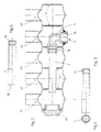
- FIG. 1 and 2 show the foot area of five similar basic elements G1 to G5, which form a hub-like foot area
- Overflow opening U are connected to one another in a liquid-tight and gas-tight manner, for example by directly welding the overflow openings U forming edges.
- a sealing plug VS for closing the left-most basic element at the end G1 is a sealing plug VS in its outer end face used.
- connection piece A To connect the radiator to the radiator flow through a Allowing centrally arranged connection piece A is one of the basic elements G, in the exemplary embodiments the basic element G4, with a Provide bushing 1 as a component provided with a blind hole is executed and has a lateral opening 1a a. This continues with an internally threaded portion 1b is provided in an opening of the Basic element G4 welded.
- the connector A formed by this sleeve 1, through which the radiator is connected to the heating flow is via a dip tube 2 with connected to the foot area of the end element G1, see that the heat-emitting medium the radiator starting with the basic element G1 flows through, although the connection A for the heating flow in middle area of the radiator is arranged,
- the dip tube 2 penetrates the overflow openings U between the Basic elements G1 and G4 lying basic elements G2 and G3 such that the overflow openings U for the transfer of the heat-emitting medium remain.
- the dip tube 2 passed through a sealing washer 3, the the jacket of the dip tube 2 compared to the basic elements G1 and G2 seals and thus closes the overflow opening U.
- This washer 3 is preferably made of permanently elastic material.
- connection-side end of the dip tube 2, which is designed as a straight tube is by means of a liquid-tight connector in the side opening 1a the rifle 1 used.
- connection piece A is inserted in the base area of the basic element G4, which is designed as a pipe bend 5.
- One, in an opening in the hub-like Bottom area of the base element G4 is the end of the pipe bend 5 again with an internal thread section 5b for connecting the heating flow Mistake; the other end of the pipe bend 5 carries in the embodiment also an internal thread 5a.
- the front end of a dip tube 2 is used, which in the Side view and in the front view in Figs. 3 and 4 redrawn is.
- the dip tube 2 executed with a hexagonal cross section and at the front End provided with a threaded portion 2a, which is in the internal thread 5a of the pipe bend 5 can be screwed in under Interpose a seal 4 forming the connector, which at 2 is designed as an O-ring.
- the threaded connection serves to secure the formed by the seal 4 Plug connection.
- Screwing in the at the front end of the dip tube 2 trained threaded portion 2a in the internal thread 5a of the pipe bend 5 is carried out with the aid of a tool, for example a socket wrench with external hexagon or hexagon socket that with the outer surface or the inner surface of the hexagonal cross section of the dip tube 2 cooperates, as can be seen in particular in FIG. 4.
- Fig. 5 shows a further training possibility of a dip tube 2, the is also provided with a threaded portion 2a, but a circular one Has cross section. At the rear end of this dip tube 2 are Key surfaces 2b formed so that this dip tube 2 with the help a suitable tool easily inserted into the connection piece A. and there secured by turning in the end position of the plug connection can be.
- a dip tube 2 with the corresponding Length can either be taken from stock or from a larger pipe Length can be separated.
Landscapes
- Engineering & Computer Science (AREA)
- General Engineering & Computer Science (AREA)
- Thermal Sciences (AREA)
- Mechanical Engineering (AREA)
- Physics & Mathematics (AREA)
- Chemical & Material Sciences (AREA)
- Combustion & Propulsion (AREA)
- Surgical Instruments (AREA)
- Cooling, Air Intake And Gas Exhaust, And Fuel Tank Arrangements In Propulsion Units (AREA)
- Branch Pipes, Bends, And The Like (AREA)
- Resistance Heating (AREA)
- Steam Or Hot-Water Central Heating Systems (AREA)
- Nozzles (AREA)
Description
- Fig. 1
- ein erstes Ausführungsbeispiel anhand eines Längsschnittes durch den Fußbereich mehrerer Grundelemente,
- Fig. 2
- ein der Darstellung in Fig. 1 entsprechendes zweites Ausführungsbeispiel,
- Fig. 3
- eine Seitenansicht des beim Ausführungsbeispiel nach Fig. 2 verwendeten Tauchrohres,
- Fig. 4
- eine Stirnansicht des Tauchrohres nach Fig. 3 und
- Fig. 5
- ein weiteres Ausführungsbeispiel eines mit einem Gewindeabschnitt versehenen Tauchrohres.
- A
- Anschlußstutzen
- G
- Grundelement
- U
- Überströmöffnung
- VS
- Verschlußstopfen
- 1
- Büchse
- 1a
- seitliche Öffnung
- 1b
- Innengewindeabschnitt
- 2
- Tauchrohr
- 2a
- Gewindeabschnitt
- 2b
- Schlüsselfläche
- 3
- Dichtungsscheibe
- 4
- Dichtung
- 4a
- seitliche Öffnung
- 5
- Rohrbogen
- 5a
- Innengewinde
- 5b
- Innengewindeabschnitt
Claims (14)
- Heizkörper, insbesondere Rohrradiator, aus mehreren gleichartigen, seitlich nebeneinander angeordneten und an ihrem nabenartigen Kopf- und Fußbereich unter Ausbildung einer Überströmöffnung (U) flüssigkeitsund gasdicht miteinander verbundenen Grundelementen (G), von denen jeweils eines der Grundelemente (G4) im Fußbereich mit einem Anschlußstutzen (A) für einerseits den Vorlauf und andererseits den Rücklauf versehen ist und mindestens das mit dem Stutzen für den Vorlauf versehene Grundelement (G4) zwischen anderen Grundelementen (G) angeordnet ist, wobei dieser Anschlußstutzen (A) mit dem Fußbereich des jeweils endseitig angeordneten Grundelements (G1) über ein Tauchrohr (2) verbunden ist, das die Überströmöffnungen (U) der dazwischenliegenden Grundelemente (G) durchragt und lediglich gegenüber der Überströmöffnung (U) zwischen dem endseitigen und dem diesem benachbarten Grundelement (G) abgedichtet ist,
dadurch gekennzeichnet, daß das Tauchrohr (2) als gerades Rohr ausgebildet und mit einem Ende mittels einer flüssigkeitsdichten Steckverbindung in eine seitliche Öffnung des in den nabenartigen Fußbereich des jeweiligen Grundelements (G4) hineinragenden Anschlußstutzens (A) eingesetzt ist. - Heizkörper nach Anspruch 1, dadurch gekennzeichnet, daß in den Anschlußstutzen (A) eine das Ende des Tauchrohres (2) gegenüber dem Inneren des Anschlußstutzens (A) abdichtende Dichtung (4) eingesetzt ist.
- Heizkörper nach Anspruch 2, dadurch gekennzeichnet, daß die Dichtung (4) aus dauerelastischem Material hergestellt ist.
- Heizkörper nach mindestens einem der Ansprüche 1 bis 3, dadurch gekennzeichnet, daß der Anschlußstutzen (A) als mit einer seitlichen Bohrung (1a) versehene Büchse (1) ausgebildet ist, die in eine Öffnung im nabenartigen Fußbereich des Grundelements (G4) eingesetzt ist.
- Heizkörper nach Anspruch 4, dadurch gekennzeichnet, daß die Büchse (1) in die Öffnung des Grundelements (G4) eingeschweißt ist.
- Heizkörper nach einem der Ansprüche 4 oder 5, dadurch gekennzeichnet, daß die Büchse (1) als ein mit einer Sacklochbohrung versehenes Bauteil ausgeführt ist.
- Heizkörper nach mindestens einem der Ansprüche 4 bis 6, dadurch gekennzeichnet, daß die Büchse (1) mit einem Innengewindeabschnitt (1b) versehen ist.
- Heizkörper nach mindestens einem der Ansprüche 2 bis 7, dadurch gekennzeichnet, daß die Dichtung (4) als Dichtungsbüchse ausgebildet ist.
- Heizkörper nach mindestens einem der Ansprüche 1 bis 3, dadurch gekennzeichnet, daß der Anschlußstutzen (A) als Rohrbogen (5) ausgebildet ist, dessen eines, vorzugsweise mit einem Innengewindeabschnitt (5b) versehenes Ende in eine Öffnung im nabenartigen Fußbereich des Grundelements (G4) eingesetzt und dessen anderes Ende mit der Steckverbindung für das Tauchrohr (2) versehen ist.
- Heizkörper nach mindestens einem der Ansprüche 1 bis 9, dadurch gekennzeichnet, daß das Tauchrohr (2) mit einem mehreckigen Querschnitt ausgeführt ist.
- Heizkörper nach mindestens einem der Ansprüche 1 bis 10, dadurch gekennzeichnet, daß das Tauchrohr (2) am vorderen Ende mit einem die Steckverbindung sichernden Gewindeabschnitt (2a) versehen ist, der in ein entsprechendes Innengewinde (5a) des Anschlußstutzens (A) eingreift.
- Heizkörper nach Anspruch 11, dadurch gekennzeichnet, daß das Tauchrohr (2) am hinteren Ende mit Schlüsselflächen (2b) für ein Werkzeug versehen ist.
- Heizkörper nach mindestens einem der Ansprüche 1 bis 12, dadurch gekennzeichnet, daß das Tauchrohr (2) im Bereich der Überströmöffnung (U) zwischen dem endseitigen und dem diesem benachbarten Grundelement (G1,G2) durch eine Dichtungsscheibe (3) hindurchgeführt ist, die den Mantel des Tauchrohres (2) gegenüber den Grundelementen (G1,G2) abdichtet und deren Überströmöffnung (U) verschließt.
- Heizkörper nach Anspruch 13, dadurch gekennzeichnet, daß die Dichtungsscheibe (3) aus dauerelastischem Material hergestellt ist.
Applications Claiming Priority (2)
| Application Number | Priority Date | Filing Date | Title |
|---|---|---|---|
| DE29610869U DE29610869U1 (de) | 1996-06-21 | 1996-06-21 | Heizkörper |
| DE29610869U | 1996-06-21 |
Publications (3)
| Publication Number | Publication Date |
|---|---|
| EP0814308A2 EP0814308A2 (de) | 1997-12-29 |
| EP0814308A3 EP0814308A3 (de) | 1998-12-16 |
| EP0814308B1 true EP0814308B1 (de) | 2002-11-20 |
Family
ID=8025477
Family Applications (1)
| Application Number | Title | Priority Date | Filing Date |
|---|---|---|---|
| EP97108573A Expired - Lifetime EP0814308B1 (de) | 1996-06-21 | 1997-05-28 | Heizkörper |
Country Status (3)
| Country | Link |
|---|---|
| EP (1) | EP0814308B1 (de) |
| AT (1) | ATE228229T1 (de) |
| DE (2) | DE29610869U1 (de) |
Cited By (2)
| Publication number | Priority date | Publication date | Assignee | Title |
|---|---|---|---|---|
| DE202008006845U1 (de) | 2008-05-16 | 2008-07-24 | Kermi Gmbh | Heizkörper |
| DE202008007511U1 (de) | 2008-06-03 | 2008-08-14 | Kermi Gmbh | Heizkörper |
Families Citing this family (4)
| Publication number | Priority date | Publication date | Assignee | Title |
|---|---|---|---|---|
| DE19707935C1 (de) | 1997-02-27 | 1998-12-17 | Delta Radiatoren Gmbh | Anschluß für einen Röhrenradiator |
| DE102004029705A1 (de) * | 2004-06-21 | 2006-01-12 | Kermi Gmbh | Heizkörper |
| DE202011052071U1 (de) | 2011-11-23 | 2011-12-30 | Zehnder Verkaufs- Und Verwaltungs Ag | Mehrsäuler-Gliederradiator |
| WO2015136501A1 (en) * | 2014-03-14 | 2015-09-17 | Fondital S.P.A. | Connection device for connecting a heating radiator to a plumbing system |
Family Cites Families (5)
| Publication number | Priority date | Publication date | Assignee | Title |
|---|---|---|---|---|
| DE7641128U1 (de) * | Wella Ag, 6100 Darmstadt | |||
| DE6925171U (de) * | 1969-06-25 | 1971-10-07 | Schlichting Gmbh | Anschlussstopfen fuer den heizmittelaustritt von heizkoerpern. |
| DE2949249A1 (de) * | 1979-12-07 | 1981-06-11 | Benteler-Werke Ag Werk Neuhaus, 4790 Paderborn | Tauchrohr-kombination fuer die wasserverteilung in heizkoerpern |
| DE4308336C2 (de) * | 1993-03-16 | 1996-10-31 | Hkf Heizkoerperfertigung Meini | Mehrsäuliger Wärmekörper |
| DE29502860U1 (de) * | 1995-02-21 | 1995-04-06 | HKF Heizkörperfertigung Meiningen GmbH, 98617 Meiningen | Röhrenradiator |
-
1996
- 1996-06-21 DE DE29610869U patent/DE29610869U1/de not_active Expired - Lifetime
-
1997
- 1997-05-28 AT AT97108573T patent/ATE228229T1/de not_active IP Right Cessation
- 1997-05-28 EP EP97108573A patent/EP0814308B1/de not_active Expired - Lifetime
- 1997-05-28 DE DE59708748T patent/DE59708748D1/de not_active Expired - Lifetime
Cited By (2)
| Publication number | Priority date | Publication date | Assignee | Title |
|---|---|---|---|---|
| DE202008006845U1 (de) | 2008-05-16 | 2008-07-24 | Kermi Gmbh | Heizkörper |
| DE202008007511U1 (de) | 2008-06-03 | 2008-08-14 | Kermi Gmbh | Heizkörper |
Also Published As
| Publication number | Publication date |
|---|---|
| EP0814308A3 (de) | 1998-12-16 |
| DE59708748D1 (de) | 2003-01-02 |
| ATE228229T1 (de) | 2002-12-15 |
| DE29610869U1 (de) | 1996-08-29 |
| EP0814308A2 (de) | 1997-12-29 |
Similar Documents
| Publication | Publication Date | Title |
|---|---|---|
| DE2230191C3 (de) | Rohranschlußverbindung | |
| DE3602499A1 (de) | Kupplungsnippel | |
| DE69907781T2 (de) | Pressfitting für Kunststoffrohre | |
| EP0555650B1 (de) | Adaptierbare Anschlussvorrichtung für Rohre | |
| DE69201143T2 (de) | Rohrschlangenwärmetauscher. | |
| DE3133756A1 (de) | Doppelrohrkuehler | |
| DE19510349C2 (de) | Verbindungselement | |
| EP0814308A2 (de) | Heizkörper | |
| EP0735338B1 (de) | Heizkörper | |
| DE8817020U1 (de) | Lösbare Schnell-Steckverbindung | |
| DE2829216C2 (de) | Heizmittelverteiler | |
| DE2527132A1 (de) | Anschlussvorrichtung fuer einen heizkoerper | |
| DE4325738C2 (de) | Ventilanordnung für die Armatur eines Kompaktheizkörpers | |
| DE3641348A1 (de) | Fluessigkeitsfilter, insbesondere fuer kraftstoffe | |
| DE4011111C1 (en) | Panel radiator connection - has feed and return connections joined to connection piece linking two radiator panels and screwed in place | |
| DE19707935C1 (de) | Anschluß für einen Röhrenradiator | |
| DE10106510B4 (de) | Aluminium-Wärmeübertrager | |
| EP0902228A1 (de) | Rohrschnellkupplung | |
| DE29515269U1 (de) | Verbindungssystem für außen und innen mit Kunststoff beschichtete Sanitärrohre | |
| EP0635687B1 (de) | Zwischen Einrohr- und Zweirohrsystem umstellbares Heizkörperanschlussstück | |
| DE1913968C (de) | Aus Blechformlingen hergestellte Anschlußstutzen für einen Zylinderhahn | |
| DE8710344U1 (de) | Wärmetauscher | |
| DE3616267A1 (de) | Absperr- und belueftungsvorrichtung, insbesondere rohrtrenner fuer trinkwasserleitungen | |
| CH679882A5 (de) | ||
| DE8814730U1 (de) | Übergangsstück |
Legal Events
| Date | Code | Title | Description |
|---|---|---|---|
| PUAI | Public reference made under article 153(3) epc to a published international application that has entered the european phase |
Free format text: ORIGINAL CODE: 0009012 |
|
| AK | Designated contracting states |
Kind code of ref document: A2 Designated state(s): AT BE CH DE FR IT LI LU NL |
|
| PUAL | Search report despatched |
Free format text: ORIGINAL CODE: 0009013 |
|
| AK | Designated contracting states |
Kind code of ref document: A3 Designated state(s): AT BE CH DE FR IT LI LU NL |
|
| 17P | Request for examination filed |
Effective date: 19990607 |
|
| 17Q | First examination report despatched |
Effective date: 20010921 |
|
| GRAG | Despatch of communication of intention to grant |
Free format text: ORIGINAL CODE: EPIDOS AGRA |
|
| GRAG | Despatch of communication of intention to grant |
Free format text: ORIGINAL CODE: EPIDOS AGRA |
|
| GRAH | Despatch of communication of intention to grant a patent |
Free format text: ORIGINAL CODE: EPIDOS IGRA |
|
| GRAH | Despatch of communication of intention to grant a patent |
Free format text: ORIGINAL CODE: EPIDOS IGRA |
|
| GRAA | (expected) grant |
Free format text: ORIGINAL CODE: 0009210 |
|
| AK | Designated contracting states |
Kind code of ref document: B1 Designated state(s): AT BE CH DE FR IT LI LU NL |
|
| REF | Corresponds to: |
Ref document number: 228229 Country of ref document: AT Date of ref document: 20021215 Kind code of ref document: T |
|
| REG | Reference to a national code |
Ref country code: CH Ref legal event code: NV Representative=s name: E. BLUM & CO. PATENTANWAELTE Ref country code: CH Ref legal event code: EP |
|
| REF | Corresponds to: |
Ref document number: 59708748 Country of ref document: DE Date of ref document: 20030102 |
|
| ET | Fr: translation filed | ||
| PLBE | No opposition filed within time limit |
Free format text: ORIGINAL CODE: 0009261 |
|
| STAA | Information on the status of an ep patent application or granted ep patent |
Free format text: STATUS: NO OPPOSITION FILED WITHIN TIME LIMIT |
|
| 26N | No opposition filed |
Effective date: 20030821 |
|
| REG | Reference to a national code |
Ref country code: CH Ref legal event code: PFA Owner name: ZEHNDER VERKAUFS- UND VERWALTUNGS AG Free format text: ZEHNDER VERKAUFS- UND VERWALTUNGS AG#MOORTALSTRASSE 1#5722 GRAENICHEN (CH) -TRANSFER TO- ZEHNDER VERKAUFS- UND VERWALTUNGS AG#MOORTALSTRASSE 1#5722 GRAENICHEN (CH) |
|
| PGFP | Annual fee paid to national office [announced via postgrant information from national office to epo] |
Ref country code: LU Payment date: 20100518 Year of fee payment: 14 Ref country code: FR Payment date: 20100611 Year of fee payment: 14 |
|
| PGFP | Annual fee paid to national office [announced via postgrant information from national office to epo] |
Ref country code: NL Payment date: 20100514 Year of fee payment: 14 Ref country code: IT Payment date: 20100520 Year of fee payment: 14 Ref country code: AT Payment date: 20100513 Year of fee payment: 14 |
|
| PGFP | Annual fee paid to national office [announced via postgrant information from national office to epo] |
Ref country code: CH Payment date: 20100525 Year of fee payment: 14 Ref country code: BE Payment date: 20100517 Year of fee payment: 14 |
|
| BERE | Be: lapsed |
Owner name: *ZEHNDER VERKAUFS- UND VERWALTUNGS A.G. Effective date: 20110531 |
|
| REG | Reference to a national code |
Ref country code: NL Ref legal event code: V1 Effective date: 20111201 |
|
| REG | Reference to a national code |
Ref country code: CH Ref legal event code: PL |
|
| PG25 | Lapsed in a contracting state [announced via postgrant information from national office to epo] |
Ref country code: NL Free format text: LAPSE BECAUSE OF NON-PAYMENT OF DUE FEES Effective date: 20111201 Ref country code: CH Free format text: LAPSE BECAUSE OF NON-PAYMENT OF DUE FEES Effective date: 20110531 Ref country code: LI Free format text: LAPSE BECAUSE OF NON-PAYMENT OF DUE FEES Effective date: 20110531 |
|
| REG | Reference to a national code |
Ref country code: AT Ref legal event code: MM01 Ref document number: 228229 Country of ref document: AT Kind code of ref document: T Effective date: 20110528 |
|
| REG | Reference to a national code |
Ref country code: FR Ref legal event code: ST Effective date: 20120131 |
|
| PG25 | Lapsed in a contracting state [announced via postgrant information from national office to epo] |
Ref country code: AT Free format text: LAPSE BECAUSE OF NON-PAYMENT OF DUE FEES Effective date: 20110528 Ref country code: IT Free format text: LAPSE BECAUSE OF NON-PAYMENT OF DUE FEES Effective date: 20110528 |
|
| PG25 | Lapsed in a contracting state [announced via postgrant information from national office to epo] |
Ref country code: BE Free format text: LAPSE BECAUSE OF NON-PAYMENT OF DUE FEES Effective date: 20110531 |
|
| PG25 | Lapsed in a contracting state [announced via postgrant information from national office to epo] |
Ref country code: FR Free format text: LAPSE BECAUSE OF NON-PAYMENT OF DUE FEES Effective date: 20110531 |
|
| PG25 | Lapsed in a contracting state [announced via postgrant information from national office to epo] |
Ref country code: LU Free format text: LAPSE BECAUSE OF NON-PAYMENT OF DUE FEES Effective date: 20110528 |
|
| PGFP | Annual fee paid to national office [announced via postgrant information from national office to epo] |
Ref country code: DE Payment date: 20160524 Year of fee payment: 20 |
|
| REG | Reference to a national code |
Ref country code: DE Ref legal event code: R071 Ref document number: 59708748 Country of ref document: DE |